Herunterladen Inhalt Inhalt Diese Seite drucken
bürkert 8691 Schnellstart

bürkert 8691 Schnellstart

Steuerkopf
Vorschau ausblenden Andere Handbücher für 8691:
Inhaltsverzeichnis

Werbung

Verfügbare Sprachen

Verfügbare Sprachen

Type 8691
Control Head
Steuerkopf
Tête de commande
Quickstart
English
Deutsch
Français

Werbung

Inhaltsverzeichnis
loading

Inhaltszusammenfassung für bürkert 8691

  • Seite 1 Type 8691 Control Head Steuerkopf Tête de commande Quickstart English Deutsch Français...
  • Seite 2 We reserve the right to make technical changes without notice. Technische Änderungen vorbehalten. Sous réserve de modifications techniques. © 2007 - 2012 Bürkert Werke GmbH Quickstart 1207/03_EU-ML_00806079 / Original DE...
  • Seite 3: Inhaltsverzeichnis

    Type 8691 Contents 1. Quickstart .....................4 7. installation ....................12 1.1. Definition of term “device” .............. 4 7.1. Safety instructions .................12 1.2. Symbols ....................4 7.2. Installation of the control head on process valves of series 21xx ..................12 2. authorized use ..................5 7.3.
  • Seite 4: Quickstart

    A detailed description of the device can be found in the operating Warns of a possible danger! instructions for control head Type 8691. • Failure to observe this warning may result in a medium or minor The operating instructions can be found on the enclosed CD injury.
  • Seite 5: Authorized Use

    • Observe applicable accident prevention and safety regulations careful use and maintenance are essential for reliable and fault- for electrical equipment! less operation. • Use the control head Type 8691 only as intended. 2.1. restrictions If exporting the system/device, observe any existing restrictions. english...
  • Seite 6 Type 8691 Basic safety instructions The control head Type 8691 was developed with due consider- General hazardous situations. ation given to the accepted safety rules and is state-of-the-art. To prevent injury, ensure: Nevertheless, dangerous situations may occur. • Installation and repair work may be carried out by authorized Failure to observe this operating manual and its operating instructions technicians only and with the appropriate tools.
  • Seite 7: General Information

    Fig. 1: Structure 4.2. Warranty The warranty is only valid if the control head Type 8691 is used as The control head Type 8691 can control single or double-acting process valves and has been optimized for the integrated modular fitting intended in accordance with the specified application conditions.
  • Seite 8: Control Head For Integrated Installation On The 21Xx Series

    LED. A special model enables the control head Type 8691 to be attached Option: Communication possible via AS-Interface or DeviceNet. to process valves belonging to the 20xx series.
  • Seite 9: Technical Data

    See data sheet 6.1. conformity Body material exterior: PPS, PC, VA In accordance with the Declaration of conformity, the control head Type 8691 is compliant with the EC Directives. Sealing material exterior: EPDM interior: 6.2. Standards Stroke range of valve spindle: 2 –...
  • Seite 10: Pneumatic Data

    Type 8691 Technical data 6.6. pneumatic data 6.7. electrical data Control medium: neutral gases, air 6.7.1. e lectrical data without bus control 24 V Dc Quality classes in accordance with DIN ISO 8573-1 Dust content Class 5: max. particle size 40 µm, Connections: Cable gland M16 x 1.5, wrench size 22 max.
  • Seite 11 Type 8691 Technical data 6.7.2. e lectrical data with aS-interface bus 6.7.3. e lectrical data with Devicenet bus control control Connections: Circular plug-in connector Connections: Circular plug-in connector (M12 x 1, 5-pole) (M12 x 1, 4-pole) Supply voltage: 11 V – 25 V Supply voltage: 29.5 V – 31.6 V DC (according to specification) Max.
  • Seite 12: Installation

    Type 8691 Installation inSTallaTion 7.2. installation of the control head on process valves of series 21xx Only for control head without pre-assembled process valve. Procedure: When the control head is being installed, the collets of the 7.1. Safety instructions pilot air ports must not be fitted to the actuator. Danger! →...
  • Seite 13: Installation Of The Control Head On Process Valves Of Series 20Xx

    Type 8691 Installation → Push the control head, without turning it, onto the actuator until 7.3. installation of the control head on no gap is visible on the form seal. process valves of series 20xx note! Procedure: too high torque when screwing in the fastening screw does Guide rail not ensure protection class ip65 / ip67! • The fastening screws may be tightened to a maximum torque of 0.5 Nm only.
  • Seite 14 (maximum torque: 0.5 Nm). “In rest position” means that the pilot valves of the control Pilot air outlet 2 head Type 8691 are isolated or not actuated. Pilot air outlet 2 If the ambient air is humid, a hose can be connected...
  • Seite 15: Fluid Installation

    Type 8691 Fluid installation fluiD inSTallaTion control function a (cfa) Process valve closed in rest position (by spring force) 8.1. Safety instructions Pilot air outlet Danger! risk of injury from high pressure! Upper pilot air port • Before dismounting pneumatic lines and valves, turn off the pressure and vent the lines. Lower pilot air port...
  • Seite 16: Installing The Process Valve

    Type 8691 Fluid installation 8.2. installing the process valve Important information for the problem-free functioning of the device: Thread type and dimensions can be found in the corresponding data sheet. • The installation must not cause back pressure to build up. → Connect the valve according to the operating instructions for the •...
  • Seite 17: Electrical Installation

    Type 8691 Electrical installation elecTrical inSTallaTion 9.2. electrical installation 24 V Dc 9.2.1. e lectrical installation with cable gland 9.1. Safety instructions procedure: Danger! → The screw terminals can be accessed by unscrewing the body risk of electric shock! casing (stainless steel). → • Before reaching into the system, switch off the power supply Push the cables through the cable gland.
  • Seite 18: Configuration

    Type 8691 Electrical installation 9.2.2. e lectrical installation 24 V Dc with circular plug-in connector → Body casing Connect the control head according to the table. The teach function can now be used to automatically determine and read in the end positions of the valve (description of the teach function Seal see chapter “10.
  • Seite 19: Display Elements 24 V Dc

    Type 8691 Electrical installation 9.4. programming data aS-interface 9.3. Display elements 24 V Dc as-interface as-interface Top LEDs 31 slaves 62 slaves I/O configuration B hex (1 input, 2 outputs) Status LED (yellow) ID code F hex A hex Extended ID code 1 F hex 7 hex LED pilot valve (yellow)
  • Seite 20: Electrical Installation As-Interface

    Type 8691 Electrical installation 9.5. electrical installation aS-interface Bus connection without external / with external supply voltage 9.5.1. c onnection with circular plug-in designation configuration connector m12 x 1, 4-pole, male Bus + AS-Interface bus line + NC or GND not used or external supply voltage – Connector views (optional) (optional) The views show the image from the front looking at the pins, the Bus –...
  • Seite 21: C Onnection With Multi-Pole Cable And Ribbon Cable Terminal

    M12 plug-in connector be started via the bus protocol. branch circuit Fig. 16: Control head 8691 with multi-pole cable and ribbon cable terminal handling the ribbon cable terminal The multi-pole cable features a ribbon cable terminal - with M12 plug-in connector branch circuit - for AS-Interface cable harness. The ribbon cable terminal contacts the AS-Interface cable harness by means of penetration technology which allows installation by “clipping in”...
  • Seite 22: Display Elements As-Interface

    Type 8691 Electrical installation 9.6. D isplay elements aS-interface Bus led Bus led (green) (red) Status LED yellow POWER OFF Top LEDs No data traffic (expired Watch Dog at slave Pilot valve LED yellow address does not equal 0) Bus LED green Bus LED red...
  • Seite 23: Electrical Installation Devicenet

    Type 8691 Electrical installation 9.7. e lectrical installation Devicenet 9.7.2. configuring the control head Setting the Dip switches 9.7.1. B us connection (circular connector m12 x 1, 5-pole, male) The control head features a 5-pole micro-style circular connector. The following configuration conforms to the DeviceNet specification. DIP switches → for bus address Connect the control head according to the table.
  • Seite 24 Type 8691 Electrical installation → settings of the devicenet address Check that the seal is correctly positioned in the body casing. → MAC ID – Medium Access Control Identifier: Close the device (assembly tool: 674077 [DIP 1=off=0 / DIP 1=on=1 / note! MAC ID=DIP 1*2 +DIP 2*2 +...+DIP 6*2...
  • Seite 25: Display Elements Devicenet

    Type 8691 Electrical installation The teach function can now be used to automatically determine color and read in the end positions of the valve (description of the teach Status LED flashing yellow Teach function is running function see chapter “10. Teach function”).
  • Seite 26 Type 8691 Electrical installation status of the bus status led status of the device status led device status explanation troubleshooting device status explanation Device is not supplied No supply Device is not supplied with voltage Connect other devices, with voltage if the device is the only Device has still not Green Device is working...
  • Seite 27: Teach Function

    Type 8691 Teach function 10. Teach funcTion note! The teach function can be used to automatically determine and read damage or malfunction due to penetration of dirt and humidity! in the end positions of the valve. • To observe protection class IP65 / IP67, screw the transparent cap in all the way.
  • Seite 28: Safety Positions

    Type 8691 Safety positions 11. SafeTy poSiTionS 13. packaGinG, TranSporT, SToraGe safety positions after failure of the auxiliary power note! actuator system designation electrical pneumatic transport damages! Inadequately protected equipment may be damaged during transport. single-acting • During transportation protect the device against wet and dirt in down down Control shock-resistant packaging.
  • Seite 29 Typ 8691 Inhaltsverzeichnis 1. der Quickstart ..................30 7. montaGe ......................38 1.1. Begriffsdefinition Gerät ..............30 7.1. Sicherheitshinweise ...............38 1.2. Darstellungsmittel ................30 7.2. Montage Steuerkopf an Prozessventile der Reihe 21xx ..38 7.3. Montage Steuerkopf an Prozessventile der Reihe 20xx ..39 2. BestimmunGsGemässe VerWendunG ........31 8. fluidische installation ..............
  • Seite 30: Der Quickstart

    Der Quickstart erläutert beispielhaft die Montage und Inbetriebnahme des Geräts. Warnt vor einer möglichen Gefährdung! Die ausführliche Beschreibung des Geräts finden Sie in der Bedie- • Nichtbeachtung kann mittelschwere oder leichte Verletzungen nungsanleitung für den Steuerkopf Typ 8691. zur Folge haben. hinWeis! Die Bedienungsanleitung finden Sie auf der beigelegten CD Warnt vor sachschäden! oder im Internet unter: www.buerkert.de...
  • Seite 31: Bestimmungsgemässe Verwendung

    Typ 8691 Bestimmungsgemäße Verwendung BeSTimmunGSGemäSSe GrunDleGenDe VerWenDunG SicherheiTShinWeiSe Diese Sicherheitshinweise berücksichtigen keine Bei nicht bestimmungsgemäßem einsatz des steuerkopfs typ 8691 können Gefahren für personen, anlagen in der • Zufälligkeiten und Ereignisse, die bei Montage, Betrieb und umgebung und die umwelt entstehen. Wartung der Geräte auftreten können. • Das Gerät ist für den Anbau an pneumatische Antriebe von Pro- • ortsbezogenen Sicherheitsbestimmungen, für deren Einhaltung, zessventilen zur Steuerung von Medien konzipiert.
  • Seite 32 Typ 8691 Grundlegende Sicherheitshinweise Der Steuerkopf Typ 8691 wurde unter Einbeziehung der allgemeine Gefahrensituationen. anerkannten sicherheitstechnischen Regeln entwickelt und Zum Schutz vor Verletzungen ist zu beachten: entspricht dem Stand der Technik. Trotzdem können Gefahren • Dass die Anlage nicht unbeabsichtigt betätigt werden kann.
  • Seite 33: Allgemeine Hinweise

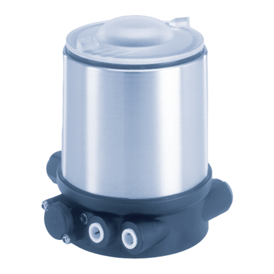
    Bild 1: Aufbau 4.2. Gewährleistung Der Steuerkopf Typ 8691 kann einfach- oder doppeltwirkende Pro- Voraussetzung für die Gewährleistung ist der bestimmungsgemäße zessventile ansteuern und ist für den integrierten, modularen Anbau Gebrauch des Steuerkopfs Typ 8691 unter Beachtung der spezifi- an Prozessventile der Reihe 21xx optimiert.
  • Seite 34: Steuerkopf Für Den Integrierten Anbau An 21Xx

    Typ 8691 Systembeschreibung 5.3. Variante zur ansteuerung von Neben der elektrischen Stellungsrückmeldung wird der Gerätestatus am Steuerkopf selbst optisch durch farbige Hochleistungs-LEDs (Top prozessventilen der reihe 20xx LEDs) dargestellt. Mit einer speziellen Variante kann der Steuerkopf an Prozessventile Option: Kommunikation über AS-Interface oder DeviceNet möglich. der Reihe 20xx angebaut werden.
  • Seite 35: Technische Daten

    Technische Daten TechniSche DaTen 6.4. mechanische Daten Abmessungen: siehe Datenblatt 6.1. konformität Gehäusematerial außen: PPS, PC, VA Der Steuerkopf Typ 8691 ist konform zu den EG-Richtlinien entspre- chend der EG-Konformitätserklärung. Dichtungsmaterial außen: EPDM innen: NBR 6.2. normen Hubbereich Ventilspindel: 2 ... 28 mm Die Konformität zu den EG-Richtlinien wird durch folgende Normen...
  • Seite 36: Pneumatische Daten

    Typ 8691 Technische Daten 6.6. pneumatische Daten 6.7. elektrische Daten Steuermedium: neutrale Gase, Luft 6.7.1. e lektrische Daten ohne Qualitätsklassen nach DIN ISO 8573-1 Busansteuerung 24 V Dc Staubgehalt Klasse 5: max. Teilchengröße 40 µm, Anschlüsse: Kabelverschraubung M16 x 1,5 SW22 (Klemmbereich 5 - 10 mm) max. Teilchendichte 10 mg/m mit Schraubklemmen für...
  • Seite 37 Typ 8691 Technische Daten 6.7.2. e lektrische Daten mit Busansteuerung 6.7.3. e lektrische Daten aS-interface mit Busansteuerung Devicenet Anschlüsse: Rundsteckverbinder Anschlüsse: Rundsteckverbinder (M12 x 1, 5-polig) (M12 x 1, 4-polig) Betriebsspannung 11 V ... 25 V Betriebsspannung: 29,5 V ... 31,6 V DC Max. Stromaufnahme < 80 mA (gemäß...
  • Seite 38: Montage

    Typ 8691 Montage monTaGe 7.2. montage Steuerkopf an prozessventile der reihe 21xx Nur für Steuerkopf ohne vormontiertes Prozessventil. Vorgehensweise: Bei der Montage des Steuerkopfs dürfen die Collets der Steuerluftanschlüsse am Antrieb nicht montiert sein. 7.1. Sicherheitshinweise → Den Puckhalter und den Steuerkopf so ausrichten, dass gefahr! 1.
  • Seite 39: Montage Steuerkopf An Prozessventile Der Reihe 20Xx

    Typ 8691 Montage → 7.3. montage Steuerkopf an Den Steuerkopf ohne Drehbewegung soweit auf den Antrieb schieben, dass an der Formdichtung kein Spalt mehr sichtbar ist. prozessventile der reihe 20xx hinWeis! Vorgehensweise: durch ein zu hohes drehmoment beim einschrauben der Führungsschiene Befestigungsschraube kann die schutzart ip65 / ip67 nicht sichergestellt werden! • Die Befestigungsschraube darf nur mit einem maximalen Dreh- moment von 0,5 Nm angezogen werden.
  • Seite 40 Den Steuerkopf mit den beiden seitlichen Befestigungsschrauben „In Ruhestellung“ bedeutet, dass das Steuerventil des Steu- auf dem Antrieb befestigen. Dabei die Befestigungsschrauben nur erkopfs Typ 8691 stromlos bzw. nicht betätigt ist. leicht anziehen (maximales Drehmoment: 0,5 Nm). Bei feuchter Umgebungsluft kann bei Steuerfunktion A bzw.
  • Seite 41: Fluidische Installation

    Typ 8691 Fluidische Installation fluiDiSche inSTallaTion steuerfunktion a (sfa) Prozessventil in Ruhestellung geschlossen (durch Federkraft) 8.1. Sicherheitshinweise Steuerluftausgang gefahr! Verletzungsgefahr durch hohen druck in der anlage! oder Steuerluftanschluss oben • Vor dem Lösen von Leitungen und Ventilen den Druck abschal- ten und Leitungen entlüften. Steuerluftanschluss unten Verletzungsgefahr durch elektrische spannung! • Vor Eingriffen in das Gerät oder in die Anlage die Spannung...
  • Seite 42: Installation Des Prozessventils

    Typ 8691 Fluidische Installation 8.2. installation des prozessventils Wichtiger Hinweis zur einwandfreien Funktion des Geräts: Gewindeart und Abmessungen sind dem entsprechenden Datenblatt • Durch die Installation darf sich kein Rückdruck aufbauen. zu entnehmen. • Für den Anschluss einen Schlauch mit ausreichendem → Das Prozessventil entsprechend der Bedienungsanleitung des Querschnitt wählen.
  • Seite 43: Elektrische Installation

    Typ 8691 Elektrische Installation elekTriSche inSTallaTion 9.2. e lektrische installation 24 V Dc 9.2.1. e lektrische installation mit 9.1. Sicherheitshinweise kabelverschraubung gefahr! Vorgehensweise: → Verletzungsgefahr durch elektrische spannung! Durch Herausdrehen des Gehäusemantels (Edelstahl) werden die Schraubklemmen zugänglich. • Vor Eingriffen in das System die Spannung abschalten und vor → Wiedereinschalten sichern! Die Kabel durch die Kabelverschraubung schieben.
  • Seite 44 Typ 8691 Elektrische Installation 9.2.2. e lektrische installation mit rundsteckverbinder → Gehäusemantel Den Steuerkopf entsprechend der Tabelle anschließen. Mit Hilfe der Teachfunktion können nun die Endstellungen des Ventils automatisch ermittelt und eingelesen werden (Beschreibung Dichtung der Teachfunktion siehe Kapitel „10. Teachfunktion“). Gehäusemantel Bild 11: Position Dichtung Gehäusemantel →...
  • Seite 45: Anzeigeelemente 24 V Dc

    Typ 8691 Elektrische Installation 9.4. p rogrammierdaten aS-interface 9.3. anzeigeelemente 24 V Dc as-interface as-interface Top LEDs 31 slaves 62 slaves E/A-Konfiguration B hex (1 Ausgang, 2 Eingänge) Status LED (gelb) ID-Code F hex A hex Erweiterter ID-Code 1 F hex 7 hex LED Steuerventil (gelb) Erweiterter ID-Code 2...
  • Seite 46: Elektrische Installation As-Interface

    Typ 8691 Elektrische Installation 9.5. elektrische installation aS-interface Busanschluss ohne externe / mit externer Versorgungsspannung 9.5.1. e lektrischer anschluss mit Bezeichnung Belegung rundsteckverbinder m12 x 1, 4-polig Bus + Busleitung AS-Interface + nicht belegt oder externe Versor- NC oder GND steckeransichten gungsspannung – (optional) (optional) Die Ansichten zeigen jeweils das Bild von vorn auf die Stifte, die Löt- anschlüsse liegen dahinter.
  • Seite 47: Anschluss Mit Multipolkabel Und Flachkabelklemme

    M12 Steckverbinder Bei der Bus-Variante AS-Interface kann die Teachfunktion Abgang auch über das Busprotokoll gestartet werden. Bild 16: Steuerkopf 8691 mit Multipolkabel und Flachkabelklemme handhabung der flachkabelklemme Am Multipolkabel befindet sich eine, mit M12 Steckverbinder Abgang versehene, Flachkabelklemme für AS-Interface-Formkabel. Die Flach- kabelklemme realisiert die Kontaktierung des AS-Interface-Formkabels in Form einer Durchdringungstechnik, die eine Installation durch „Ein-...
  • Seite 48: Anzeigeelemente As-Interface

    Typ 8691 Elektrische Installation 9.6. a nzeigeelemente aS-interface Bus led Bus led anzeige (grün) (rot) Status LED gelb POWER OFF Top LEDs kein Datenverkehr (abgelaufener Watch-Dog Steuerventil LED gelb bei Slaveadresse ungleich 0) Bus LED grün Bus LED rot blinkt Slaveadresse gleich 0 Jumper: Überlast der Sensorversorgung oder externer...
  • Seite 49: Elektrische Installation Devicenet

    Typ 8691 Elektrische Installation 9.7. e lektrische installation Devicenet 9.7.2. konfigurieren des Steuerkopfs einstellung Dip-Schalter 9.7.1. B us-anschluss (m12-rundstecker, 5-polig, male) Der Steuerkopf besitzt einen 5-poligen Micro-Style-Rundstecker. Die nachfolgende Belegung entspricht der DeviceNet-Spezifikation. DIP-Schalter → Den Steuerkopf entsprechend der Tabelle anschließen. für Busadresse und Baudrate signal Schirm V –...
  • Seite 50 Typ 8691 Elektrische Installation → einstellungen der devicenet-adresse Die korrekte Position der Dichtung im Gehäusemantel prüfen. → MAC ID – Medium Access Control Identifier: Das Gehäuse schließen (Schraubwerkzeug: 674077 [DIP 1=off=0 / DIP 1=on=1 / hinWeis! MAC ID=DIP 1*2 +DIP 2*2 +...+DIP 6*2 Beschädigung oder funktionsausfall durch eindringen von...
  • Seite 51: Anzeigeelemente Devicenet

    Typ 8691 Elektrische Installation Mit Hilfe der Teachfunktion können nun die Endstellungen des farbe anzeige Ventils automatisch ermittelt und eingelesen werden (Beschreibung Status LED blinkt gelb Teachfunktion läuft der Teachfunktion siehe Kapitel „10. Teachfunktion“). Puckplatine nicht flackert gelb vorhanden Bei der Bus-Variante DeviceNet kann die Teachfunktion leuchten grün...
  • Seite 52 Typ 8691 Elektrische Installation Zustand der Bus LeD Geräte- erläuterung problembeseitigung zustand Geräte- erläuterung problembeseitigung zustand ein weiteres Gerät mit Gerät ist nicht mit der gleichen MAC ID weitere Geräte Spannung versorgt Adresse befindet sich Baudrate checken anschließen, falls das Kritischer im Kreis Gerät der einzige Netz-...
  • Seite 53: Teachfunktion

    Typ 8691 Teachfunktion 10. TeachfunkTion hinWeis! Mit Hilfe der Teachfunktion können die Endstellungen des Ventils Beschädigung oder funktionsausfall durch eindringen von automatisch ermittelt und eingelesen werden. Verschmutzung und feuchtigkeit! • Zur Einhaltung der Schutzart IP65 / IP67 die Klarsichthaube bis Bei den Bus-Varianten AS-Interface und DeviceNet kann die auf Anschlag einschrauben.
  • Seite 54: Sicherheitsstellungen

    Typ 8691 Sicherheitsstellungen 11. SicherheiTSSTellunGen 13. TranSporT, laGerunG, VerpackunG sicherheitsstellungen nach ausfall der hilfsenergie hinWeis! antriebssart Bezeichnung elektrisch pneumatisch transportschäden! Unzureichend geschützte Geräte können durch den Transport einfach- beschädigt werden. wirkend down down • Gerät vor Nässe und Schmutz geschützt in einer stoßfesten Steuer- Verpackung transportieren.
  • Seite 55 Type 8691 Sommaire 1. Quickstart ....................56 7. montaGe ......................64 1.1. Définition du terme « appareil » ...........56 7.1. Consignes de sécurité ..............64 1.2. Symboles..................56 7.2. Montage de la tête de commande sur les vannes process des séries 21xx ........64 2. utilisation conforme...............
  • Seite 56: Quickstart

    1.1. Définition du terme « appareil » Le terme « appareil » utilisé dans ces instructions désigne toujours la renvoie à des informations dans ces instructions de service tête de commande type 8691. ou dans d’autres documentations. → identifie une opération que vous devez effectuer.
  • Seite 57: Utilisation Conforme

    • Veillez à ce que l’utilisation de la tête de commande type 8691 soit toujours conforme. 2.1. restrictions Lors de l’exportation du système / de l’appareil, veuillez respecter les restrictions éventuelles existantes.
  • Seite 58 Type 8691 Consignes de sécurité fondamentales La tête de commande type 8691 a été développée dans situations dangereuses d’ordre général. le respect des règles reconnues en matière de sécurité et Pour prévenir les blessures, respectez ce qui suit : correspond à l’état actuel de la technique. Néanmoins, des •...
  • Seite 59: Indications Générales

    La condition pour bénéficier de la garantie légale est l’utilisation à simple ou à double effet et est optimisée pour le montage modulaire conforme de la tête de commande type 8691 dans le respect des intégré sur des vannes de processus de la série 21xx (Element) . La conditions d’utilisation spécifiées.
  • Seite 60: Tête De Commande Pour Le Montage Intégré Sur La Série 21Xx

    Type 8691 Description du Système 5.3. Variante de commande des vannes En plus de l’indicateur de position électrique, l’état de l’appareil est indiqué sur la tête de commande par des Top LED de couleur. process de la série 20xx Option : communication possible par interface AS ou DeviceNet. Une variante spéciale permet de monter la tête de commande sur les vannes process de la série 20xx.
  • Seite 61: Caractéristiques Techniques

    Cotes voir fiche technique 6.1. conformité Matériau du corps extérieur: PPS, PC, VA La tête de commande type 8691 est conforme aux directives CE sur la base de la déclaration de conformité CE. Matériau d’étanchéité extérieur: EPDM intérieur: 6.2. normes Course de la tige de vanne: 2 ...
  • Seite 62: Caractéristiques Pneumatiques

    Type 8691 Caractéristiques techniques 6.6. caractéristiques pneumatiques 6.7. caractéristiques électriques Fluide de commande gaz neutres, air 6.7.1. c aractéristiques électriques sans commande bus 24 V Dc Classes de qualité selon DIN ISO 8573-1 Raccordements : Presse-étoupes M16 x 1,5, SW22 Teneur en poussières Classe 5 Taille maximale des particules (bornes 5 ...
  • Seite 63: C Aractéristiques Électriques Avec Commande Bus Devicenet

    Type 8691 Caractéristiques techniques 6.7.2. c aractéristiques électriques avec 6.7.3. c aractéristiques électriques avec commande bus interface aS commande bus Devicenet Raccordements : Connecteur rond Raccordements : Connecteur rond (M12 x 1, 5 pôles) (M12 x 1, 4 pôles) Alimentation en tension : 11 V à 25 V Tension d’alimentation : 29,5 V ...
  • Seite 64: Montage

    Type 8691 Montage monTaGe 7.2. montage de la tête de commande sur les vannes process des séries Uniquement pour tête de commande sans vanne process 21xx prémontée. Lors du montage de la tête de commande, les collets des rac- 7.1. consignes de sécurité cords d’air de pilotage ne doivent pas être montés sur l’actionneur.
  • Seite 65: Montage De La Tête De Commande Sur Les Vannes Process De La Série 20Xx

    Type 8691 Montage → 7.3. montage de la tête de commande Glisser la tête de commande sur l’actionneur sans la faire tourner jusqu’à ce que le joint profilé ne présente plus d’interstice. sur les vannes process de la série 20xx remarque ! procédure à suivre : le type de protection ip65 / ip67 ne peut être garanti si le Rail de guidage couple de serrage de la vis de fixation est trop élevé. • Les vis de fixation doivent être serrées uniquement avec un couple de serrage maximal de 0,5 Nm.
  • Seite 66 IP65 / IP67. Sortie d’air de pilotage 2 « En position de repos » signifie que les vannes pilote de la tête de commande type 8691 ne sont pas alimentées en courant Sortie d’air de pilotage 2 ou ne sont pas activées.
  • Seite 67: Installation Fluidique

    Type 8691 Installation fluidique inSTallaTion fluiDiQue fonction a (cfa) Vanne process fermée en position de repos (par ressort) 8.1. consignes de sécurité Sortie d’air de pilotage Danger ! danger dû à la haute pression. Raccord d’air de pilotage supérieure • Avant de desserrer les conduites et les vannes, coupez la pres- sion et assurez l'échappement de l'air des conduites.
  • Seite 68: Installation De La Vanne Process

    Type 8691 Installation fluidique 8.2. installation de la vanne process Remarque importante concernant le parfait fonctionnement de l’appareil : Le type de filet et les dimensions peuvent être consultés dans la fiche technique correspondante. • L’installation ne doit pas générer de contre-pression. → Raccorder la vanne conformément aux instructions de service la •...
  • Seite 69: Installation Électrique

    Type 8691 Installation électrique inSTallaTion élecTriQue 9.2. i nstallation électrique 24 V Dc 9.2.1. i nstallation électrique avec 9.1. consignes de sécurité presse-étoupe Danger ! procédure à suivre : → risque de blessures par la tension électrique. Les bornes à vis sont accessibles en dévissant l’enveloppe du corps (acier inoxydable). • Avant d'intervenir dans le système, coupez la tension et empêchez →...
  • Seite 70 Type 8691 Installation électrique 9.2.2. i nstallation électrique 24 V Dc avec connecteur rond → Enveloppe du corps Raccorder la tête de commande conformément au tableau. La fonction didactique permet maintenant de déterminer et de lire automatiquement les positions finales de la vanne (description de la Joint fonction didactique voir chapitre «...
  • Seite 71: Eléments D'affichage 24 V Dc

    Type 8691 Installation électrique 9.3. eléments d’affichage 24 V Dc remarque ! dommage ou panne suite à la pénétration d’encrassement et LED Top d’humidité. • Visser le capot transparent jusqu’en butée afin de respecter le Status LED (jaune) type de protection IP65 / IP67. LED vanne pilote (jaune) 9.4. D onnées de programmation interface aS Fig. 13 : Eléments d’affichage 24 V DC...
  • Seite 72: Installation Électrique Interface As

    Type 8691 Installation électrique 9.5. installation électrique interface aS Raccordement bus sans / avec tension d’alimentation externe 9.5.1. r accordement avec connecteur rond Broche désignation affectation m12 x 1, 4 pôles, mâle Bus + Câble bus interface AS + NC ou GND non affecté ou tension d’alimen- Vues du connecteur : (en option) tation externe –...
  • Seite 73: Raccordement Avec Câble Multipolaire Et Borne À Câble Plat

    Avec la variante bus interface AS, la fonction didactique peut enfichable sortie être démarrée également avec le protocole bus. Fig. 16 : Tête de commande 8691 avec câble multipolaire et borne à câble plat manipulation de la borne à câble plat Le câble multipolaire dispose d’une borne à câble plat pourvue d’une sortie connecteur M12 pour le câble de forme de l’interface AS.
  • Seite 74: Eléments D'affichage Interface As

    Type 8691 Installation électrique 9.6. e léments d’affichage interface aS Bus Bus led led Status LED jaune (verte) (rouge) LED Top éteinte éteinte POWER OFF LED vanne pilote (jaune) Aucune exploitation des données (chien de garde éteinte allumée Bus LED verte terminé avec adresse esclave différente de 0) Bus LED rouge allumée éteinte...
  • Seite 75: Elektrische Installation Devicenet

    Type 8691 Installation électrique 9.7. e lektrische installation Devicenet 9.7.2. configuration de la tête de commande réglage des interrupteurs Dip 9.7.1. r accordement bus (connecteur rond m12 x 1, 5 pôles, mâle) La tête de commande possède un connecteur rond 5 pôles de style micro. L’affectation suivante correspond à la spécification DeviceNet. Interrupteurs DIP → Raccorder la tête de commande conformément au tableau.
  • Seite 76 Type 8691 Installation électrique paramètres pour l’adresse devicenet Une modification des réglages par actionnement des inter- MAC ID – Medium Access Control Identifier: rupteurs DIP ne devient effective qu’après redémarrage de l’appareil. [DIP 1=off=0 / DIP 1=on=1 / MAC ID=DIP 1*2 +DIP 2*2 +...+DIP 6*2 →...
  • Seite 77: Eléments D'affichage Devicenet

    Type 8691 Installation électrique La fonction didactique permet maintenant de déterminer et de lire couleur automatiquement les positions finales de la vanne (description de la Status LED Fonction didactique en fonction didactique voir chapitre « 10. Fonction Didactique »). clignote en jaune...
  • Seite 78 Type 8691 Installation électrique etat de la LeD d’état bus etat de explication elimination du problème l’appareil etat de explication elimination du problème l’appareil Un autre appareil L’appareil n’est pas avec la même alimenté en tension adresse MAC ID se Contrôler la vitesse de Raccorder d’autres appa- trouve dans le circuit transmission L’appareil n’a pas...
  • Seite 79: Fonction Didactique

    Type 8691 Fonction Didactique remarque ! 10. foncTion DiDacTiQue La fonction didactique permet de déterminer et de lire automati- dommage ou panne suite à la pénétration d’encrassement et d’humidité. quement les positions finales de la vanne. • Visser le capot transparent jusqu’en butée afin de respecter le Avec la variante bus interface AS et DeviceNet, la fonction type de protection IP65 / IP67.
  • Seite 80: Positions De Sécurité

    Type 8691 Positions de sécurité 11. poSiTionS De SécuriTé 13. emBallaGe, TranSporT, STockaGe réglages de sécurité après une panne de l’énergie remarque ! type désignation auxiliaire d’actionneur dommages dus au transport. électrique pneumatique Les appareils insuffisamment protégés peuvent être endommagés pendant le transport. simple effet • Transportez l'appareil à l'abri de l'humidité et des impuretés et...
  • Seite 82 www.burkert.com...

Inhaltsverzeichnis