bürkert 8695 Bedienungsanleitung
Vorschau ausblenden
Andere Handbücher für 8695:
- Bedienungsanleitung (192 Seiten) ,
- Schnellstartanleitung (26 Seiten) ,
- Zusatzanleitung (16 Seiten)
Inhaltsverzeichnis
Werbung
Verfügbare Sprachen
Verfügbare Sprachen
Quicklinks
Werbung
Kapitel
Inhaltsverzeichnis

Verwandte Anleitungen für bürkert 8695


Inhaltszusammenfassung für bürkert 8695
- Seite 1 Type 8695 Control Head Steuerkopf Tête de commande Quickstart...
- Seite 2 We reserve the right to make technical changes without notice. Technische Änderungen vorbehalten. Sous réserve de modifications techniques. © 2007 - 2011 Bürkert Werke GmbH Quickstart 1103/01_EU-ML_00805384 / Original DE...
-
Seite 3: Inhaltsverzeichnis
Type 8695 TableofContents 7. installation ....................11 1. Quickstart .....................4 7.1. Safety Instructions .................11 1.1. Symbols ....................4 7.2. Installation of the Control Head 2. authorized use ..................5 on Process Valves of Series 21xx ..........11 2.1. Restrictions ..................5 7.3. Installation of the Control Head on Process Valves of Series 20xx ..........12... -
Seite 4: Quickstart
A detailed description of the device can be found in the operating Warns of a possible danger! instructions for control head Type 8695. • Failure to observe this warning may result in a medium or minor The operating instructions can be found on the enclosed CD injury. -
Seite 5: Authorized Use
• Correct transportation, correct storage and installation and careful use and maintenance are essential for reliable and fault- less operation. • Use the control head Type 8695 only as intended. english... -
Seite 6: Basic Safety Instructions
• Before dismounting pneumatic lines and valves, turn off the pressure and vent the lines. The control head Type 8695 was developed with due con- sideration given to the accepted safety rules and is state-of- risk of electric shock! the-art. -
Seite 7: General Information
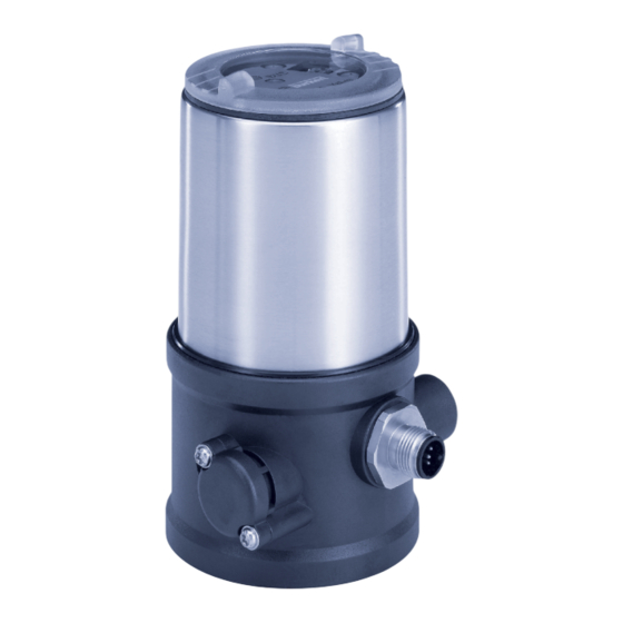
Process valve www.burkert.com Valve body 4.2. Warranty The warranty is only valid if the control head Type 8695 is used as Fig. 1: Structure 1 intended in accordance with the specified application conditions. Depending on the conditions of use, different process valves from 4.3. information on the internet... -
Seite 8: Technical Data
Type 8695 TechnicalData The control head Type 8695 has been optimized for the integrated Technical daTa modular fitting of series 21xx process valves (Element) with a 50 mm 6.1. conformity actuator. Various expansion stages are possible thanks to the modular design. In accordance with the Declaration of conformity, the control head Type 8695 is compliant with the EC Directives. -
Seite 9: Mechanical Data
Supply voltage / Control Control function - value according to definition for Type - Pilot valve pressure drop from 7 to 6 bar absolute) 8695 24 V DC Nominal pressure Connections: 21xx single act Pilot 0,6 (Element): Plug-in hose connector ∅ 6mm / 1/4“... -
Seite 10: Electrical Data
Type 8695 TechnicalData 6.7. electrical data 6.7.2. e lectrical data with as interface bus control 6.7.1. e lectrical data without bus control 24 V dc Connections: Circular plug-in connector (M12 x 1, 4-pole) Connections: Circular plug-in connector Profile: S-B.A.E. (A/B slave, max. 62 (M12 x 1, 8-pole) slaves/master) Pilot valve: Electrical supply voltage: 29.5 V –... -
Seite 11: Installation
Type 8695 Installation insTallaTion 7.2. installation of the control head on Process Valves of series 21xx Only for control head without pre-assembled process valve. Procedure: When the control head is being installed, the collets of the 7.1. safety instructions pilot air ports must not be fitted to the actuator. Danger! →... -
Seite 12: Installation Of The Control Head On Process Valves Of Series 20Xx
Type 8695 Installation → 7.3. installation of the control head on Push the control head, without turning it, onto the actuator until no gap is visible on the form seal. Process Valves of series 20xx Procedure: note! Guide rail too high torque when screwing in the fastening screw does Supports not ensure protection class ip65 / ip67! • The fastening screws may be tightened to a maximum torque of 0.5 Nm only. - Seite 13 In doing so, tighten the fastening screws hand- tight only (maximum torque: 0.5 Nm). “In rest position” means that the pilot valves of the control head Type 8695 are isolated or not actuated. Fastening screws (2x) If the ambient air is humid, a hose can be connected...
-
Seite 14: Fluid Installation
Type 8695 FluidInstallation fluid insTallaTion control function (cf) pneumatic connection type 8695 with actuator 8.1. safety instructions pilot air pilot air port actuator Danger! outlet type 8695 risk of injury from high pressure! • Before dismounting pneumatic lines and valves, turn off the pressure and vent the lines. lower pilot air port of the Process valve risk of electric shock! actuator closed in rest •... -
Seite 15: Installing The Process Valve
Type 8695 FluidInstallation 8.2. installing the Process Valve Important information for the problem-free functioning of the device: Thread type and dimensions can be found in the corresponding data sheet. • The installation must not cause back pressure to build up. → Connect the valve according to the operating instructions for the •... -
Seite 16: Electrical Installation
Type 8695 ElectricalInstallation elecTrical insTallaTion 9.2. electrical installation 24 V dc with circular Plug-in connector 9.1. safety instructions → Connect the control head according to the table. Danger! The Teach function can now be used to automatically determine and read in the end positions of the valve (description of the Teach risk of electric shock! function see chapter “10. -
Seite 17: Display Elements 24 V Dc
Type 8695 ElectricalInstallation 9.3. display elements 24 V dc 9.4. e lectrical installation as interface End position LED green 9.4.1. c onnection with circular Plug-in connector M12 x 1, 4-pole, male Jumper for assignment of Pin 3: Pin 4: end position LEDs Bus – Status LED yellow End position LED yellow Pin 1: Pin 2:... -
Seite 18: C Onnection With Multi-Pole Cable And Ribbon Cable Terminal
For the bus variant AS Interface, the Teach function can also M12 plug-in connector be started via the bus protocol. branch circuit Fig. 12: Control head 8695 with multi-pole cable and ribbon cable terminal 9.5. Programming data handling the ribbon cable terminal I/O configuration B hex... -
Seite 19: Display Elements As Interface
Type 8695 ElectricalInstallation 9.6. display elements as interface Bus led Bus led (green) (red) End position LED green POWER OFF No data traffic (expired Watch Dog at Bus LED red slave address does not equal 0) Bus LED green flashing Slave address equals 0 Jumper for... -
Seite 20: Teach Function
Type 8695 Teachfunction 10. Teach funcTion note! The teach function can be used to automatically determine and read damage or malfunction due to penetration of dirt and humidity! in the end positions of the valve. • To observe protection class IP65 / IP67, screw the transparent cap in all the way. -
Seite 21: Safety Positions
Type 8695 SafetyPositions 11. safeTy PosiTions 12. accessories safety positions after designation order no. failure of the auxiliary actuator designation power system Connection cable M12 x 1, 8-pole 919061 electrical pneumatic Assembly tool 674078 single-acting Tab. 9: Accessories Control down down function A down single-acting Control function B... -
Seite 22: Packaging, Transport, Storage
Type 8695 Packaging,Transport,Storage 13. PackaGinG, TransPorT, sToraGe note! transport damages! Inadequately protected equipment may be damaged during transport. • During transportation protect the device against wet and dirt in shock-resistant packaging. • Avoid exceeding or dropping below the permitted storage temperature. incorrect storage may damage the device. • Store the device in a dry and dust-free location! •... - Seite 23 Typ 8695 Inhaltsverzeichnis 8. fluidische installation ..............34 1. der Quickstart ..................24 8.1. Sicherheitshinweise ...............34 1.1. Darstellungsmittel ................24 8.2. Installation des Prozessventils .............35 2. BestimmunGsGemässe VerWendunG ........25 8.3. Pneumatischer Anschluss des Steuerkopfs ......35 2.1. Beschränkungen ................25 9. elektrische installation .............. 36 2.2.
-
Seite 24: Der Quickstart
Geräts. • Nichtbeachtung kann mittelschwere oder leichte Verletzungen Die ausführliche Beschreibung des Geräts finden Sie in der Bedie- zur Folge haben. nungsanleitung für den Typ 8695. hinWeis! Die Bedienungsanleitung finden Sie auf der beigelegten CD oder im Internet unter: Warnt vor sachschäden! -
Seite 25: Bestimmungsgemässe Verwendung
Typ 8695 BestimmungsgemäßeVerwendung BesTiMMunGsGeMässe 2.1. Beschränkungen VerWendunG Beachten Sie bei der Ausfuhr des Systems/Geräts gegebenenfalls Bei nicht bestimmungsgemäßem einsatz des steuerkopfs bestehende Beschränkungen. typ 8695 können Gefahren für personen, anlagen in der umgebung und die umwelt entstehen. 2.2. Vorhersehbarer fehlgebrauch • Das Gerät ist für den Anbau an pneumatische Antriebe von Pro- • Speisen Sie in den Steuerluftanschluss keine aggressiven oder zessventilen zur Steuerung von Medien konzipiert. -
Seite 26: Grundlegende Sicherheitshinweise
• Vor dem Lösen von Leitungen oder Ventilen den Druck abschal- allgemeinen Regeln der Technik eingehalten werden. ten und Leitungen entlüften. Gefahr durch elektrische spannung! Der Steuerkopf Typ 8695 wurde unter Einbeziehung der • Vor Eingriffen in das Gerät oder die Anlage, Spannung abschal- anerkannten sicherheitstechnischen Regeln entwickelt ten und vor Wiedereinschalten sichern! und entspricht dem Stand der Technik. -
Seite 27: Allgemeine Hinweise
Typ 8695 AllgemeineHinweise allGeMeine hinWeise sysTeMBeschreiBunG 4.1. kontaktadresse 5.1. aufbau und funktion Deutschland Der Steuerkopf Typ 8695 kann einfach- oder doppeltwirkende Pro- zessventile ansteuern. Bürkert Fluid Control Systems Sales Center Christian-Bürkert-Str. 13-17 D-74653 Ingelfingen Steuerkopf Tel. + 49 (0) 7940 - 10 91 111 Fax + 49 (0) 7940 - 10 91 448 E-mail: info@de.buerkert.com... -
Seite 28: Technische Daten
Typ 8695 TechnischeDaten Der Steuerkopf Typ 8695 ist für den integrierten, modularen Anbau an Technische daTen Prozessventile der Reihe 21xx (Element) mit 50er Antrieb optimiert. Der 6.1. konformität modulare Aufbau ermöglicht verschiedene Ausbaustufen. Der Steuerkopf Typ 8695 ist konform zu den EG-Richtlinien entspre- Für den Anbau an die Reihe 20xx (Classic) gibt es eine spezielle... -
Seite 29: Mechanische Daten
Betriebsspannung / Druckabfall von 7 auf 6 bar absolut) Ansteuerung Steuerfunktion - Steuerventil Anschlüsse Schlauchsteckverbinder ∅ 6mm / 1/4“ 21xx (Element): 8695 24 V DC Nenndruck single act Pilot 0,6 Muffenanschluss G 1/8 Pmax 7bar Max. Umgebungs- Tamb 0°C - +55°C... -
Seite 30: Elektrische Daten
Typ 8695 TechnischeDaten 6.7. elektrische daten 6.7.2. e lektrische daten mit Busansteuerung as-interface 6.7.1. e lektrische daten ohne Anschlüsse: Rundsteckverbinder Busansteuerung 24 V dc (M12 x 1, 4-polig) Anschlüsse: Rundsteckverbinder Profil: S-B.A.E (A/B slave, max. 62 (M12 x 1, 8-polig) slaves/master) Steuerventil: Betriebsspannung: 29,5 V ... 31,6 V DC Betriebsspannung 24 V DC ±... -
Seite 31: Montage
Typ 8695 Montage MonTaGe 7.2. Montage steuerkopf an Prozessventile der reihe 21xx Nur für Steuerkopf ohne vormontiertes Prozessventil. Vorgehensweise: Bei der Montage des Steuerkopfs dürfen die Collets der 7.1. sicherheitshinweise Steuerluftanschlüsse am Antrieb nicht montiert sein. gefahr! → Den Puckhalter und den Steuerkopf so ausrichten, dass Verletzungsgefahr durch hohen druck in der anlage! 1. -
Seite 32: Montage Steuerkopf An Prozessventile Der Reihe 20Xx
Typ 8695 Montage → 7.3. Montage steuerkopf an Den Steuerkopf ohne Drehbewegung soweit auf den Antrieb schieben, dass an der Formdichtung kein Spalt mehr sichtbar ist. Prozessventile der reihe 20xx hinWeis! Vorgehensweise: durch ein zu hohes drehmoment beim einschrauben der Führungsschiene Befestigungsschraube kann die schutzart ip65 / ip67 nicht Stutzen sichergestellt werden! • Die Befestigungsschraube darf nur mit einem maximalen Dreh- moment von 0,5 Nm angezogen werden. - Seite 33 „In Ruhestellung“ bedeutet, dass das Steuerventil des Steu- auf dem Antrieb befestigen. Dabei die Befestigungsschrauben nur leicht anziehen (maximales Drehmoment: 0,5 Nm). erkopfs Typ 8695 stromlos bzw. nicht betätigt ist. Bei feuchter Umgebungsluft kann bei Steuerfunktion A bzw. bei Steuerfunktion B eine Schlauchverbindung zwischen...
-
Seite 34: Fluidische Installation
Typ 8695 FluidischeInstallation fluidische insTallaTion steuerfunktion pneumatische Verbindung typ 8695 mit antrieb 8.1. sicherheitshinweise steuerluft- steuerluftanschluss gefahr! ausgang antrieb typ 8695 Verletzungsgefahr durch hohen druck in der anlage! • Vor dem Lösen von Leitungen und Ventilen den Druck abschal- unterer Steuerluftanschluss Prozessventil ten und Leitungen entlüften. des Antriebs in Ruhestellung Verletzungsgefahr durch elektrische spannung! sollte mit oberem Steuer- geschlossen •... -
Seite 35: Installation Des Prozessventils
Typ 8695 FluidischeInstallation 8.2. installation des Prozessventils Wichtiger Hinweis zur einwandfreien Funktion des Geräts: Gewindeart und Abmessungen sind dem entsprechenden Datenblatt • Durch die Installation darf sich kein Rückdruck aufbauen. zu entnehmen. • Für den Anschluss einen Schlauch mit ausreichendem → Das Prozessventil entsprechend der Bedienungsanleitung des Querschnitt wählen. -
Seite 36: Elektrische Installation
Typ 8695 ElektrischeInstallation elekTrische insTallaTion 9.2. elektrische installation 24 V dc mit rundsteckverbinder 9.1. sicherheitshinweise → Den Steuerkopf entsprechend der Tabelle anschließen. gefahr! Mit Hilfe der Teachfunktion können nun die Endlagen des Ventils automatisch ermittelt und eingelesen werden (Beschreibung der Verletzungsgefahr durch elektrische spannung! Teachfunktion siehe Kapitel „10. Teachfunktion“). • Vor Eingriffen in das System die Spannung abschalten und vor Wiedereinschalten sichern! •... -
Seite 37: Anzeigeelemente 24 V Dc
Typ 8695 ElektrischeInstallation 9.3. anzeigeelemente 24 V dc 9.4. elektrische installation as-interface Endlage LED grün 9.4.1. e lektrischer anschluss mit rundsteckverbinder M12 x 1, 4-polig Jumper für Zuordnung der Pin 3: Pin 4: Endlagen LEDs Bus – Status LED gelb Endlage LED gelb Pin 1: Pin 2: Valve LED gelb (Steuerventil) -
Seite 38: A Nschluss Mit Multipolkabel Und Flachkabelklemme
Schrauben M12 Steckverbinder Bei der Bus-Variante AS-Interface kann die Teachfunktion Abgang auch über das Busprotokoll gestartet werden. Bild 12: Steuerkopf 8695 mit Multipolkabel und Flachkabelklemme 9.5. Programmierdaten as-interface handhabung der flachkabelklemme E/A-Konfiguration B hex Am Multipolkabel befindet sich eine, mit M12 Steckverbinder Abgang... -
Seite 39: Anzeigeelemente As-Interface
Typ 8695 ElektrischeInstallation 9.6. anzeigeelemente as-interface Bus led Bus led (grün) (rot) Endlage LED grün POWER OFF Bus LED rot kein Datenverkehr (abgelaufener Watch-Dog bei Slaveadresse ungleich 0) Bus LED grün Jumper für blinkt Slaveadresse gleich 0 Zuordnung Status LED gelb der End- Überlast der Sensorversorgung (Peripherie-... -
Seite 40: Teachfunktion
Typ 8695 Teachfunktion 10. TeachfunkTion hinWeis! Mit Hilfe der Teachfunktion können die Endlagen des Ventils auto- Beschädigung oder funktionsausfall durch eindringen von matisch ermittelt und eingelesen werden. Verschmutzung und feuchtigkeit! • Zur Einhaltung der Schutzart IP65 / IP67 die Klarsichthaube bis Bei der Bus-Variante AS-Interface kann die Teachfunktion auf Anschlag einschrauben. -
Seite 41: Sicherheitsstellungen
Typ 8695 Sicherheitsstellungen 11. sicherheiTssTellunGen 12. zuBehör sicherheitsstellungen Bezeichnung Bestell-nr. nach ausfall der hilfsenergie antriebssart Bezeichnung Anschlusskabel M12 x 1, 8-polig 919061 pneuma- elektrisch tisch Schraubwerkzeug 674078 einfach- Tab. 9: Zubehör wirkend down down Steuer- funktion A down einfach- wirkend Steuer- funktion B... -
Seite 42: Transport, Lagerung, Verpackung
Typ 8695 Transport,Lagerung,Verpackung 13. TransPorT, laGerunG, VerPackunG hinWeis! transportschäden! Unzureichend geschützte Geräte können durch den Transport beschädigt werden. • Gerät vor Nässe und Schmutz geschützt in einer stoßfesten Verpackung transportieren. • Eine Über- bzw. Unterschreitung der zulässigen Lagertempe- ratur vermeiden. • Elektrische Schnittstellen der Spule und die pneumatischen Anschlüsse mit Schutzkappen vor Beschädigungen schützen. - Seite 43 7. montaGe ......................51 1. Quickstart ....................44 7.1. Consignes de sécurité ..............51 1.1. Symboles..................44 7.2. Montage de la tête de commande type 8695 2. utilisation conforme............... 45 sur les vannes process des séries 21xx ........51 2.1. Restrictions ..................45 7.3. Montage de la tête de commande sur les vannes process de la série 20xx ........52...
-
Seite 44: Quickstart
Vous trouverez la description détaillée de l’appareil dans le manuel dangereuse. d’utilisation du type 8695. • Risque de blessures graves, voire la mort en cas de non-respect. Vous trouverez les instructions de service sur le CD fourni ou remarque ! bien sur Internet sous : met en garde contre des dommages matériels. -
Seite 45: Utilisation Conforme
• Les conditions pour l’utilisation sûre et parfaite sont un trans- port, un stockage et une installation dans les règles ainsi qu’une parfaite utilisation et maintenance. • Veillez à ce que l’utilisation de la tête de commande type 8695 soit toujours conforme. français... -
Seite 46: Consignes De Sécurité Fondamentales
• Avant d’intervenir dans l’appareil ou l’installation, coupez la ten- La tête de commande type 8695 a été développée dans sion et empêchez toute remise sous tension par inadvertance. le respect des règles reconnues en matière de sécurité et •... -
Seite 47: Indications Générales
Vanne process www.burkert.com 4.2. Garantie légale Corps de vanne La condition pour bénéficier de la garantie légale est l’utilisation conforme de la tête de commande type 8695 dans le respect des conditions d’utilisation spécifiées. Fig. 1 : Structure 1 4.3. informations sur internet Selon les conditions d’utilisation, il est possible de combiner différentes... -
Seite 48: Caractéristiques Techniques
Type 8695 Caractéristiquestechniques La tête de commande type 8695 est optimisée pour le montage modu- caracTérisTiQues TechniQues laire intégré sur des vannes de processus de la série 21xx (Element) 6.1. conformité avec actionneur 50. La structure modulaire permet différentes étapes de développement. -
Seite 49: Caractéristiques Mécaniques
/min (pour alimentation en air et Vanne pilote échappement) (Q selon la définition de la 8695 24 V DC Pression nominale chute de pression de 7 à 6 bars absolue) single act Pilot 0,6 Pmax 7bar Température... -
Seite 50: Caractéristiques Électriques
Type 8695 Caractéristiquestechniques 6.7. caractéristiques électriques 6.7.2. c aractéristiques électriques avec commande bus interface as 6.7.1. c aractéristiques électriques sans Raccordements : Connecteur rond commande bus 24 V dc (M12 x 1, 4 pôles) Raccordements : Connecteur rond Profil : S-B.A.E. (A/B slave, max. 62 (M12 x 1, 8 pôles) slaves/master) Vanne pilote Tension d’alimentation :... -
Seite 51: Montage
Type 8695 Montage MonTaGe 7.2. Montage de la tête de commande type 8695 sur les vannes process Uniquement pour tête de commande sans vanne process des séries 21xx prémontée. Lors du montage de la tête de commande, les collets des rac- 7.1. consignes de sécurité cords d’air de pilotage ne doivent pas être montés sur l’actionneur. -
Seite 52: Montage De La Tête De Commande Sur Les Vannes Process De La Série 20Xx
Type 8695 Montage → 7.3. Montage de la tête de commande Glisser la tête de commande sur l’actionneur sans la faire tourner jusqu’à ce que le joint profilé ne présente plus d’interstice. sur les vannes process de la série 20xx remarque ! procédure à suivre : le type de protection ip65 / ip67 ne peut être garanti si le Rail de guidage couple de serrage de la vis de fixation est trop élevé. Manchons • Les vis de fixation doivent être serrées uniquement avec un couple de serrage maximal de 0,5 Nm. - Seite 53 (couple de serrage maxi : 0,5 Nm). « En position de repos » signifie que les vannes pilote de la tête de commande type 8695 ne sont pas alimentées en courant Vis de fixation (2x) ou ne sont pas activées.
-
Seite 54: Installation Fluidique
Type 8695 Installationfluidique insTallaTion fluidiQue fonction raccordement pneumatique type 8695 à l’actionneur 8.1. consignes de sécurité sortie raccord d’air de pilotage Danger ! d’air de d’actionneur pilotage danger dû à la haute pression. type 8695 • Avant de desserrer les conduites et les vannes, coupez la pres- Raccord d’air de pilotage sion et assurez l'échappement de l'air des conduites. -
Seite 55: Installation De La Vanne Process
Type 8695 Installationfluidique 8.2. installation de la vanne process Remarque importante concernant le parfait fonctionnement de l’appareil : Le type de filet et les dimensions peuvent être consultés dans la fiche technique correspondante. • L’installation ne doit pas générer de contre-pression. → Raccorder la vanne conformément aux instructions de service la •... -
Seite 56: Installation Électrique
Type 8695 Installationélectrique insTallaTion élecTriQue 9.2. i nstallation électrique 24 V dc avec connecteur rond 9.1. consignes de sécurité → Raccorder la tête de commande conformément au tableau. Danger ! La fonction didactique permet maintenant de déterminer et de lire automatiquement les positions finales de la vanne (description de la risque de blessures par la tension électrique. -
Seite 57: Eléments D'affichage 24 V Dc
Type 8695 Installationélectrique 9.3. eléments d’affichage 24 V dc 9.4. i nstallation électrique interface as Position finale LED verte 9.4.1. r accordement avec connecteur rond M12 x 1, 4 pôles, mâle Cavalier pour l’affectation des LED de position finale Bus – Status LED jaune Position finale LED jaune Valve LED jaune (vanne pilote) Bus + Fig. -
Seite 58: R Accordement Avec Câble Multipolaire Et Borne À Câble Plat
Avec la variante bus interface AS, la fonction didactique peut M12 connecteur être démarrée également avec le protocole bus. enfichable sortie Fig. 12 : Tête de commande 8695 avec câble multipolaire et borne à câble plat 9.5. données de programmation interface as manipulation de la borne à câble plat... -
Seite 59: Eléments D'affichage Interface As
Type 8695 Installationélectrique 9.6. eléments d’affichage interface as Bus led Bus led (verte) (rouge) Position finale LED verte éteinte éteinte POWER OFF Bus LED rouge Aucune exploitation des données (chien de éteinte allumée garde terminé avec adresse esclave diffé- rente de 0) Bus LED verte allumée éteinte... -
Seite 60: Fonction Didactique
Type 8695 FonctionDidactique 10. foncTion didacTiQue remarque ! La fonction didactique permet de déterminer et de lire automati- dommage ou panne suite à la pénétration d’encrassement et quement les positions finales de la vanne. d’humidité. • Visser le capot transparent jusqu’en butée afin de respecter le Avec la variante bus interface AS, la fonction didactique peut type de protection IP65 / IP67. -
Seite 61: Positions De Sécurité
Type 8695 Positionsdesécurité 11. PosiTions de sécuriTé 12. accessoires réglages de sécurité désignation n° de commande après une panne de type l’énergie auxiliaire désignation d’actionneur Câble de raccordement M12 x1, 8 pôles 919061 pneuma- électrique tique Outil de montage 674078 Tab. 9 : Accessoires simple effet down down Fonction A down... -
Seite 62: Emballage, Transport, Stockage
Type 8695 Emballage,transport,Stockage 13. eMBallaGe, TransPorT, sTockaGe remarque ! dommages dus au transport. Les appareils insuffisamment protégés peuvent être endommagés pendant le transport. • Transportez l'appareil à l'abri de l'humidité et des impuretés et dans un emballage résistant aux chocs. • Évitez le dépassement vers le haut ou le bas de la température de stockage admissible. - Seite 64 www.burkert.com...