
Verwandte Anleitungen für Hameg HMS 3000


Inhaltszusammenfassung für Hameg HMS 3000
- Seite 1 1 G H z / 3 G H z S p e c t r u m - A n a l y z e r H M S S e r i e s Handbuch / Manual Deutsch / English...
-
Seite 2: Allgemeine Hinweise Zur Ce-Kennzeichnung
Messkabel zu Einspeisung unerwünschter Signalteile EN 61326-1/A1 Störaussendung / Radiation / Emission: in das Messgerät kommen. Dies führt bei HAMEG Messgeräten nicht zu Tabelle / table / tableau 4; Klasse / Class / Classe B. einer Zerstörung oder Außerbetriebsetzung des Messgerätes. -
Seite 3: Inhaltsverzeichnis
I n h a l t s v e r z e i c h n i s Allgemeine Geräteeinstellungen English Spracheinstellung Allgemeine Einstellung Schnittstellen-Einstellung Drucker-Einstellung Deutsch Referenz-Frequenz Update (Firmware / Hilfe) CE-Konformitätserklärung Upgrade mit Softwareoptionen Spektrum Analysator HMS Serie Anschlüsse an der Gerätevorderseite USB-Anschluss Technische Daten... -
Seite 4: Spektrum Analysator Hms Serie
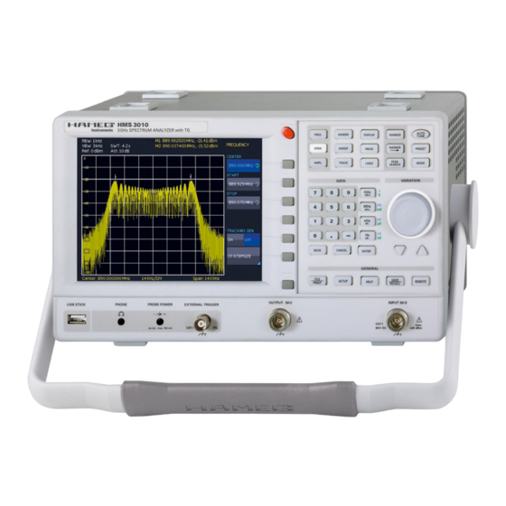
S p e k t r u m A n a l y s a t o r H M S S e r i e 3 G H z S p e k t r u m a n a ly s a t o r H M S 3 0 0 0 / H M S 3 0 1 0 1 GHz Spektrumanalysator HMS1000 ohne TG... -
Seite 5: Technische Daten
HMS3000/3010D/121010 · C&E · Änderungen vorbehalten · © HAMEG Instruments GmbH ® · DQS-zertifiziert nach DIN EN ISO 9001:2008, Reg. Nr.: 071040 QM08 HAMEG Instruments GmbH · Industriestr. 6 · D-63533 Mainhausen · Tel +49 (0) 6182 8000 · Fax +49 (0) 6182 800100 · www.hameg.com · info@hameg.com... -
Seite 6: Installations- Und Sicherheitshinweise
I n s t a l l a t i o n s - u n d S i c h e r h e i t s h i n w e i s e Sicherheit 1 Installations- und Sicherheitshinweise Dieses Gerät ist gemäß... -
Seite 7: Gewährleistung Und Reparatur
Fall per Internet: http://www.hameg.com oder Fax eine RMA-Nummer an. Sollte Ihnen keine geeignete Verpackung zur Verfügung stehen, so können Sie einen leeren Originalkarton über den HAMEG-Service (Tel: +49 (0) 6182 800 500, Fax: +49 (0) 6182 800 501, E-Mail: service@hameg.com) bestellen. Wartung Die Außenseite des Spektrumanalysators sollte regelmäßig mit... -
Seite 8: Bezeichnung Der Bedienelemente
K u r z b e s c h r e i b u n g d e r B e d i e n e l e m e n t e Abschnitt (Data): 2 Bezeichnung der Bedienelemente Dieser Abschnitt beinhaltet die Einstellmöglichkeiten via Tastatur und Einheitstasten. -
Seite 9: Geräterückseite
K u r z b e s c h r e i b u n g d e r B e d i e n e l e m e n t e Geräte-Rückseite SAVE/RECALL (Taste beleuchtet) Laden und Abspeichern von Geräteeinstellungen, Refe- renzkurven, Kurven und Bildschirmfotos Anschluss der Stromversorgung mit Sicherung REMOTE (Taste beleuchtet) -
Seite 10: Schnelleinstieg
Im folgenden Kapitel werden Sie mit den wichtigsten Funktionen ebenfalls als Linien dargestellt (hier noch nicht zu erkennen). und Einstellungen Ihres neuen HAMEG HMS Spektrumanalysa- Um das Generatorsignal bei 100 MHz näher zu untersuchen, tors vertraut gemacht, so dass Sie das Gerät umgehend einsetzen wird im Frequenz-Einstellmenü... -
Seite 11: Auswahl Der Richtigen Filtereinstellungen
S c h n e l l e i n s t i e g bei 200 MHz zu finden sein. Abhängig von der Reinheit des an- Aktivieren Sie nun die manuelle VBW Auswahl mit einem Druck gelegten Signals kann die Oberwelle (mit den derzeit gewählten auf die zugehörige Softkeytaste und wählen aus dem erschei- Einstellungen) entsprechend gut oder schlecht sichtbar sein. -
Seite 12: Einstellung Des Referenzpegels
S c h n e l l e i n s t i e g Schrift des derzeit selektierten Markers ist im oberen Anzeige- Um dies zu verhindern, sind die Eingangsabschwächer (Atte- segment (dort wo die Frequenz- und Pegelwerte des Marker nuator) vom Spektrumanalysator selbstständig geschaltet und abgelesen werden können) hell hervorgehoben. -
Seite 13: Einstellen Von Parametern
E i n s t e l l e n v o n P a r a m e t e r n So geben Sie einen numerischen Wert ein 4 Einstellen von Parametern – Wählen Sie mit Hilfe der grauen Softmenütasten ihren Menüpunkt. -
Seite 14: Gerätefunktionen
Der Spektrumanalysator zeigt am Signalausgang des Tra- cking-Generators kein „echtes“ Sinussignal. Dies war zwar führt, dass die Start- und Stoppfrequenz entsprechend auto- bei vorherigen HAMEG Spektrumanalysatoren der Fall, ist für matisch eingestellt werden. den Betrieb eines Tracking-Generators jedoch nicht zwingend notwendig. -
Seite 15: Einstellung Der Amplitudenparameter (Ampl)
G e r ä t e f u n k t i o n e n Die HMS Serie bietet bei der Spektrumsdarstellung Spans zwi- Verstärkung dahingehend optimiert, dass ein möglichst schen 1 kHz und 1 GHz (HMS1000/1010) bzw. 100 Hz und 3 GHz großer Signal-Rausch-Abstand erzielt wird. -
Seite 16: Einstellung Des Wobbelablaufs (Sweep)
G e r ä t e f u n k t i o n e n Einstellung der Messkurve (TRACE) Durch Druck auf die Taste TRACE gelangt man in das Ein- stellungsmenü. Die Darstellung einer Messkurve kann auf verschiedene Weisen erfolgen (TRACE MODE): –... -
Seite 17: Detektoren
G e r ä t e f u n k t i o n e n MATH die Differenz aus der im Speicher abgelegten Messkurve Frequenzposition des Markers ist durch ein Pfeilsymbol und der aktiven Messkurve angezeigt werden. Zum Ausblenden gekennzeichnet. -
Seite 18: Grenzwertlinien (Limit Lines)
G e r ä t e f u n k t i o n e n – MINIMUM: die Funktion setzt den Marker oder den Delta- z.B. Frequenz, Amplitude oder Auflösungsbandbreite, können Marker auf den minimalsten Messwertausschlag der über die entsprechenden Tasten eingestellt und mit Hilfe des Messkurve;... -
Seite 19: Speichern/Laden Von Geräteeinstellungen
S p e i c h e r n / L a d e n v o n G e r ä t e e i n s t e l l u n g e n Hier können Sie den Speicherort (Interner Speicher, vor- 6 Speichern/Laden von Geräteeinstellungen derer USB- oder hinterer USB-Anschluss) wählen, einen Dateinamen sowie einen Kommentar einfügen und mit dem... -
Seite 20: Kurven
Formaten abgespeichert werden: tation ist das Bildschirmfoto. Die Einstellungen zu Speicherort und Format sind nur möglich, wenn Sie mindestens einen HAMEG Binärformat: In einer Binärdatei kann jeder beliebige USB-Stick angeschlossen haben. Das Einstellen erfolgt in dem Bytewert vorkommen. Die aufgenommenen Kurvendaten wer- Menü, welches sich öffnet, wenn Sie die SAVE/RECALL-Taste... -
Seite 21: Abb. 6.7: Speichern Und Laden Menü
S p e i c h e r n / L a d e n v o n G e r ä t e e i n s t e l l u n g e n B e i s p i e l e i n e s B i l d s c h i r m f o t o s Buchstaben vorgeben. -
Seite 22: Erweiterte Bedienfunktionen
Anzeige-Einstellung Zur Durchführung einer EMV-Messung benötigen Sie eine von Durch Drücken der Taste DISPLAY gelangt man ins Einstell- HAMEG kostenlos zur Verfügung gestellten Software, welche Sie menü des Bildschirms. Hier haben Sie mehrere Einstellungen auf www.hameg.com herunterladen können. Weiterführende zur Auswahl: Informationen zur HAMEG EMV Software entnehmen Sie bitte der softwareseitig integrierten Hilfe-Funktion. -
Seite 23: Allgemeine Geräteeinstellungen
Referenzsignal genutzt. Update (Firmware / Hilfe) Sollte eine aktuellere Firmware für Ihr HMS verfügbar sein, können Sie sich diese unter www.hameg.com herunterladen. Die Firmware ist in eine ZIP-Datei gepackt. Wenn Sie die ZIP- Datei heruntergeladen haben, entpacken Sie diese auf einen USB- Stick (siehe 9.1 USB-Anschluss) in dessen Basisver-... -
Seite 24: Upgrade Mit Softwareoptionen
A l l g e m e i n e G e r ä t e e i n s t e l l u n g e n Klartext gelesen werden. Um die gewünschte Option mit die- sem Schlüssel im Gerät freizuschalten, gibt es zwei Verfahren: das automatisierte Einlesen oder die manuelle Eingabe. -
Seite 25: Anschlüsse An Der Gerätevorderseite
Skriptsprache SCPI (= Standard Commands for Program- mable Instruments). Mittels der mitgelieferten USB/RS-232 Dual-Schnittstelle (optional Ethernet/USB oder IEEE-488 GPIB) haben Sie die Möglichkeit, Ihr HAMEG-Gerät extern über eine Remote-Verbindung (Fernsteuerung) zu steuern. Dabei haben sie auf nahezu alle Funktionen Zugriff, die Ihnen auch im ma- nuellen Betrieb über das Front-Panel zur Verfügung stehen. -
Seite 26: Optionales Zubehör
Sonden schon eingebauten Vorverstärker (Verstärkung ca. 30 dB) erübrigen den Einsatz von externen Zusatzgeräten. Die Sonden werden entweder durch einsetzbare Batterien/ Akkus betrieben (HZ530) oder können direkt aus dem HAMEG Spektrumanalysator mit Spannung versorgt werden (HZ540). Die schlanke Bauform erlaubt guten Zugang zur prüfenden Schaltung auch in beengter Prüfumgebung. -
Seite 27: Anhang
A n h a n g 13 Anhang Center-Frequenz: 22 CISPR: 12, 18 CISPR-Norm: 18 13.1 Abbildungsverzeichnis Abb. 3.1: Abschnitt A des Bedienfeldes Dateimanager: 19, 20, 24 Abb. 3.2: Anzeige mit AUTO TUNE Funktion Delta-Marker: 17, 18 Abb. 3.3: Pegelmessung mit Marker Demodulation: 18, 25 Abb. - Seite 28 A n h a n g Pegelverlauf: 18 Preamplifier: 26 Quasi-Peak: 18 Quasi-Peak-Detektor: 12, 18 Rauschen: 15, 16, 17 Rauschleistungsdichte: 17 Rauschsignalen: 17 Rauschteppich: 10, 11, 18 Rauschverhältnis: 15 Receiver-Modus: 18 Referenz-Level: 15 Referenzfrequenz: 23, 25 Referenzlevel: 15 Referenzpegel: 12, 15, 17 RMS-Detektor: 18 SAMPLE: 17 Sicherungshalter: 7...
- Seite 29 A n h a n g Änderungen vorbehalten...
-
Seite 30: General Information Concerning The Ce Marking
General information concerning the CE marking HAMEG instruments fulfill the regulations of the EMC directive. The conformity test made by HAMEG is based on the actual generic- and product standards. In cases where different limit values are applicable, HAMEG applies the severer standard. For emission the limits for residential, commercial and light industry are applied. -
Seite 31: English
C o n t e n t General instrument settings Deutsch Language settings Basic settings Interface settings English Printer settings Reference frequency General information concerning the CE marking Update (Firmware / Help) Upgrade of software options Spectrum Analyzer: HMS Series Front panel connections Specifications USB connector... - Seite 32 H M S S e r i e s 3 G H z S p e c t r u m A n a l y z e r H M S 3 0 0 0 / H M S 3 0 1 0 1 GHz Spectrum Analyzer HMS1000 without TG R Frequency Range 100 kHz…3 GHz...
- Seite 33 · DQS-certified in accordance with DIN EN ISO 9001:2008, Reg.-No.: 071040 QM08 HAMEG Instruments GmbH · Industriestr. 6 · D-63533 Mainhausen · Tel +49 (0) 6182 8000 · Fax +49 (0) 6182 800100 · www.hameg.com · info@hameg.com Subject to change without notice...
-
Seite 34: Installation And Safety Instructions
I n s t a l l a t i o n a n d s a f e t y i n s t r u c t i o n s Removal/fitting of the handle: The handle can be removed in 1 Installation and safety instructions position F, pulling the side parts outside the housing. -
Seite 35: Warranty And Repair
(http://www.hameg.com) or fax (+49 (0) 6182 800 501). If you do not have an original shipping carton, you may obtain one by calling the HAMEG service dept (+49 (0) 6182 800 500) or by sending an email to service@hameg.com. -
Seite 36: Controls And Display
C o n t r o l s a n d d i s p l a y Area (Data): 2 Controls and display This area includes the possibility of setting parameters via numerical keyboard and unit keys. Front panel (HMS1010 differs in frequency range;... -
Seite 37: Rear Panel
C o n t r o l s a n d d i s p l a y REMOTE (illuminated button) DVI (connector) Toggling between front panel and external operation Connection of external monitors and projectors USB port Area This area includes a series of connectors. REF IN (BNC socket) Reference input USB port... -
Seite 38: Quick Introduction
The following chapters are intended to introduce you to the here). In order to analyze the generator signal further, use the most important functions and settings of your new HAMEG HMS frequency settings menu (key FREQ ) to set the start frequen- spectrum analyzer in order to enable you to immediately use it. -
Seite 39: Fig. 3.4: Measurement Of The Harmonic Of A Sine Wave Signal
Q u i c k i n t r o d u c t i o n Activate the marker by pressing the soft key DISPLAY. The se- Another means of spectrum analysis is the socalled video cond marker will now appear in the center of the display. Select bandwidth (VBW). -
Seite 40: Fig. 3.7: Peak Search Function
Q u i c k i n t r o d u c t i o n the HMS will switch to the receiver mode and measures the level of the center frequency set. The most important settings of the measurement parameters are directly accessible in the main menu of the receiver mode and can be activated by pressing the appropriate keys. -
Seite 41: Setting Of Parameters
S e t t i n g o f p a r a m e t e r s How to enter numerical values 4 Setting of parameters – Use the grey soft menu keys for the selection of a menu item. -
Seite 42: Instrument Functions
I n s t r u m e n t f u n c t i o n s DUT into the signal path, the frequency response of the DUT is 5 Instrument functions shown at the display, based on the selected frequency range. The signal output of the tracking generator of the HMS1010/3010 Setting of the frequency shows no „true“... -
Seite 43: Setting Of The Bandwidth (Bandw)
I n s t r u m e n t f u n c t i o n s The reference level represents the amplitude level which is displayed at the upper trace screen boundary. The actual set- ting is shown in the third line left in the readout. Adjusting the reference level automatically switches attenuator, gain and the optional preamplifier. Lowering the reference level increases 1 kHz... -
Seite 44: Curve Display Settings (Trace)
I n s t r u m e n t f u n c t i o n s setting of the parameters is performed as described in chap- the presently displayed curve. In order to let the stored curve ter 4. -
Seite 45: The Use Of Markers
I n s t r u m e n t f u n c t i o n s – MAX PEAK: In contrast to the auto peak detector this de- – NEXT PEAK: this function places the marker or the delta tector will deliver only the maximum value of the spectrum marker relative to their current positions on the next lower within a pixel of the curve (e.g. -
Seite 46: Store And Recall Instrument Settings
S t o r e a n d r e c a l l i n s t r u m e n t s e t t i n g s 5.13 Operation in the Receiver-Mode 6 Store and recall instrument settings By pushing the MODE key the selection menu will be called which allows to switch between sweep mode (analyzer mode) and receiver mode. -
Seite 47: Fig. 6.3: Loading Instrument Settings
USB sticks, not internally. – HAMEG Binary format: A binary data set may contain bytes of any length. The curves will be stored without any time information. -
Seite 48: Fig. 6.6: Menu For Screenshots
S t o r e a n d r e c a l l i n s t r u m e n t s e t t i n g s Screenshots S c r e e n s h o t e x a m p l e The most important method of storing for documentation In order to store data you have to define the kind of data and the purposes is the screen photo. -
Seite 49: Extended Operating Modes
If a soft menu item is activated, its background will be blue. necessary. It is available from www.hameg.com. For further The setting of the parameters is performed according to information to the HAMEG EMC software, please refer to the chapter 4. software built-in help-sytem. -
Seite 50: General Instrument Settings
10 MHz reference clock can be used. Update (Firmware / Help) You are invited to download the most recent firmware under www. hameg.com. Firmware and help are packed into one ZIP data packet. After downloading the ZIP data unpack it into an USB stick’s basic directory (refer to 9.1 USB connector). -
Seite 51: Fig. 8.2: Updating Menu
G e n e r a l i n s t r u m e n t s e t t i n g s on an USB memory stick, then install the stick into the front panel FRONT USB port of your HMS and press the key „SETUP“ in the „General“... -
Seite 52: Front Panel Connections
The respective drivers are available on the enclosed to the instrument chassis and thus to safety ground (PE). The Product CD or can be downloaded at http://www.hameg.com. maximum input levels resp. voltages must not be exceeded. Danger of destruction! To establish a basic communication a serial cable (1:1) as well as a terminal program like Windows HyperTerminal is required. -
Seite 53: Optional Accessories
12.2 19‘‘ Rack mount kit 4HE HZ46 For the application in rack systems HAMEG provides a kit for Fig. 12.2: VSWR bridge HZ547 for HMS1010/3010 the HMS series. Technical details and a description about the mounting you can find in the manual HZ46 on our homepage http://www.hameg.com/downloads. -
Seite 54: List Of Figures
A p p e n d i x 13 Appendix center frequency: 42, 45 CISPR: 46 13.1 List of figures data manager: 46, 47, 48, 51 Fig. 3.1: Area A of the control panel DELTA marker: 39 Fig. 3.2: Display with the AUTO TUNE function delta marker: 45 Fig. - Seite 55 A p p e n d i x Quasi-Peak: 46 quasi-peak detector: 46 reference level: 40, 42, 43, 44, 45 reference menu: 47 reference offset: 43 Remote Control: 52 resolution bandwidth: 43, 44, 45, 46 RMS: 46 RMS detector: 46 SAMPLE: 44 screenshot: 48 screenshots: 36, 48...
- Seite 56 HAMEG Instruments GmbH HAMEG Instruments GmbH 42-3000-0020 (2) 30062010 43-2030-2010 (5) 01042010 Industriestraße 6 Industriestraße 6 © HAMEG Instruments GmbH © HAMEG Instruments GmbH D-63533 Mainhausen D-63533 Mainhausen A Rohde & Schwarz Company A Rohde & Schwarz Company Tel +49 (0) 61 82 800-0...