Lenze i500 Montage- Und Einschaltanleitung
Vorschau ausblenden
Andere Handbücher für i500:
- Montage- und einschaltanleitung (76 Seiten) ,
- Montageanleitung (20 Seiten) ,
- Montageanleitung (12 Seiten)

Verwandte Anleitungen für Lenze i500


Inhaltszusammenfassung für Lenze i500
- Seite 1 3 ... 22 kW Montage- und Einschaltanleitung Inverter i550-Cabinet Mounting and switch-on instructions...
- Seite 2 Diese Seite wurde absichtlich leer gelassen.
-
Seite 3: Inhaltsverzeichnis
Inhalt Inhalt 1 Allgemeines 1.1 Erst lesen, dann beginnen 1.2 Schreibweisen und Konventionen 1.2.1 Produktcode 2 Sicherheitshinweise 2.1 Grundlegende Sicherheitsmaßnahmen 2.2 Restgefahren 2.3 Bestimmungsgemäße Verwendung 3 Produktbeschreibung 4 Montage 4.1 Wichtige Hinweise 4.2 Mechanische Installation 4.3 Elektrische Installation 4.3.1 3-phasiger Netzanschluss 400 V 4.3.1.1 Absicherungs- und Klemmendaten 4.3.2... -
Seite 4: Allgemeines
Erst lesen, dann beginnen WARNUNG! Lesen Sie vor der Installation und Inbetriebnahme sorgfältig diese Dokumentation. ▶ Beachten Sie die Sicherheitshinweise! Informationen und Hilfsmittel rund um die Lenze-Produkte finden Sie im Internet: http://www.lenze.com à Download Schreibweisen und Konventionen 1.2.1 Produktcode In Tabellen werden die ersten 9 Stellen des jeweiligen Produktcodes verwendet, um die Produkte zu identifi‐... -
Seite 5: Sicherheitshinweise
Sicherheitshinweise Grundlegende Sicherheitsmaßnahmen Sicherheitshinweise Grundlegende Sicherheitsmaßnahmen Wenn Sie die folgenden grundlegenden Sicherheitsmaßnahmen missachten, kann dies zu schweren Perso- nenschäden und Sachschäden führen! Das Produkt • ausschließlich bestimmungsgemäß verwenden. • niemals trotz erkennbarer Schäden in Betrieb nehmen. • niemals technisch verändern. •... -
Seite 6: Restgefahren
Sicherheitshinweise Restgefahren Restgefahren Die genannten Restgefahren muss der Anwender in der Risikobeurteilung für seine Maschine/Anlage berücksichtigen. Nichtbeachtung kann zu schweren Personenschäden und Sachschäden führen! Produkt Beachten Sie die Warnschilder auf dem Produkt! Symbol Beschreibung Elektrostatisch gefährdete Bauelemente: Vor Arbeiten am Inverter muss sich das Personal von elektrostatischen Aufladungen befreien! Gefährliche elektrische Spannung: Vor Arbeiten am Inverter überprüfen, ob alle Leistungsanschlüsse spannungslos sind! Die Leistungsanschlüsse X100 und X105 führen nach Netz-Ausschalten für die auf dem Inverter angegebene Zeit gefährliche elektrische... -
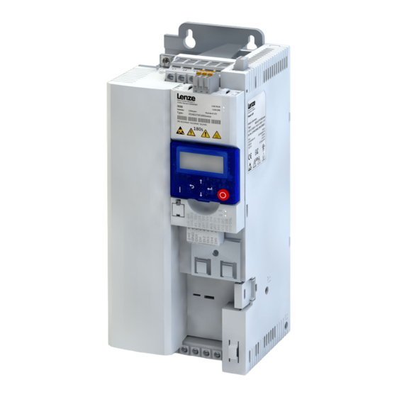
Seite 7: Produktbeschreibung
Produktbeschreibung Produktbeschreibung Netzanschluss X100 PE-Anschluss Relaisausgang X9 Netzwerk X2xx Op on Status-LEDs Netzwerk Schirmauflage CANopen/Modbus DIP-Schalter Baudrate und Busadresse Schni stelle X16 (CANopen/Modbus/PROFIBUS) Diagnosemodul Speichermodul X20 Status-LEDs Inverter Steuerklemmen X3 Standard I/O oder Applica on I/O Schirmauflage Steueranschlüsse IT-Schraube Sicherheitsmodul X1 Steckplatz IT-Schraube Motoranschluss X105... -
Seite 8: Montage
Montage Wichtige Hinweise Montage Wichtige Hinweise GEFAHR! Gefährliche elektrische Spannung Mögliche Folge: Tod oder schwere Verletzungen ▶ Alle Arbeiten am Inverter nur im spannungslosen Zustand durchführen. ▶ Nach dem Abschalten der Netzspannung mindestens 3 Minuten warten, bevor Sie mit den Arbeiten beginnen. -
Seite 9: Mechanische Installation
Montage Mechanische Installation Mechanische Installation Abmessungen i55AE 3 kW ... 5,5 kW Alle Maße in mm... - Seite 10 Montage Mechanische Installation Abmessungen i55AE 7,5 kW ... 11 kW Alle Maße in mm...
- Seite 11 Montage Mechanische Installation Abmessungen i55AE 15 kW ... 22 kW Alle Maße in mm...
-
Seite 12: Elektrische Installation
Montage Elektrische Installation 3-phasiger Netzanschluss 400 V Elektrische Installation 4.3.1 3-phasiger Netzanschluss 400 V Der Anschlussplan ist gültig für die Inverter I5xAExxxF. 3/N/PE AC 400 V … 3/PE AC 340 V ... 528 V 45 Hz ... 65 Hz CANopen Modbus PROFIBUS EtherCAT... -
Seite 13: 3-Phasiger Netzanschluss 400 V
Montage Elektrische Installation 3-phasiger Netzanschluss 400 V 4.3.1.1 Absicherungs- und Klemmendaten Inverter I55AE230F I55AE240F I55AE255F I55AE275F I55AE311F I55AE315F I55AE318F Leitungsinstallation nach EN 60204-1 Verlegeart Betrieb ohne Netzdrossel Schmelzsicherung Charakteristik gG/gL oder gRL Max. Bemessungsstrom Sicherungsautomat Charakteristik Max. Bemessungsstrom Betrieb mit Netzdrossel Schmelzsicherung Charakteristik gG/gL oder gRL... - Seite 14 Montage Elektrische Installation 3-phasiger Netzanschluss 400 V Inverter I55AE322F Leitungsinstallation nach EN 60204-1 Verlegeart Betrieb Schmelzsicherung Charakteristik Max. Bemessungsstrom Sicherungsautomat Charakteristik Max. Bemessungsstrom Betrieb mit Netzdrossel Schmelzsicherung Charakteristik gG/gL oder gRL Max. Bemessungsstrom Sicherungsautomat Charakteristik Max. Bemessungsstrom Fehlerstrom-Schutzschalter ≥ 300 mA, Typ B Netzanschluss Anschluss X100...
- Seite 15 Montage Elektrische Installation 3-phasiger Netzanschluss 480 V 4.3.2 3-phasiger Netzanschluss 480 V Der Anschlussplan ist gültig für die Inverter I5xAExxxF. 3/N/PE AC 480 V … 3/PE AC 340 V ... 528 V 45 Hz ... 65 Hz CANopen Modbus PROFIBUS EtherCAT PROFINET EtherNet/IP...
-
Seite 16: 3-Phasiger Netzanschluss 480 V
Montage Elektrische Installation 3-phasiger Netzanschluss 480 V 4.3.2.1 Absicherungs- und Klemmendaten Inverter I55AE230F I55AE240F I55AE255F I55AE275F I55AE311F I55AE315F I55AE318F Leitungsinstallation nach EN 60204-1 Verlegeart Betrieb ohne Netzdrossel Schmelzsicherung Charakteristik gG/gL oder gRL Max. Bemessungsstrom Sicherungsautomat Charakteristik Max. Bemessungsstrom Betrieb mit Netzdrossel Schmelzsicherung Charakteristik gG/gL oder gRL... - Seite 17 Montage Elektrische Installation 3-phasiger Netzanschluss 480 V Inverter I55AE322F Leitungsinstallation nach EN 60204-1 Verlegeart Betrieb ohne Netzdrossel Schmelzsicherung Charakteristik gG/gL oder gRL Max. Bemessungsstrom Sicherungsautomat Charakteristik Max. Bemessungsstrom Betrieb mit Netzdrossel Schmelzsicherung Charakteristik gG/gL oder gRL Max. Bemessungsstrom Sicherungsautomat Charakteristik Max.
-
Seite 18: Anschluss An Das It-Netz
Montage Elektrische Installation Anschluss an das IT-Netz 4.3.3 Anschluss an das IT-Netz ACHTUNG! Interne Bauteile haben Erdpotenzial, wenn die IT-Schrauben nicht entfernt werden. Folge: Die Überwachungseinrichtungen des IT-Netzes sprechen an. ▶ Vor dem Anschluss an ein IT-Netz unbedingt die IT-Schrauben entfernen. TX10 TX10... -
Seite 19: Canopen
(500 kBit/s) OFF 1 MBit/s Alle anderen Kombinationen Wert aus Parameter (500 kBit/s) Fettdruck = Lenze-Einstellung Das Netzwerk muss am physikalisch ersten und letzten Busteilnehmer mit einem 120 Ω-Widerstand abgeschlossen sein. An diesen Busteilnehmern den Schalter "R" auf ON stellen. -
Seite 20: Modbus
Wert aus Parameter Knotenadresse = 16 + 4 + 2 + 1 = 23 Knotenadresse > 247: Wert aus Parameter Fettdruck = Lenze-Einstellung Das Netzwerk muss am physikalisch ersten und letzten Busteilnehmer mit einem 120 Ω-Widerstand abgeschlossen sein. An diesen Busteilnehmern den Schalter "R" auf ON stellen. -
Seite 21: Elektrische Installation
Stationsadresse = 16 + 4 + 2 + 1 = 23 Stationsadresse = 126 und Stationsadresse = 127 nicht einstellen. Diese Stationsadressen sind ungültig. Fettdruck = Lenze-Einstellung Das Netzwerk muss am physikalisch ersten und letzten Busteilnehmer mit einem Widerstand abge- schlossen sein. -
Seite 22: Ethercat
Montage Elektrische Installation EtherCAT 4.3.7 EtherCAT Typische Topologien Linie Master Slave Device Bus-bezogene Information Bezeichnung EtherCAT Kommunikationsmedium Ethernet 100 MBit/s, Vollduplex Verwendung Anbindung des Inverter an ein EtherCAT-Netzwerk Anschlusstechnik RJ45 Statusanzeige 2 LEDs Anschlussbezeichnung In: X246 Out: X247 Netzwerk-Grundeinstellungen Mit dem Drehcodierschalter können Sie den EtherCAT‐Identifier einstellen. x 16 Einstellung Identifier... -
Seite 23: Ethernet/Ip
Montage Elektrische Installation EtherNet/IP 4.3.8 EtherNet/IP Typische Topologien Linie Baum Ring Scanner Adapter Bus-bezogene Information Bezeichnung EtherNet/IP Kommunikationsmedium Ethernet 10 MBit/s, 100 MBit/s, Halbduplex, Vollduplex Verwendung Anbindung des Inverter an ein EtherNet/IP-Netzwerk Anschlusstechnik RJ45 Statusanzeige 2 LEDs Anschlussbezeichnung X266, X267 Netzwerk-Grundeinstellungen Mit dem Drehcodierschalter können Sie das letzte Byte der IP-Adresse einstellen. -
Seite 24: Profinet
Montage Elektrische Installation PROFINET 4.3.9 PROFINET Typische Topologien Linie Baum Ring I/O-Controller Switch SCALANCE (MRP-fähig) I/O-Device Redundanzdomäne Bus-bezogene Information Bezeichnung PROFINET RT Kommunikationsmedium Ethernet 100 MBit/s, Vollduplex Verwendung Anbindung des Inverter an ein PROFINET-Netzwerk Anschlusstechnik RJ45 Statusanzeige 2 LEDs Anschlussbezeichnung X256, X257 Der Drehcodierschalter hat keine Funktion. -
Seite 25: Anschluss Sicherheitsmodul
Montage Elektrische Installation Anschluss Sicherheitsmodul 4.3.10 Anschluss Sicherheitsmodul 4.3.10.1 Wichtige Hinweise GEFAHR! Bei unsachgemäßer Installation der Sicherheitstechnik können Antriebe unkontrolliert anlaufen. Mögliche Folge: Tod oder schwere Verletzungen ▶ Nur qualifiziertes Personal darf Sicherheitstechnik installieren und in Betrieb nehmen. ▶ Alle Steuerungskomponenten (Schalter, Relais, SPS, ...) und der Schaltschrank müssen die Anforderungen der EN ISO 13849−1 und der EN ISO 13849−2 erfüllen. -
Seite 26: Anschlussplan
Montage Elektrische Installation Anschluss Sicherheitsmodul 4.3.10.2 Anschlussplan Passive Sensoren Aktive Sensoren Sicherheitsschaltgerät Aktiver Sensor - Beispiel Lichtgitter Passiver Sensor 4.3.10.3 Klemmendaten Beschreibung des Safety STO Anschlusses Anschluss Anschlusstyp Schraubklemme Min. Leitungsquerschnitt mm² Max. Leitungsquerschnitt mm² Abisolierlänge Anziehdrehmoment Benötigtes Werkzeug 0.4 x 2.5 Spezifikation Einheit min. -
Seite 27: Inbetriebnahme
Inbetriebnahme Wichtige Hinweise Inbetriebnahme Wichtige Hinweise WARNUNG! Fehlerhafte Einstellungen während der Inbetriebnahme können unerwartete und gefährliche Motor− und Anlagenbewegungen auslösen. Mögliche Folge: Tod, schwere Verletzungen oder Sachschäden ▶ Gefahrenbereich räumen. ▶ Sicherheitsvorschriften und Sicherheitsabstände einhalten. Vor dem ersten Einschalten Verhindern Sie Personenschäden und Sachschäden. Prüfen Sie vor dem Einschalten der Netzspannung: •... -
Seite 28: Erstes Einschalten / Funktionstest Mit Klemmensteuerung
Zielsetzung: Den am Inverter angeschlossenen Motor innerhalb kürzester Zeit zum Drehen bringen. Voraussetzungen: • Der angeschlossene Motor passt leistungsmäßig zum Inverter. • Die Parametereinstellungen entsprechen dem Auslieferungszustand (Lenze-Einstellung). 1. Vorbereitung: 1. Die Leistungsanschlüsse verdrahten. (Kapitel 4.3 Elektrische Installation) 2. Die Digitaleingänge X3/DI1 (Start/Stop), X3/DI3 (Drehrichtungsumkehr) und X3/DI4 (Frequenz-Preset 20 Hz) verdrahten. - Seite 29 1. Frequenz-Preset 1 wieder deaktivieren: X3/DI4 = LOW. 2. Inverter wieder stoppen: X3/DI1 = LOW. Der Funktionstest ist abgeschlossen. Die Inbetriebnahme der Antriebslösung ist in einer separaten Inbetriebnahmeanleitung beschrie- ben. Diese finden Sie im Internet in unserem Downloadbereich: http://www.lenze.com à Download...
-
Seite 30: Technische Daten
USA und Kanada (Anforderungen der CSA 22.2 No. 274) 0.25 kW … 22 kW (30 kW … 45 kW in Vorbereitung) Energieeffizienz Klasse IE2 EN 50598-2 Bezug: Lenze-Einstellung (Schaltfrequenz 8 kHz variabel) Schutzart IP20 EN 60529 Typ 1 NEMA 250 Berührschutz... - Seite 31 Technische Daten Normen und Einsatzbedingungen > 1 kW bei Netzstrom ≤ 16 A: ohne zusätzliche Maßnahmen Netzstrom > 16 A: Mit Netzdrossel EN 61000-3-12 Rsce: Kurzschlussleistungsverhältnis am oder Netzfilter, bei Auslegung für Anschlusspunkt der Maschine/Anlage zum Bemessungsleistung. Rsce ≥ 120 ist öffentlichen Netz zu erfüllen.
- Seite 32 Technische Daten 3-phasiger Netzanschluss 400 V 3-phasiger Netzanschluss 400 V Die Ausgangsströme gelten für diese Einsatzbedingungen: • Bei Schaltfrequenz 2 kHz oder 4 kHz: Umgebungstemperatur max. 45 °C. • Bei Schaltfrequenz 8 kHz oder 16 kHz: Umgebungstemperatur max. 40 °C.
-
Seite 33: 3-Phasiger Netzanschluss 400 V
Technische Daten 3-phasiger Netzanschluss 400 V Bemessungsdaten 6.2.1 Bemessungsdaten Inverter I55AE230F I55AE240F I55AE255F I55AE275F I55AE311F I55AE315F I55AE318F Bemessungsleistung 18.5 Netzspannungsbereich 3/PE AC 340 V ... 528 V, 45 Hz ... 65 Hz Netz-Bemessungsstrom ohne Netzdrossel 12.5 17.2 28.4 38.7 48.4 mit Netzdrossel 12.4 15.7... - Seite 34 Technische Daten 3-phasiger Netzanschluss 400 V Bemessungsdaten Inverter I55AE322F Bemessungsleistung Netzspannungsbereich 3/PE AC 340 V ... 528 V, 45 Hz ... 65 Hz Netz-Bemessungsstrom ohne Netzdrossel mit Netzdrossel 42.3 Ausgangsstrom 2 kHz 4 kHz 8 kHz 16 kHz 31.3 Verlustleistung Überstrom Zyklus 180 s Max.
- Seite 35 Technische Daten 3-phasiger Netzanschluss 480 V Bemessungsdaten 3-phasiger Netzanschluss 480 V Die Ausgangsströme gelten für diese Einsatzbedingungen: • Bei Schaltfrequenz 2 kHz oder 4 kHz: Umgebungstemperatur max. 45 °C. • Bei Schaltfrequenz 8 kHz oder 16 kHz: Umgebungstemperatur max. 40 °C.
-
Seite 36: 3-Phasiger Netzanschluss 480 V
Technische Daten 3-phasiger Netzanschluss 480 V Bemessungsdaten 6.3.1 Bemessungsdaten Inverter I55AE230F I55AE240F I55AE255F I55AE275F I55AE311F I55AE315F I55AE318F Bemessungsleistung 18.5 Netzspannungsbereich 3/PE AC 340 V ... 528 V, 45 Hz ... 65 Hz Netz-Bemessungsstrom ohne Netzdrossel 10.5 14.3 16.6 23.7 32.3 40.3 mit Netzdrossel 10.3... - Seite 37 Technische Daten 3-phasiger Netzanschluss 480 V Bemessungsdaten Inverter I55AE322F Bemessungsleistung Netzspannungsbereich 3/PE AC 340 V ... 528 V, 45 Hz ... 65 Hz Netz-Bemessungsstrom ohne Netzdrossel 47.4 mit Netzdrossel 35.3 Ausgangsstrom 2 kHz 40.4 4 kHz 40.4 8 kHz 40.4 16 kHz 26.9 Verlustleistung...
- Seite 76 © 02/2016 | 13507337 | 2.0 Lenze Drives GmbH Ö Postfach 10 13 52, D-31763 Hameln Breslauer Straße 3, D-32699 Extertal Germany HR Lemgo B 6478 +49 5154 82-0 Ü +49 5154 82-2800 Ø lenze@lenze.com Ù www.lenze.com Ú Lenze Service GmbH Û...