Lenze i500 Montageanleitung
Vorschau ausblenden
Andere Handbücher für i500:
- Montage- und einschaltanleitung (76 Seiten) ,
- Montageanleitung (12 Seiten) ,
- Montage- und einschaltanleitung (76 Seiten)

Verwandte Anleitungen für Lenze i500


Inhaltszusammenfassung für Lenze i500
- Seite 1 Montageanleitung | Mounting instructions i500 Diagnosemodule, Blindkappe i500 Diagnostic modules, blanking cover...
-
Seite 3: Inhaltsverzeichnis
Inhalt Inhalt Über dieses Dokument Dokumentenbeschreibung Produktbeschreibung Keypad USB-Modul WLAN-Modul Blindkappe Montage Montageschritte... -
Seite 4: Über Dieses Dokument
Dieses Zubehör kann unter den Einsatzbedingungen der zugeordneten Produkte betrieben werden. Abweichende oder zusätzliche Einsatzbedingungen sind hier aufgeführt. Dokumentenbeschreibung Informationen zur Verdrahtung und zur Inbetriebnahme finden Sie in der Montage- und Einschaltan- leitung des Inverters. Informationen und Hilfsmittel rund um die Lenze-Produkte finden Sie im Internet: http://www.lenze.com à Download... -
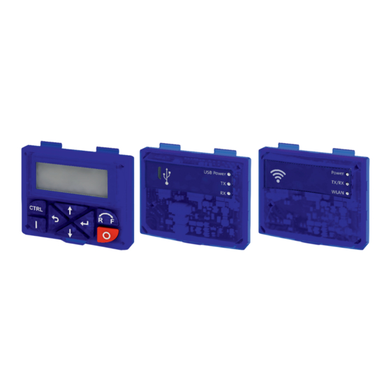
Seite 5: Produktbeschreibung
Produktbeschreibung Keypad Produktbeschreibung Keypad Parametrierung und Diagnose Über die Navigationstasten greifen Sie dank der intuitiven Bedienstruktur einfach und schnell auf die wich- tigsten Parameter zu. Entweder um Funktionen zu konfigurieren oder aktuelle Werte abzufragen. Parameter und Istwerte werden auf dem gut ablesbaren Display angezeigt. Funktion der Keypad-Tasten im Bedienmodus Taste Betätigung... - Seite 6 Produktbeschreibung Keypad Funktion der Keypad-Tasten im Parametriermodus Taste Betätigung Voraussetzung Aktion Kurz Lokale Keypad-Steuerung aktiv. Motor starten. Anzeige "LOC" Remote-Steuerung aktiv. Über Keypad ausgelösten Stopp aufheben. Anzeige "REM" Der Motor bleibt weiterhin gestoppt. Anzeige "KSTOP" Anzeige wechselt von "KSTOP" auf "STOP". Kurz Kein JOG-Betrieb Motor stoppen.
-
Seite 7: Usb-Modul
USB-Modul Schnittstelle zum PC Mit einer USB 2.0‑Anschlussleitung verbinden Sie den Inverter mit einem PC mit dem Lenze Engineering Tool »EASY Starter«. Mit dem »EASY Starter« konfigurieren Sie den Inverter über graphische Oberflächen. Sie erstellen Diagnosen mit Trend-Funktionen oder beobachten Parameterwerte. -
Seite 8: Wlan-Modul
WLAN-Modul Die drahtlose Schnittstelle Kommunizieren Sie drahtlos mit dem Inverter • über einen PC mit dem Lenze Engineering Tool »EASY Starter« oder • über die Lenze-Smart-Keypad-App für Android-Smartphones. Die App empfiehlt sich zur Anpassung von einfachen Anwendungen. Die übersichtliche Bedienoberfläche der App führt Sie intuitiv und sicher durch alle Menüs. -
Seite 9: Blindkappe
Produktbeschreibung WLAN-Modul Zusätzliche Konformitäten und Approbationen EN 301489-1 V2.1.1:2016 EN 301489-17 V3.1.1:2016 EN 300328 V2.1.1:2016 Part 15.107/15.109 ICES-003 Verbindungsdaten (Voreinstellung) IP-Adresse 192.168.178.1 SSID <Produkttyp>_<10-stellige Kennung> Passwort password WLAN-Modul Bestellcode Ausführung Reichweite im freien Umfeld: 100 m, Gegebenheiten am Einsatzort können die Reichweite I5MADW0000000S mindern. -
Seite 10: Montage
Montage Montageschritte Montage Montageschritte Die Montageschritte sind für alle Diagnosemodule und die Blindkappe gleich. Als Beispiel wird die Montage des USB-Moduls beschrieben. 1. Diagnosemodul in die oberen Befestigungsschlitze einhaken. Œ 2. Nach unten schwenken, bis es im unteren Befestigungsschlitz einrastet. ... - Seite 20 © 08/2017 | 13538913 | 5.0 Lenze Drives GmbH Ö Postfach 10 13 52, D-31763 Hameln Breslauer Straße 3, D-32699 Extertal Germany HR Lemgo B 6478 +49 5154 82-0 Ü +49 5154 82-2800 Ø lenze@lenze.com Ù www.lenze.com Ú Lenze Service GmbH Û...