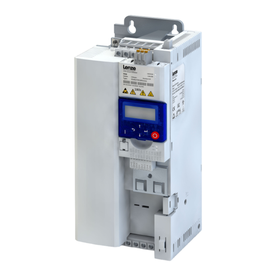
Lenze i500 Montageanleitung
Diagnosemodule, blindkappe
Vorschau ausblenden
Andere Handbücher für i500:
- Montage- und einschaltanleitung (76 Seiten) ,
- Montageanleitung (20 Seiten) ,
- Montage- und einschaltanleitung (56 Seiten)
Inhaltszusammenfassung für Lenze i500
- Seite 1 Montageanleitung Diagnosemodule, Blindkappe Diagnostic modules, Mounting Instructions blanking cover...
- Seite 2 Lesen Sie vor der Installation und Inbetriebnahme sorgfältig diese Dokumentation. ▶ Beachten Sie die Sicherheitshinweise! Informationen zur Verdrahtung und zur Inbetriebnahme finden Sie in der Montage- und Einschal- tanleitung des Inverters. Informationen und Hilfsmittel rund um die Lenze-Produkte finden Sie im Internet: http://www.lenze.com à Download...
-
Seite 3: Produktbeschreibung
Keypad USB-Modul Schnittstelle zum PC Mit einer USB 2.0‑Anschlussleitung verbinden Sie den Inverter mit dem Lenze Engineering Tool „EASY Star- ter“. Mit dem „EASY-Starter“ konfigurieren Sie den Inverter über graphische Oberflächen. Sie erstellen Diag- nosen mit Trend-Funktionen oder beobachten Parameterwerte. - Seite 4 Produktbeschreibung WLAN-Modul Die drahtlose Schnittstelle Kommunizieren Sie drahtlos mit dem Lenze Engineering Tool „EASY Starter“ oder der Lenze Smartphone- App für Android-Handys. Die App empfiehlt sich zur Anpassung von einfachen Anwendungen. Die übersichtliche Bedienoberfläche der App führt Sie intuitiv und sicher durch alle Menüs.
- Seite 5 Produktbeschreibung Blindkappe Schutz und Optik Die Blindkappe schützt die Anschlüsse und sorgt für eine einheitliche Optik, wenn kein anderes Modul auf- gesteckt ist. Bestellbezeichnung I5ZAA0000M Blindkappe...
-
Seite 6: Montage
Montage Montageschritte Montage Montageschritte Die Montageschritte sind für alle Diagnosemodule und die Blindkappe gleich. Als Beispiel wird die Montage des USB-Moduls beschrieben. 1. Diagnosemodul in die oberen Befestigungsschlitze einhaken. Œ 2. Nach unten schwenken, bis es im unteren Befestigungsschlitz einrastet. ... -
Seite 7: General Information
Please observe the safety instructions! You will find information on wiring and commissioning in the mounting and switch-on instructions of the inverter. Information and tools with regard to the Lenze products can be found on the Internet: http://www.lenze.com à Download... -
Seite 8: Product Description
USB module Interface to the PC The USB 2.0‑connecting cable is used to connect the inverter with the "EASY Starter" Lenze Engineering Tool. The "EASY Starter" serves to configure the inverter via graphical interfaces. They create diagnostics with trend functions or monitor parameter values. - Seite 9 Product description WLAN module The wireless interface Wireless communication with the "EASY Starter" Engineering Tool or the Lenze smartphone app for Android mobile phones. The app is recommended for adapting easy applications. The clearly arranged user interface of the app guides you intuitively and safely through all the menus.
- Seite 10 Product description Blanking cover Protection and optics The blanking cover protects the terminals and provides for a uniform optics if no other module is plugged Order designation I5ZAA0000M Blanking cover...
- Seite 11 Mounting Mounting steps Mounting Mounting steps The mounting steps are the same for all diagnostic modules and the blanking cover. This example shows the installation of the USB module. 1. Hook the diagnostic module into the upper mounting slots. Π2.
- Seite 12 © 10/2015 | 13497576 | 2.0 Lenze Drives GmbH Ö Postfach 10 13 52, D-31763 Hameln Breslauer Straße 3, D-32699 Extertal Germany HR Lemgo B 6478 +49 5154 82-0 Ü +49 5154 82-2800 Ø lenze@lenze.com Ù www.lenze.com Ú Lenze Service GmbH Û...


