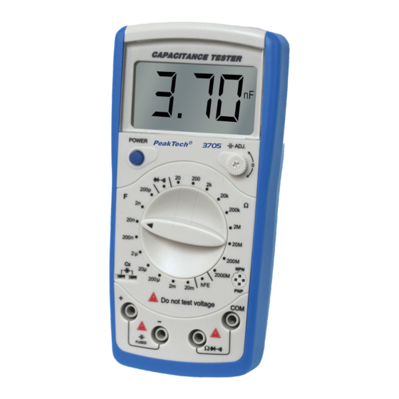
PeakTech 3705 Bedienungsanleitung
Kapazitätsmessgerät
Inhaltsverzeichnis
Quicklinks
5. Operation
5.1. General instructions
However, electrical noise or intense electromagnetic fields in
the
equipment
may
disturb
Measuring instruments will also respond to unwanted signals
that may be present within the measurement circuit. Users
should exercise care and take appropriate precautions to avoid
misleading results when making measurements in the
presence of electronic interference.
5.2. Capacitance
WARNING ! Discharge capacitor before trying to measure
it !
1. Set the Function/Range switch to the desired range
2. Insert the test leads directly into the socket or test leads
socket CX.
3. Read the capacitance directly from the display
Note
In lower range subtract residual offset reading from the result
with test leads opening.
WARNING !
Never apply an external voltage to socket damage to the
meter may result.
the
measurement
-31-
5.3. Resistance
WARNING !
Never apply an external voltage to the sockets damage to
the meters may result.
circuit.
1. Set the Function/Range switch to the desired range
2. Insert the red test lead into Ω
black test lead into COM-socket.
3. Read the resistance directly from the display
Note
*
The resistance in the test leads can diminish accuracy
on the lowest (200 Ω) range. The error is usually 0.1 to
0.2 Ω for a standard pair of test leads. To determine the
error, short the test leads together and then use the
(REL) Relative mode to automatically subtract the lead
resistance from resistance measurements.
*
For high resistance measurement (>1MΩ), it is normal
taking several seconds to obtain a stable reading.
5.4. Diode Test
WARNING !
To avoid damages to the Meter or to the devices under test,
disconnect circuit power and discharge all the high-voltage,
capacitors before measuring diodes and continuity.
. )))
socket and the
-32-
Inhaltsverzeichnis

Verwandte Anleitungen für PeakTech 3705


Inhaltszusammenfassung für PeakTech 3705
- Seite 1 5. Operation 5.3. Resistance WARNING ! Never apply an external voltage to the sockets damage to 5.1. General instructions the meters may result. However, electrical noise or intense electromagnetic fields in equipment disturb measurement circuit. 1. Set the Function/Range switch to the desired range Measuring instruments will also respond to unwanted signals that may be present within the measurement circuit.
- Seite 2 Testing Diodes Symbol Meaning Use the diode test to check diodes, transistors, and other The battery is low semiconductor devices. The diode test sends a current through the semiconductor junction. And then measures the voltage WARNING! drop across the junction. A good silicon junction drops To avoid false readings, which could lead to between 0,5 V and 0,8 V.
- Seite 3 When diode measurement been completed 1) LCD Display disconnect the connection between the testing clips and 2) Capacitance Zero Adjustment Switch the circuit under test and remove the testing clips and 3) Transistor Jack the circuit under test and remove the testing clips away 4) Resistance, Diode and Continuity Buzzer Input Terminal from the input terminals of the Meter.
-
Seite 4: Front View
5.6. Transistor hFE Measurement 4. Front View To measure transistor, set up the Meter as follows: 1. Check that the transistor is PNP or NPN type. 2. Insert the transistor to be measured to the corresponding Transistor Jack. 3. The Meter displays the tested transistor´s nearest value. Note: When transistor measurement has been completed, disconnect the connection between the testing clips and... - Seite 5 3.3 Continuity and Diodes 2. Remove the screw from the battery compartment, and separate the battery compartment from the case bottom. Function Range Resolution Overload Protection 3. Remove the battery from the battery compartment. Diode 250V 4. Replace the battery with a new 9V battery (NEDA 1604, Continuity 1 Ω...
- Seite 6 6.2. Replacing the Fuse WARNING ! Overload protection: 0,315A / 250V fuse To avoid electrical shock or arc blast, or personal injury or If the meter can not adjust to zero, you could damage to the Meter, use specified fuses ONLY in accordance use the tested values minus the open circuit with the following procedure.
-
Seite 7: Measuring Functions
Statutory Notification about the Battery Regulations Storage Temperature -20° C to + 50° C at max. 75% relative The delivery of many devices includes batteries, which for humidity (battery must be removed from example serve to operate the remote control. There also could meter) be batteries or accumulators built into the device itself. -
Seite 8: Specifications
2. SPECIFICATIONS Batteries, which contain harmful substances, are marked with the symbol of a crossed-out waste bin, Display 3½ digit 21 mm liquid crystal (LCD) with similar to the illustration shown left. an maximum reading of 1999 Under the waste bin symbol is the chemical symbol for the harmful Polarity automatic, positive implied, negative polarity... - Seite 9 We recommend to calibrate the unit again, after 1 year. Do not modify the equipment in any way ® Opening the equipment and service – and repair work © PeakTech 01/2011/Th/pt must only be performed by qualified service personnel Measuring instruments don’t belong to children hands.
- Seite 10 Comply with the warning labels and other info on the equipment. Always start with the highest measuring range when measuring unknown values. PeakTech 3705 ® Do not subject the equipment to direct sunlight or extreme temperatures, humidity or dampness. Do not subject the equipment to shocks or strong vibrations.
-
Seite 11: Safety Precautions
1. Safety Precautions 1. Instructions de sécurité This product complies with the requirements of the following Le présent appareil répond aux directives UE 2004/108/CEE European Community Directives: 89/336/EC (Electromagnetic (compatibilité électromagnétique) et 2006/95/CEE (basse Compatibility) and 73/23/EC (Low Voltage) as amended by tension) selon la définition dans le supplément 2004/22/CEE 93/68/EC (CE-Marking). - Seite 12 Avant de changer de fonction de mesure, découpler les câbles de contrôle ou bien la sonde de la commutation de mesurage. PeakTech 3705 ® Ne pas appliquer de sources de chaleur par le biais des entrées. En cas de non-respect, il y a risque de blessure et/ou d’endommager le multimètre.
- Seite 13 à la température ambiante (important lors nach Ablauf von 1 Jahr wird empfohlen. du passage d’une pièce froide à une pièce chaude et vice-versa) ® © PeakTech 01/2011/Th/pt Lors des mesures, ne dépassez jamais la plage de mesure réglée. Vous éviterez ainsi d’endommager l’appareil.
-
Seite 14: Spécifications Techniques
Nettoyez régulièrement le boîtier avec un chiffon Batterien, die Schadstoffe enthalten, humide et un nettoyant doux. N’utilisez pas de sind Symbol einer produits abrasifs décapants. durchgekreuzten Mülltonne Le présent appareil est seulement conçu pour des gekennzeichnet, ähnlich Symbol in der Abbildung links. Unter applications en intérieur. - Seite 15 Batterie einsetzen und Batteriefach mit der Schraube Affichage plage befestigen. excédée 1 est affiché ACHTUNG! Mesurage par Defekte Sicherung nur mit einer dem Originalwert zéro automatique entsprechenden Sicherung ersetzen (0,315 A/250 V). Affichage de l’état de la pile symbole pile apparaît si la tension de la pile Gesetzlich vorgeschriebene Hinweise...
-
Seite 16: Fonctions De Mesure
3. Fonctions de mesure Dazu wie beschrieben verfahren: 3.1. Mesures de capacité 1. Die Schraube an der Rückseite des Gerätes lösen Plage Résolution Précision Fréquence und Batteriefachdeckel abnehmen contrôle 2. Verbrauchte Batterie aus dem Batteriefach entnehmen 200 pF 0,1 pF 3. -
Seite 17: Wartung Des Gerätes
5.6.Transistortest La résistance propre aux câbles de contrôle peut influencer négativement la précision de mesure lors de la mesure de 1. Funktionswahlschalter in Stellung hFE drehen. petites résistances (plage 200 Ω). La résistance propre aux câbles de contrôle usuelles est situé entre 0,2 et 1 Ω. Pour 2. - Seite 18 4. Vue avant de l’appareil Wird ein Wert sowohl vor als auch nach dem Ver- Vertauschen der Polarität angezeigt, ist das Bauteil kurzgeschlossen und defekt. 5.5.Durchgangsprüfung 1. Funktions-/Bereichswahlschalter in Stellung ° drehen 2. Rote Prüfleitung an den Ω/ )))-Eingang und schwarze °...
- Seite 19 Achtung: Écran LCD Touche de remise à zéro pour fonction de capacité Vor Überprüfung der Diode, Bauteil bzw. Schaltungen unbedingt spannungslos schalten oder Diode aus der Prise femelle de contrôle pour le contrôle des transistors Schaltung auslöten. Zur Durchführung des Diodentests wie Prises femelles d’entrée pour le contrôle des beschrieben verfahren: résistances, des diodes et de continuité...
- Seite 20 5.3. Widerstandsmessungen Symbole Description ACHTUNG ! Affichage de l’état de la pile : Keine externen Spannungsquellen an die Eingangsbuchsen La pile est vide anschließen. Bei Anschluss externer Spannungsquellen an die ATTENTION ! Eingangsbuchsen besteht die Gefahr der Beschädigung des La pile manque de puissance et peut Gerätes.
- Seite 21 5. Messbetrieb 5. Mode de mesure 5.1. Allgemeines 5.1. Généralités Genaue Messergebnisse setzen entsprechende Mess- Des résultats de mesure précis présupposent des conditions bedingungen voraus. Bitte beachten Sie, dass Messungen in de mesure équivalentes. Veuillez considérer que les mesures der Nähe von elektromagnetischen Feldern oder starken réalisées à...
- Seite 22 5.3. Mesures de résistance Symbol Beschreibung ATTENTION ! Batteriezustandsanzeige: Ne pas brancher de sources de tension externes sur les prises Batterie ist leer femelles d’entrée. Cela risquerait en effet de détruire l’appareil. WARNUNG! Mangelnde Batterieleistung kann unpräzise 1. Choisir la plage de résistance désirée avec le sélecteur de Messergebnisse hervorrufen.
- Seite 23 5.4 Contrôle de diode 1) LCD-Anzeige 2) Nulleinstellungsknopf für Kapazitätsfunktion ATTENTION ! 3) Prüfbuchse für Transistorprüfung Ne pas brancher de sources de tension externes sur les prises 4) Eingangsbuchsen für Widerstands-, Dioden - und femelles d’entrée. Cela risquerait en effet de détruire l’appareil. Durchgangsprüfung mit Summer 5) Eingangsbuchsen für Kapazitätsmessungen Cette fonction permet de tester la continuité...
-
Seite 24: Vorderansicht Des Gerätes
4. Vorderansicht des Gerätes Si un dépassement est affiché sur l’écran, la diode est défectueuse ou bien les câbles de contrôle ne sont pas polarisés correctement. Si une valeur est affichée sur l’écran, la diode est conductrice et en bon état. La valeur affichée correspond à... -
Seite 25: Entretien De L'appareil
5.6. Contrôle des transistors Eigenwiderstand Prüfleitungen kann Messungen von kleinen Widerständen (200 Ω-Bereich) die 1. Placer le sélecteur de fonction sur la position hFE. Genauigkeit der Messung negativ beeinträchtigen. Der Eigenwiderstand üblicher Prüfleitungen liegt zwischen 2. Déterminer le type du transistor (NPN/PNP). Déterminer le 0,2...1 genauen Bestimmung... - Seite 26 3. Messfunktionen Procéder de la manière suivante : 1. Dévisser la vis à l’arrière de l’appareil et ôter le couvercle 3.1. Kapazitätsmessungen du compartiment à piles. Bereich Auflösung Genauigkeit Testfrequenz 2. Enlever les piles usées du compartiment à piles. 200 pF 0,1 pF 3.
- Seite 27 ATTENTION ! Überbereichs- anzeige 1 wird angezeigt Uniquement remplacer les fusibles défectueux par un fusible disposant de la même valeur que le fusible original Nullabgleich automatisch (0,315 A/250 V). Batteriezustands- anzeige Batteriesymbol erscheint bei ungenügender Indications légales obligatoires sur la réglementation Batteriespannung relative à...
-
Seite 28: Technische Daten
Säubern Sie das Gehäuse regelmäßig mit einem feuchten Stofftuch einem milden Reinigungsmittel. Benutzen Sie keine ätzenden Scheuermittel. Dieses Gerät ausschließlich für Innen- anwendungen geeignet. Vermeiden Sie jegliche Nähe zu explosiven und entflammbaren Stoffen. Öffnen Gerätes Wartungs – Reparaturarbeiten dürfen qualifizierten Service-Technikern durchgeführt werden. - Seite 29 Messbereich. vermeiden ® Beschädigungen des Gerätes. © PeakTech 01/2011/Th/pt Messungen von Spannungen über 35V DC oder 25V AC nur in Übereinstimmung mit den relevanten Sicherheitsbestimmungen vornehmen. Bei höheren Spannungen können...
- Seite 30 Schäden, durch Nichtbeachtung dieser Hinweise entstehen, sind von Ansprüchen jeglicher Art ausgeschlossen. maximal zulässige Eingangswerte unter keinen Umständen überschreiten (schwere Verletzungsgefahr und/oder Zerstörung des Gerätes) Nehmen Sie das Gerät nie in Betrieb, wenn es nicht völlig geschlossen ist. Defekte Sicherungen nur mit einer dem Originalwert entsprechenden Sicherung ersetzen.
-
Seite 31: Sicherheitshinweise
1. Sicherheitshinweise Dieses Gerät erfüllt die EU-Bestimmungen 2004/108/EG (elektromagnetische Kompatibilität) 2006/95/EG (Niederspannung) entsprechend der Festlegung im Nachtrag 2004/22/EG (CE-Zeichen). Überspannungskategorie II; Verschmutzungsgrad 2. CAT I: Signalebene, Telekommunikation, elektronische Geräte mit geringen transienten Überspannungen CAT II: Für Hausgeräte, Netzsteckdosen, portable Instrumente etc. CAT III: Versorgung durch unterirdisches... - Seite 32 PeakTech 3705 ® Bedienungsanleitung Kapazitätsmessgerät...