Herunterladen Inhalt Inhalt Diese Seite drucken
Sharp XV-Z2000 Anleitung
Vorschau ausblenden Andere Handbücher für XV-Z2000:
Inhaltsverzeichnis

Werbung

Verfügbare Sprachen

Verfügbare Sprachen

In the interests of user-safety (Required by safety regulations in some countries) the set should be re-
stored to its original condition and only parts identical to those specified should be used.
Im lnteresse der Benutzersicherheit (erforderliche Sicherheitsregeln in einigen Ländern) muß das Gerät in seinen
Originalzustand gebracht werden. Außerdem dürfen für die spezifizierten Bauteile nur identische Teile verwendet
werden.
SHARP CORPORATION
SERVICE MANUAL
SERVICE-ANLEITUNG
PROJECTOR
PROJEKTOR
XV-Z2000
MODELS
DT-400
MODELLE
This document has been published to be used for
after sales service only.
The contents are subject to change without notice.
XV-Z2000
DT-400
SY4C6XV-Z2000

Werbung

Inhaltsverzeichnis
loading

Inhaltszusammenfassung für Sharp XV-Z2000

  • Seite 1 XV-Z2000 DT-400 SERVICE MANUAL SERVICE-ANLEITUNG SY4C6XV-Z2000 PROJECTOR PROJEKTOR XV-Z2000 MODELS DT-400 MODELLE In the interests of user-safety (Required by safety regulations in some countries) the set should be re- stored to its original condition and only parts identical to those specified should be used.
  • Seite 2: Inhaltsverzeichnis

    XV-Z2000 DT-400 CONTENTS Page Page • SPECIFICATIONS ..........3 • BLOCK DIAGRAM .......... 88 • IMPORTANT SERVICE SAFETY • OVERALL WIRING DIAGRAM ....... 90 NOTES (for USA) ..........4 • WAVEFORMS ..........92 • NOTE TO SERVICE PERSONNEL ....6 •...
  • Seite 3: Specifications

    Europe) Video cable (QCNWGA001WJZZ:XV-Z2000, except U.S.A., Canada and DT-400), 21pin RCA conversion adaptor (QSOCZ0361CEZZ:XV-Z2000, for Europe) As a part of policy of continuous improvement, SHARP reserves the right to make design and specification changes for product improvement without prior notice. The performance specifica- tion figures indicated are nominal values of production units.
  • Seite 4: Important Service Safety Notes (For Usa)

    XV-Z2000 DT-400 IMPORTANT SERVICE SAFETY NOTES (for USA) Ë Service work should be performed only by qualified service technicians who are thoroughly familiar with all safety checks and servicing guidelines as follows: » Use an AC voltmeter with sensitivity of 5000 ohm per WARNING volt., or higher, sensitivity to measure the AC voltage...
  • Seite 5 XV-Z2000 DT-400 PRECAUTIONS A PRENDRE LORS DE LA REPARATION Ë Ne peut effectuer la réparation qu' un technicien spécialisé qui s'est parfaitement accoutumé à toute vérification de sécurité et aux conseils suivants. AVERTISSEMENT • Utiliser un voltmètre CA d'une sensibilité d'au moins 1.
  • Seite 6: Note To Service Personnel

    XV-Z2000 DT-400 NOTE TO SERVICE NOTE POUR LE PERSONNEL PERSONNEL D’ENTRETIEN 1 2 3 4 5 6 7 8 9 0 1 2 3 4 5 6 7 8 9 0 1 2 3 4 5 6 7 8 9 0 1 2 1 2 3 4 5 6 7 8 9 0 1 2 3 4 5 6...
  • Seite 7 XV-Z2000 DT-400 1 2 3 4 5 6 7 8 9 0 1 2 3 4 5 6 7 8 9 0 1 2 3 4 5 6 7 8 9 0 1 2 1 2 3 4 5 6 7 8 9 0 1 2 3 4 5 6...
  • Seite 8 XV-Z2000 DT-400 WARNING: High brightness light source, do not stare into the beam of light, or view directly. Be especially careful that children do not stare directly in to the beam of light. WARNING: TO REDUCE THE RISK OF FIRE OR ELECTRIC SHOCK, DO NOT EXPOSE THIS UNIT TO MOISTURE OR WET LOCATIONS.
  • Seite 9 XV-Z2000 DT-400 Precautions for using lead-free solder 1 Employing lead-free solder "PWBs" of this model employs lead-free solder. The LF symbol indicates lead-free solder, and is attached on the PWBs and service manuals. The alphabetical character following LF shows the type of lead-free solder.
  • Seite 10: Operation Manual

    XV-Z2000 DT-400 OPERATION MANUAL Projector Top View ON button Turn the power on. Power indicator STANDBY button Lamp indicator Put the projector into standby mode. Temperature warning indicator RESIZE button Switch the picture display (STRETCH, SIDE BAR, etc.). ZOOM/FOCUS button...
  • Seite 11: Power Indicator

    XV-Z2000 DT-400 About the Indicators on the Projector Power indicator Red on ... Normal (Standby) Green on ... Normal (Power on) Lamp indicator Green on ... Normal Green blinks ... The lamp is warming up or shutting down. Red on ... The lamp has been shut down abnormally or needs to be changed.
  • Seite 12 XV-Z2000 DT-400 Projector (Rear View) Terminals INPUT 2 terminal INPUT 4 terminal Component signals. Connect video equipment. INPUT 1 terminal Component signals. INPUT 3 terminal Connect video Digital input type switch equipment with an S-video terminal. INPUT 5/DIGITAL RS-232C terminal...
  • Seite 13: Remote Control

    XV-Z2000 DT-400 Remote Control STANDBY button Put the projector into standby ON button mode. Turn the power on. KEYSTONE button Enter the Keystone MENU button Correction mode. Display adjustment and setting screens. ENTER button Adjustment buttons Set items selected or ('/"/\/|)
  • Seite 14: Inserting The Batteries

    XV-Z2000 DT-400 Remote control sensor Front View 30° Usable Range 30° The remote control can be used to control the Remote control projector within the ranges shown in the signal illustration. transmitters 23' (7 m) 30° Note • The signal from the remote control can be re- Remote control flected off a screen for easy operation.
  • Seite 15 XV-Z2000 DT-400 Connection Pin Assignments DVI-I (INPUT 5) port : 29 pin connector • DVI Digital INPUT Pin No. Signal Pin No. Signal ∞ ∞ ∞ ∞ ∞ ∞ ∞ ∞ ∞ ∞ ∞ ∞ ∞ ∞ ∞ ∞ ∞ ∞...
  • Seite 16: Dimensions

    XV-Z2000 DT-400 DIMENSIONS Units: inches (mm) Rear View Side View Top View Side View (310) (55.05) Front View (99.95) (129.5) (129.5) (29.1) (30.9) Bottom View (44.1) (30.9)
  • Seite 17: Removing Of Major Parts

    XV-Z2000 DT-400 REMOVING OF MAJOR PARTS 1. Removing the lamp unit cover and the lamp unit 1-1. Loosen the lamp unit cover fixing screw, slide the lamp unit cover in allow direction and lift off the lamp unit cover. 1-2. Loosen 2 lamp unit fixing screws and lift off the lamp unit.
  • Seite 18 XV-Z2000 DT-400 3. Attaching the top body (For the screws to apply, refer back to "2. Removing the top body".) 3-1. Place the postcard over the lens barrel. 3-2. Place the top body in position. Make sure the four hooks are tightly caught.
  • Seite 19 XV-Z2000 DT-400 5. Removing the optical mechanism unit 5-1. Remove the fixing screw from the PWB bracket. 5-2. Remove 2 fixing screws for the ballast output socket, and remove the ballast output socket. 5-3. Remove 5 fixing screws for the optical mechanism unit, and remove the optical mechanism unit.
  • Seite 20 XV-Z2000 DT-400 7. Removing the power/ballast unit 7-1. Remove the fixing screw for the rear-R/C PWB. 7-2. Remove 4 fixing screws, 4 WH bosses and the edge saddle for the ballast unit. 7-3. Remove 11 fixing screws and 5 WH bosses for the power unit.
  • Seite 21 XV-Z2000 DT-400 9. Fixing the earth shield 9-1. Install the four nuts. 9-2. Fit the reinforcement (bracket-A) in position. 9-3. Place the earth shield (L) as specified. 9-4. Fit the reinforcement (bracket-B) in position. 9-5. Tighten up the four M3 screws.
  • Seite 22: Resetting The Total Lamp Timer

    The lamp life (percentage) can be checked with the on-screen display. I Purchase a replacement lamp of type AN-K2LP from your place of purchase, nearest Sharp Projector Dealer or Service Center.
  • Seite 23 Blocked air intake Temperature The internal • Take the projector to your nearest Red on warning temperature is • Cooling fan break- Sharp Authorized Projector Dealer (Standby) indicator abnormally high. down or Service Center for repair. • Internal circuit failure • •...
  • Seite 24: The Optical Unit Outline

    XV-Z2000 DT-400 THE OPTICAL UNIT OUTLINE Layout for proper setup of the optical components and parts (top view) (Schematic diagram) Reflection mirror Projection lens Color wheel Lamp Field lens UV Filter Illumination lenses 1 Illumination lenses 2 Item Function Lamp Light source.
  • Seite 25 XV-Z2000 DT-400 Air Flow After replacing the DMD, if shading is present on the screen as shown in Figure 1, adjust the lighting area of the DMD by turning the adjustment screws for the optical engine. 1. Loosen the fixing screw for the adjustment lever 1. Adjust the lighting area by adjustment lever 2 and then tighten the fixing screw for the adjustment lever 1.
  • Seite 26: Electrical Adjustment

    XV-Z2000 DT-400 ELECTRICAL ADJUSTMENT Adjusting point Adjusting conditions Adjusting procedure Initialization of 1. Turn on the power (the 1. Carry out the following setting. EEPROM lamp lights up) and warm Using the remote controller or press S2002 to up the system for 15 min- enter the process mode, and execute SS2 on SS utes.
  • Seite 27 XV-Z2000 DT-400 Adjusting point Adjusting conditions Adjusting procedure B-Bright / B- 1. Group: AD 1. Observe the 0% window pattern chromaticity on Contrast Subject: B-BRIGHT CA100. (Black level) 2. Starting with a bit dropout screen, vary the B- B-CONTRAST Bright setting until the bright blue "y" setting turns (White level) toward the black tone and stays there.
  • Seite 28 XV-Z2000 DT-400 Adjusting point Adjusting conditions Adjusting procedure DTV B-Bright/ 1. Group: DTV 1. Observe the 0%black window pattern chroma- Contrast Subject: B-BRIGHT ticity on CA100. Adjustment (Black level) 2. Starting with a bit dropout screen, vary the Bright B-CONTRAST setting until the bright blue "y"...
  • Seite 29 XV-Z2000 DT-400 Adjusting point Adjusting conditions Adjusting procedure DVD White 1. Feed the component 75% 1. Adjust the white balance by controlling R-GAIN and balance gray scale signal. B-GAIN. (Auto 2. Group: PIXEL (Adjust x=298 and y=319.) adjustment) Subject:R-GAIN (R)
  • Seite 30 XV-Z2000 DT-400 * Precautions in setting up the DMD (Digital Micromirror Device) unit Before connecting the formatter PWB to the optical engine, take the following steps. Look at the voltage rank marking that is on the DMD itself. Referring to this marking, set the DIP switches on the formatter PWB. And connect this PWB to the optical engine.
  • Seite 31 XV-Z2000 DT-400 Calling and quitting the process mode with the control keys on this model. ∗ Although it is possible for the process OUT to exit using the process menu, the IN/OUT toggle command is also available considering the existing specification.
  • Seite 32 XV-Z2000 DT-400 Adjustment mode process menu 2 second layer Initial Value second layer Initial Value VERSION Build R-Bright Boot Code G-Bright Config B-Bright RomCode R-Contrast G-Contrast B-Contrast EXIT EXIT Index Delay SS3 EU R-Bright SS4 US G-Bright SS5 JPN B-Bright...
  • Seite 33: Troubleshooting Table

    XV-Z2000 DT-400 TROUBLESHOOTING TABLE Checking the basic operation Does the power LED light up or flash in Go to "Checking the power supply system" red or green? and "Checking the power unit". Does the set function with its keys or the Go to "Checking the peripheral circuits of...
  • Seite 34 XV-Z2000 DT-400 Checking the power supply system Is 13V outputted to pins (9) and (11) of Go to "Checking the power unit". P1707? Is 6V outputted to pins (1) and (3) of Go to "Checking the power unit". P1707? Is the connector of P1707 fully inserted? Replace the thermal fuse.
  • Seite 35 XV-Z2000 DT-400 Checking the power unit Is each connector of the power unit Securely insert the connectors. fully inserted? Is the lamp door closed completely? Fix the lamp door with screws. Replace the bimetal switch or restore Is the bimetal broken? by pressing the red button.
  • Seite 36 XV-Z2000 DT-400 Checking the peripheral circuits of the microprocessor Are the voltages of approx. 3.3V and 2.5V Go to "Checking the power supply applied to both ends of C8001 and C8056 system". respectively? Are the oscillations of 133MHz and Check X8001, X8003 and their peripheral 74.25MHz outputted from pin (3) of...
  • Seite 37 XV-Z2000 DT-400 Checking the lamp light-up Does each cooling fan Check the power supply circuit function? or fan circuit on the main circuit. ABNORMAL Go to "Checking the Check Q9401 to Q9403, Is the rotating sound of the peripheral circuits of...
  • Seite 38 XV-Z2000 DT-400 » Formatter Unit Troubleshooting Display in trouble Equally spaced white or Screen with spectral black vertical stripes colors Black screen Miscellaneous Black horizontal band Color production of R, G and B is not correct. Adjustment by "Process Are the contact terminals...
  • Seite 39 XV-Z2000 DT-400 Checking the digital input Input the digital signal from INPUT5. Select digital with the keys on the main body or the remote control. End. Is picture outputted? Is the picture disturbed? Check between the input terminals Is the signal coming to pins (10)- and IC502.
  • Seite 40 XV-Z2000 DT-400 Checking the Component Send component signals to INPUT1 or INPUT2. Use keys on the main unit or remote control to select INPUT1 or INPUT2. Is video signal inputted into pins (3) to (5) of IC3102 at the time of INPUT1 selection, and...
  • Seite 41 XV-Z2000 DT-400 Checking the Video Input Feed the composite video signal to INPUT 4. Select INPUT 4 using the End. set's key or the remote controller. Is synchronized signal Does the picture appear? Is the picture disturbed? coming to pins (28) and...
  • Seite 42 XV-Z2000 DT-400 Checking the SOG Circuit Measure the pin (7) of IC5001 with an oscilloscope. Is the composite synchronized The SOG circuit is normal. signal regenerated at proper timing? End. Measure the pin (2) of Q5001 with an oscilloscope. Check Q3110 and its...
  • Seite 43 XV-Z2000 DT-400 Checking the S terminal input. Input the S terminal (Y, C) signal to INPUT 3. Select INPUT 3 with the keys on the main body or the remote controller. Does the picture appear? Is the picture disturbed? End.
  • Seite 44 XV-Z2000 DT-400 Checking the Sync Signal Is the horizontal synchronized signal on pin (6) of IC6003? Is the vertical synchronized signal Check the of the signal input part. on pin (6) of IC6009? Is the synchronized signal Check each IC and their peripheral outputted from IC5009, IC5005, circuits.
  • Seite 45 XV-Z2000 DT-400 Checking RS-232C Communication is disabled even though connecting the control PC and projector with a RS-232C cable. Is the connecting cable connected Replace the connecting cable. correctly? (cross cable) Is there any signal at pin (8) of IC8002? Check SC3501, R2039 and their peripheral circuits.
  • Seite 46 XV-Z2000 DT-400 Checking the IRIS, FOCUS and ZOOM motors Do all the motors function? Check the optical mechanism. Check the B+6V input line, IC8204 Is 3.3V of IC8204 outputted as and its peripheral circuits. specified? Check pins (16) and (17) of...
  • Seite 47: Technische Daten

    Video-Kabel, Linsenkappe (am Gehäuse befestigt), Bedienungsanleitung Ersatzteile Lampeneinheit (Lampe/Gehäusemodul) (AN-K2LP), Fernbedienung (RRMCGA334WJSA), AA-Batterien, Netzkabel (QACCDA007WJPZ:XV-Z2000 für USA, Kanada und DT-400) (für Europa, ausgenommen Großbritannien) (QACCVA011WJPZ:XV-Z2000 für Europa, ausgenommen Großbritannien) (QACCBA036WJPZ:XV-Z2000 für Großbritannien,Hongkong und Singapur) (QACCLA018WJPZ:XV-Z2000 für Australien und Neuseeland)21-Pin RCA- Konvertierungsadapte (QSOCZ0361CEZZ:XV-Z2000 für Europe), Video-Kabel...
  • Seite 48: Hinweise Für Das Wartungspersonal

    XV-Z2000 DT-400 HINWEISE FÜR DAS WARTUNGSPERSONAL 1 2 3 4 5 6 7 8 9 0 1 2 3 4 5 6 7 8 9 0 1 2 3 4 5 6 7 8 9 0 1 2 1 2 3 4 5 6 7 8 9 0 1 2 3 4 5 6...
  • Seite 49: Vorsichtsmaßregeln Für Bleifreien Lötzinn

    XV-Z2000 DT-400 Vorsichtsmaßregeln für bleifreien Lötzinn 1 Verwendung von bleifreiem Lötzinn Bei den Platinen für dieses Modells wird bleifreies Lot verwendet. Das Symbol LF kennzeichnet bleifreies Lot und findet sich an den Platinen und in den Wartungshandbüchern. Der Buchstabe hinter LF bezieht sich auf die Art des bleifreien Lots.
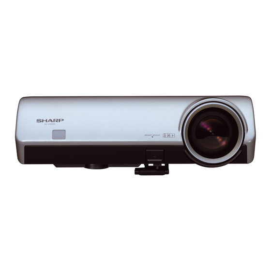
  • Seite 50: Bedienungsanleitung

    XV-Z2000 DT-400 BEDIENUNGSANLEITUNG Projektor Draufsicht ON-Taste Schaltet die Stromversorgung ein. Netz-Anzeige STANDBY-Taste Lampen-Anzeige Schaltet den Projektor in den Standby-Modus. Temperaturwarn- Anzeige RESIZE-Taste Für das Umschalten der Bildanzeige (STRECKEN, SEITENBALKEN, usw.). ZOOM/FOCUS-Taste Für das Einstellen der ENTER-Taste projizierten Bildgröße oder Für das Einstellen der das Einstellen des Fokus.
  • Seite 51: Informationen Über Die Anzeigen Des Projektors

    XV-Z2000 DT-400 Informationen über die Anzeigen des Projektors Netz-Anzeige Rot leuchtend ... Normal (Standby) Grün leuchtend ... Normal (Eingeschaltet) Lampen-Anzeige Grün leuchtend ... Normal Grün blinkend ... Die Lampe wird aufgewärmt oder wird ausgeschaltet. Rot leuchtend ... Die Lampe wurde auf unnormale Weise ausgeschaltet oder muss ausgewechselt werden.
  • Seite 52: Projektor (Rückansicht)

    XV-Z2000 DT-400 Projektor (Rückansicht) Anschlüsse Beachten Sie die Erläuterungen unter „INPUT (EINGANG)-Anschlüsse und Hauptausrüstung zum Anschließen“ . INPUT 2-Anschluss Anschluss für INPUT 4-Anschluss Komponentensignale. Anschluss für ein Videogerät. INPUT 1-Anschluss Anschluss für INPUT 3-Anschluss Komponentensignale. Anschluss für ein Videogerät Digitaler Eingangstyp-...
  • Seite 53: Fernbedienung

    XV-Z2000 DT-400 Fernbedienung STANDBY-Taste Schaltet den Projektor in den ON-Taste Standby-Modus. Schaltet die Stromversorgung ein. KEYSTONE-Taste Für das Aktivieren des Trapezverzerrungs- MENU-Taste Korrekturmodus. Für die Anzeige des Justierungs- und Einstellungsbildschirms. ENTER-Taste Einstelltasten Für das Einstellen der ausgewählten ('/"/\/|) oder eingestellten Menüpunkte.
  • Seite 54: Vorderansicht

    XV-Z2000 DT-400 Fernbedienungssensor Vorderansicht 30° Reichweite 30° Der Projektor kann mittels der Fernbedienung innerhalb der in der Abbildung dargestellten Signalsender für Fernbedienung Bereiche gesteuert werden. 30° Hinweis • Das Signal von der Fernbedienung kann für eine Fernbedienung einfache Bedienung von der Bildwand reflektiert werden.
  • Seite 55: Verbindungs-Pin-Zuweisungen

    XV-Z2000 DT-400 Verbindungs-Pin-Zuweisungen DVI-I (INPUT 5)-Anschluss: 29-pol. Stecker • DVI-Digital-Eingang Pin Nr. Signal Pin Nr. Signal ∞ ∞ ∞ ∞ ∞ ∞ ∞ ∞ ∞ ∞ ∞ ∞ ∞ ∞ ∞ ∞ ∞ ∞ T.M.D.S.-Daten 2- Zündkerzenerkennung T.M.D.S.-Daten 2+ T.M.D.S.-Daten 0- ∞...
  • Seite 56: Abmessungen

    XV-Z2000 DT-400 ABMESSUNGEN Einheiten: mm Ansicht von hinten Ansicht von Ansicht von Ansicht von der Seite oben der Seite 55,05 Ansicht von vorne 99,95 129,5 129,5 29,1 30,9 Ansicht von unten 44,1 30,9...
  • Seite 57: Entfernen Der Hauptteile

    XV-Z2000 DT-400 ENTFERNEN DER HAUPTTEILE 1. Ausbau der Lampentür und der Lampeneinheit 1-1. Die Lampentür-Befestigungsschraube herausdrehen, dann die Lampentür abnehmen. 1-2. Die 2 Lampeneinheits-Befestigungsschrauben herausdrehen, dann die Lampeneinheit abheben. Lampeneinheit Lampentür 2. Ausbau des oberen Gehäuses 2-1. Eine Postkarte oder ein dickes papier unter dem objektivtubus einzuführen.
  • Seite 58: Ausbau Der Hauptleiterplatteneinheit Und Der Peripheren Einheiten

    XV-Z2000 DT-400 3. Anbringen der oberen Gehäuses (Für die geeigneten Schrauben ist auf den Abschnitt "2. Aubau des oberen Gehäuses" Bezug zu nehmen.) 3-1. Die Postkarte über dem Objektivtubus einführen. 3-2. Die obere Gehäuse aufsetzen. Sicherstellen, daß die vier Haken gut einrasten.
  • Seite 59: Ausbau Der Optischen Laufwerkeinheit

    XV-Z2000 DT-400 5. Ausbau der optischen Laufwerkeinheit 5-1. Die Befestigungsschrauben für die Halterung. 5-2. Die zwei Sperrschrauben vom Lampenfassung entfernen. 5-3. Die 5 Befestigungsschrauben für die optische Laufwerkeinheit herausdrehen. 5-4. Den Kanal abnehmen. 5-5. Die Lautsprecherhalter abnehmen. Kanal Optische Laufwerkeinheit...
  • Seite 60: Ausbau Der Peripheren Einheiten

    XV-Z2000 DT-400 7. Ausbau der Vorschaltgerät/Netz-Einheit 7-1. Die Befestigungsschraube für die hintere R/C-einheit herausdrehen. 7-2. Die 4 Befestigungsschrauben, 4 WH-Naben und den Randhalter für die Vorschaltgerätteil entfernen. 7-3. Die 11 Befestigungsschrauben und 5 WH-Naben für das Netzteil entfernen. 7-4. Die 4 Befestigungsschrauben für das Gebläse herausdrehen.
  • Seite 61: Befestigen Der Erdungsplatte

    XV-Z2000 DT-400 9. Befestigen der Erdungsplatte 9-1. Die vier Muttern anbringen. 9-2. Die Verstärkung (Halterung A) aufsetzen. 9-3. Die Erdungsplatte wie gezeigt ansetzen. 9-4. Die Verstärkung (Halterung B) aufsetzen. 9-5. Die vier M3-Schrauben festziehen. 9-6. Die vier M4-Schrauben festziehen. 9-7. Die Erdungsplatte wie gezeigt ansetzen.
  • Seite 62: Rückstellun Des Lampen-Timers

    Sie eine deutliche Verschlechterung der Bild- und Farbqualität feststellen. Die Lampenlebensdauer (Prozentsatz) kann auf der Bildschirmanzeige überprüft werden. I Erwerben Sie über einen Sharp-Projektor-Händler oder Kundendienstbetrieb in Ihrer Nähe eine Lampe des Typs AN-K2LP. I Die Warnanzeigen (ON/STANDBY-Taste, Lampen-Anzeige und Temperatur-Warnanzeige) auf dem Projektor weisen auf Funktionsstörungen hin.
  • Seite 63 XV-Z2000 DT-400...
  • Seite 64: Beschreibung Der Optik-Einheit

    XV-Z2000 DT-400 BESCHREIBUNG DER OPTIK-EINHEIT Erläuterungen für das korrekte Setup der optischen Komponenten und Baugruppen (An- sicht von oben) (Schematische Darstellung) Reflektorspiegel Projektionslinse Farbrad Lampe Feldlinse UV-Filter Stab Beleuchtungslinsen 1 Beleuchtungslinsen 2 Objekt Funktion Lampe Lichtquelle. Gleichstrom-Hochdruck-Quecksilberlampe Farbrad Teilt durch den Farbfilter das Licht aus der Lichtquelle in R, G, B und W auf.
  • Seite 65 XV-Z2000 DT-400 Luftfluß Wenn nach dem Austausch von DMD eine Abschattung auf der Leinwand erscheint (siehe Abbildung 1), den Beleuchtungsbereich von DMD einstellen, indem man die Einstellschrauben für den optischen Motor dreht. 1. Die Befestigungsschraube für den Einstellhebel 1 lösen. Den Beleuchtungsbereich mit dem Einstellhebel 2 einstellen, dann die Befestigungsschraube für den Einstellhebel 1 anziehen.
  • Seite 66: Elektrische Einstellung

    XV-Z2000 DT-400 ELEKTRISCHE EINSTELLUNG Einstellpunkt Einstellbedingungen Einstellverfahren Initialisieren 1. DieBetriebsstromversor- 1. Die folgende Einstellung ausführen. Das von EEPROM gung einschalten (die Fernbedienungsteil verwenden oder S2002 Lampe leuchtet auf), und drücken, um auf Prozessmodus zu schalten, und das System 15 Minuten SS2 im SS-Menü...
  • Seite 67 XV-Z2000 DT-400 Einstellpunkt Einstellbedingungen Einstellverfahren G-Helligkeit/G- 1. Gruppe: AD 1. D i e 0 % - F e n s t e r - C h r o m a t i k v o n C A 1 0 0...
  • Seite 68 XV-Z2000 DT-400 Einstellpunkt Einstellbedingungen Einstellverfahren DTV-Helligkeit/ 1. Gruppe: DTV 1. Den festen Wert prüfen. Kontrast- Gegenstand:BRIGHT Kontrast: 5 Einstellung (Schwarzpegel) Helligkeit: 55 CONTRAST (Weißpegel) DTV-Helligkeit/ 1. D a s 4 8 0 P 1 0 0 % / 0 % 1.
  • Seite 69 XV-Z2000 DT-400 Einstellpunkt Einstellbedingungen Einstellverfahren DTV-Helligkeit/ 1. D a s 4 8 0 P 1 0 0 % / 0 % 1. Die 0%-Schwarz-Fenster-Chromatik von CA100 Kontrast Schwarz/Weiß-Fenster- beobachten. Mustersignal anlegen. 2. Beginnend mit einem Bit-Bildschirmaussetzer ist 2. Gruppe: DTV...
  • Seite 70 XV-Z2000 DT-400 Einstellpunkt Einstellbedingungen Einstellverfahren 1. Gruppe: VIDEO VIDEO-Farbton 1. Die festen Werte prüfen. Gegenstand: N-Farbton N-Farbton: 8 P-Farbton P-Farbton: 4 S-Farbton S-Farbton: 4 1. Gruppe: VIDEO VIDEO- 1. Die festen Werte prüfen. Gegenstand: N-Farbe Farbsättigungs- N-Farbe: 7 P-Farbe pegel...
  • Seite 71 XV-Z2000 DT-400 * Vorsichtsmaßregeln bei Einrichtung der DMD (Digital Micromirror Device)-Einheit Vor dem Anschließen der Formatierleiterplatte an der Optikengine die folgenden Schritte ausführen. Die Spannungsrangmarkierung am DMD selber beachten. Unter bezug auf diese Markierung die DIP-Schalter an der Formatierleiterplatte einstellen. Dann diese Leiterplatte an die Optikengine anschließen.
  • Seite 72 XV-Z2000 DT-400 1. Aktivieren und Deaktivieren des Prozeßmodus unter Verwendung der Steuertasten dieses Modells. ∗ Für den Prozess OUT ist es möglich, unter dem Prozessmenü zu verlassen, jedoch ist auch der IN/OUT- Umschaltbefehl mit Rücksicht auf die vorhandene Spezifikation verfügbar.
  • Seite 73 XV-Z2000 DT-400 Prozeßmenü 2 2. Schicht Ausgangswert 2. Schicht Ausgangswert VERSION Build R-Bright Boot Code G-Bright Config B-Bright RomCode R-Contrast G-Contrast B-Contrast EXIT EXIT Index Delay SS3 EU R-Bright SS4 US G-Bright SS5 JPN B-Bright SS6 CHIN R-Contrast EXIT G-Contrast...
  • Seite 74: Fehlersuchtabelle

    XV-Z2000 DT-400 FEHLERSUCHTABELLE Überprüfung der grund-legenden Funktionen Ist die POWER LED eingeschaltet, oder Zu den Abschnitten "Überprüfen des NEIN blinkt sie rot oder grün? Stromversorgungssystems" und "Überprüfen der Energieversorgung" gehen. Kann das Gerät mit der Einschalttaste oder Mit dem Abschnitt "Überprüfung der NEIN über die Fernbedienungseinheit...
  • Seite 75 XV-Z2000 DT-400 Überprüfung des Stromversorgungs- systems NEIN Wird 13V dem Stift (9) und (11) von Mit dem Abschnitt "Überprüfung des P1707 zugeführt? Netzteils" fortfahren. NEIN Wird 6 V dem Stift (1) und (3) von P1707 Mit dem Abschnitt "Überprüfung des zugeführt?
  • Seite 76 XV-Z2000 DT-400 Überprüfen des Netzteils NEIN Sind die Anschlüsse des Netzteils fest Den Anschluss fest einsetzen. eingesetzt? NEIN Ist die Lampentür vollständig Die Lampentür vollständig mit Schrauben geschlossen? schließen. Den Bimetall-Schalter ersetzen oder die NEIN Ist das Bimetall durchgebrannt? rote Taste zum Wiederherstellen drücken.
  • Seite 77 XV-Z2000 DT-400 Überprüfung der peripheren Schaltkreise des Mikroprozessors NEIN Liegen ca. 3,3 V und ca. 2,5 V an den Mit dem Abschnitt "Überprüfung des beiden Enden von C8001 bzw. C8056 an? Stromversorgungssystems" fortfahren. NEIN Werden die Oszillationen von 133 Hz und...
  • Seite 78 XV-Z2000 DT-400 Überprüfung der Lampenfunktion NEIN Laufen die Kühlgebläse? Den Stromversorgungskreis oder Gebläse- Schaltkreis am Hauptschaltkreis überprüfen. FEHLERHAFT Q9401-Q9403, IC9401 Mit dem Abschnitt NEIN Wird das Betriebsgeräusch (Motortriber-IC) und die "Überprüfung der des Farbrades gehört? peripheren schaltkreise peripheren Schaltkreise überprüfen.
  • Seite 79 XV-Z2000 DT-400 » Formatiereinheit-Störungssuche Störung an Display Gleichmäßig verteilte Bildschirm mit weiße oder schwarze Spektralfarben Schwarzer Bildschirm Verschiedenes senkrechte Streifen Farbproduktion bei R, G Schwarzer horizontaler und B ist nicht korrekt. Balken. Einstellung mit Sind die Bucsen Sind die Buchsen "Prozessmenü"→"DLP"...
  • Seite 80 XV-Z2000 DT-400 Überprüfen des Digitaleingangs Das Digitalsignal vom INPUT5 zuführen. Das Digitalsignal mit den Tasten am Gerät oder auf der Fernbedienung anwählen. NEIN Ende Wird ein Bild ausgegeben? Liegen Bildstörungen vor? NEIN Zwischen den NEIN Wird das Signal den Stiften (10)- Eingangsanschlüssen und dem...
  • Seite 81 XV-Z2000 DT-400 Überprüfen der Komponenten Komponenten-Signale an INPUT1 oder INPUT2 weiterleiten. Die Tasten am Gerät oder auf der Fernbedienung benutzen, um INPUT1 oder INPUT2 anzuwählen. Wird das zum Zeitpunkt der INPUT1-Wahl den Stiften (3) bis (5) von IC3102 zugeführte NEIN...
  • Seite 82 XV-Z2000 DT-400 Prüfen des Videoeingangs Das FBAS-Videosignal an INPUT4 einspeisen. INPUT4 mit den Ende. Tasten am Gerät oder an der Fernbedienung wählen. NEIN Liegt das synchronisierte Erscheint das Bild? Ist das Bild gestört? Signal an den Stiften (28) NEIN und (29) von IC3102 an?
  • Seite 83 XV-Z2000 DT-400 Prüfen der SOG-Schaltung Den Stift (7) von IC5001 mit einem Oszilloskop prüfen. Wird das FBAS-Signal mit richtiger Die SOG-Schaltung ist normal. Zeitgabe regeneriert? Ende. NEIN Den Stift (2) von Q5001 mit einem Oszilloskop prüfen. NEIN NEIN Q3110 und die peripheren Ist das Y-Signal einschließlich Syn-...
  • Seite 84 XV-Z2000 DT-400 Prüfung des Eingangs der S- Klemme. Das S-Klemmen-Signal (Y, C) von INPUT3 eingeben. INPUT3 mit den Tasten am Hauptgerät oder an der Fernbedienung wählen. NEIN Erscheint das Bild? Ist das Bild gestört? Ende. NEIN IC3105 und die Werden die Videosignale von...
  • Seite 85 XV-Z2000 DT-400 Prüfen des Sync-Signals Wird das horizontal synchronisierte NEIN Signal auf Stift (6) von IC6003 ausgegeben? Wird das vertikal synchronisierte NEIN Die Leiterplatte des Signal auf Stift (6) von IC6009 Signaleingangsteils prüfen. ausgegeben? Wird das synchronisierte Signal von NEIN...
  • Seite 86 XV-Z2000 DT-400 Überprüfung von RS-232C Eine Kommunikation ist nicht möglich, selbst wenn der Steuer-PC und der Projektor mit einem RS-232C-Kabel verbunden werden. NEIN st das Anschlusskabel richtig Das Anschlusskabel ersetzen. angeschlossen? (Crosskabel) NEIN Empfängt der Stift (8) von IC2006 ein...
  • Seite 87 XV-Z2000 DT-400 Überprüfen des Blenden-, Fokus- und Zoommotors Den Optik-Mechanismus Funktionieren alle Motoren? überprüfen. NEIN Die B+6V-Eingangsleitung, den NEIN Liegen am IC8204 3,3 V an, wie IC8204 und seine peripheren spezifiziert? Schaltkreise überprüfen. NEIN Die Stifte (16) und (17) von IC2002...
  • Seite 88: Blockschaltbild

    XV-Z2000 DT-400 BLOCK DIAGRAM/BLOCK SCHALTBILD THERMISTOR LAMP BLOW FAN POWER FAN EXHAUST FAN1 EXHAUST FAN2 ZOOM FRONT R/C DUNTKC754WEF* IRIS FOCU S REAR R/C DUNTKC755WEF* FAN ERROR ZOOM/FOCUS IRIS DRIVE IC8205 IC8206 FAN3 REG FAN1 REG FAN2 REG FAN4 REG...
  • Seite 89 XV-Z2000 DT-400 BALLAST UNIT RDENCA088WJZZ LAMP COLOR WHEEL SENSOR SENSOR ZOOM LAMP_EN ECO/LPS IGNITER DC-DC LAMP_LIT FOCU S SECONDARY PRIMARY BI-METAL SECONDARY PRIMARY ZOOM/FOCUS S DRIVE DC-DC IC8205 C8206 LB1831M 1638M 3. 3V PFC-ON/OFF LAMP-DOOR SW PCON0 ECO/LPS POWER UNIT...
  • Seite 90: Overall Wiring Diagram

    XV-Z2000 DT-400 OVERALL WIRING DIAGRAM/GESAMTSCHALTPLAN EXHAUST FAN1 EXHAUST FAN2 ZOOM/FOCUS MOTOR LAMP FAN POWER FAN RMOTBA005WJZZ NFANSA017WJZZ NFANSA035WJZZ NFANSA034WJZZ IRIS MOTOR ZOOM RMOTBA006WJZZ MOTOR IRIS FOCU S MOTOR MOTOR P1706 P1706 P1705 P1704 P1703 P8201 1 SDA 2 SCL P2005 3 GND 4 B'+3.3V...
  • Seite 91 XV-Z2000 DT-400 COLOR WHEEL CFILWA081WJ0 1 EXHAUST FAN2 PHOTO SENSOR UNIT NFANSA034WJZZ RUNTKA091WJZZ 12 0 11 9 11 8 P1703 11 7 11 6 P2004 P2003 11 5 3.3V 3.3V 11 4 3.3V 3.3V 11 3 11 2 2.5V 11 1 2.5V...
  • Seite 92: Waveforms

    XV-Z2000 DT-400 WAVEFORMS / WELLENFORMEN 1 IC3102 (28) pin 2 IC3102 (29) pin 3 IC3102 (31) pin 4 IC3102 (35) pin (VS-OUT) (HS-OUT) (SCP-IN) (3YO) H : 5m sec/div H : 20µ sec/div H : 20µ sec/div H : 20µ sec/div...
  • Seite 93: Printed Wiring Board Assemblies

    XV-Z2000 DT-400 PRINTED WIRING BOARD ASSEMBLIES LEITERPLATTENEINHEITEN FRONT R/C Unit (Side-A)/ FRONT R/C Unit (Side-B)/ Vordere R/C-Einheit (Seite-A) Vordere R/C-Einheit (Seite-B) REAR R/C Unit (Side-A)/ REAR R/C Unit (Side-B)/ Hintere R/C-Einheit (Seite-A) Hintere R/C-Einheit (Seite-B)
  • Seite 94 XV-Z2000 DT-400 MAIN Unit (Side-A) HAUPT-Einheit (Seite-A)
  • Seite 95 XV-Z2000 DT-400...
  • Seite 96 XV-Z2000 DT-400 MAIN Unit (Side-B) HAUPT-Einheit (Seite-B)
  • Seite 97 XV-Z2000 DT-400...
  • Seite 98 XV-Z2000 DT-400 FORMATTER Unit (Side-A) FORMATTER-Einheit (Seite-A)
  • Seite 99 XV-Z2000 DT-400 FORMATTER Unit (Side-B) FORMATTER-Einheit (Seite-B)
  • Seite 100 XV-Z2000 DT-400 POWER Unit (Side-A) POWER Unit (Side-B) NETZ-Einheit (Seite-A) NETZ-Einheit (Seite-B)
  • Seite 101: Parts List

    Contact your nearest SHARP Parts Distributor. For location of SHARP Parts Distributor, 5. KODE 6. QUANTITÄT Please call Toll-Free; 1-800-BE-SHARP in CANADA: Contact SHARP Electronics of Canada Limited Phone (416) 890-2100. # MARK: SPARE PARTS-DELIVERY SECTION # MARKIERUNG : ERSATZTEILE-LIEFERUNG Ref. No.
  • Seite 102 XV-Z2000 DT-400 Ref. No. Part No. Description Code Ref. No. Part No. Description Code DUNTKC753WEF0 D512 VHDMA137///-1Y J Diode D1701 VHDBAS316//-1Y J Diode MAIN UNIT (Continued) D1702 VHDBAS316//-1Y J Diode D1703 VHDBAS316//-1Y J Diode D1704 VHDBAS316//-1Y J Diode IC5018 VHiTC7W74U/-1Y...
  • Seite 103 XV-Z2000 DT-400 Ref. No. Part No. Description Code Ref. No. Part No. Description Code DUNTKC753WEF0 C1735 VCKYCY1EF104ZY J 0.1 25V Ceramic C1736 RC-KZA070WJZZY J 22 6.3V Ceramic MAIN UNIT (Continued) C1739 VCEAPF1CW476MY J 47 16V Electrolytic C1740 VCEAPF1CW476MY J 47...
  • Seite 104 XV-Z2000 DT-400 Ref. No. Part No. Description Code Ref. No. Part No. Description Code DUNTKC753WEF0 C5009 VCCCCY1HH821JY J 820p Ceramic C5010 VCKYCY1EF104ZY J 0.1 Ceramic MAIN UNIT (Continued) C5011 VCKYCY1EF104ZY J 0.1 Ceramic C5012 VCKYCY1AB105KY J 1 Ceramic C5013 VCEAPF1CW476MY J 47 Electrolytic C3137 VCKYCY1AB474KY J 0.47...
  • Seite 105 XV-Z2000 DT-400 Ref. No. Part No. Description Code Ref. No. Part No. Description Code DUNTKC753WEF0 R541 VRS-CJ1JF102JY J 1k 1/16W Metal Oxide R546 VRS-CY1JF332JY J 3.3k 1/16W Metal Oxide MAIN UNIT (Continued) R548 VRS-CH1JF470JY J 47 1/16W Metal Oxide R551...
  • Seite 106 XV-Z2000 DT-400 Ref. No. Part No. Description Code Ref. No. Part No. Description Code DUNTKC753WEF0 R3117 VRS-CY1JF473FY J 47k 1/16W Metal Oxide R3118 VRS-CY1JF683JY J 68k 1/16W Metal Oxide MAIN UNIT (Continued) R3119 VRS-CY1JF101JY J 100 1/16W Metal Oxide R3120 VRS-CY1JF683JY...
  • Seite 107 XV-Z2000 DT-400 Ref. No. Part No. Description Code Ref. No. Part No. Description Code DUNTKC753WEF0 R6021 VRS-CH1JF470JY J 47 1/16W Metal Oxide R6022 VRS-CH1JF470JY J 47 1/16W Metal Oxide MAIN UNIT (Continued) R6023 VRS-CH1JF470JY J 47 1/16W Metal Oxide R6024 VRS-CH1JF470JY...
  • Seite 108 XV-Z2000 DT-400 Ref. No. Part No. Description Code Ref. No. Part No. Description Code DUNTKC753WEF0 FB2010 RBLN-0209TAZZY J Ferrite Bead FB2011 RBLN-0209TAZZY J Ferrite Bead MAIN UNIT (Continued) FB2014 RBLN-0253TAZZY J Ferrite Bead FB2015 RBLN-0253TAZZY J Ferrite Bead FB2016 RBLN-0253TAZZY...
  • Seite 109 XV-Z2000 DT-400 Ref. No. Part No. Description Code Ref. No. Part No. Description Code DUNTKC754WEF0 DUNTKC757WEF0 FRONT-R/C UNIT FORMATTER UNIT CAPACITORS INTEGRATED CIRCUITS C1551 VCKYCY1EF104ZY J 0.1 25V Ceramic IC9102 RH-iXB194WJN1Q J IC C1552 VCEAPF1CW107MY J 100 16V Electrolytic IC9201 VHiPQ018EZ5-1Y...
  • Seite 110 XV-Z2000 DT-400 Ref. No. Part No. Description Code Ref. No. Part No. Description Code DUNTKC757WEF0 C9406 VCEASH1CN107MY J 100 Electrolytic C9407 VCKYCY1HB272KY J 2700p 50V Ceramic FORMATTER UNIT (Continued) C9408 VCKYCY1HB271KY J 270p Ceramic C9409 VCCCCY1HH121JY J 120p Ceramic C9410 VCCCCY1HH101JY J 100p Ceramic C9156 VCKYCY1EB104KY J 0.1...
  • Seite 111 XV-Z2000 DT-400 Ref. No. Part No. Description Code Ref. No. Part No. Description Code DUNTKC757WEF0 FB9201 RBLN-0253TAZZY J Ferrite Bead FB9301 RBLN-0253TAZZY J Ferrite Bead FORMATTER UNIT (Continued) FB9401 RBLN-0210TAZZY J Ferrite Bead FB9502 RBLN-0210TAZZY J Ferrite Bead P9101 QEARBA011WJFMY J Earth Contact R9138 VRS-CJ1JF132JY J 1.3k 1/16W Metal Oxide...
  • Seite 112 XV-Z2000 DT-400 Ref. No. Part No. Description Code Ref. No. Part No. Description Code RDENCA082WJZZ C740 9FJ0C51001310 J 1000p AC250V Ceramic å C741 9FJ0C01502595 J 47 Electrolytic POWER UNIT RESISTORS INTEGRATED CIRCUITS å R701 9FJ0R11002115 J 390k 1W Special IC702...
  • Seite 113 XV-Z2000 DT-400 Ref. No. Part No. Description Code Ref. No. Part No. Description Code RDENCA082WJZZ POWER UNIT(Continued) 9FJ0G20003190 J Locking Card Spacer 9FJ0S97403300 J Screw, Fan 9FJ0S89000180 J Screw 9FJ0S09703060 J Screw 9FJ0S99403100 J Screw 9FJ0S99403080 J Screw 9FJ0S03703060 J Screw...
  • Seite 114: Ë Cabinet And Mechanical Parts

    XV-Z2000 DT-400 Ref. No. Part No. Description Code Ref. No. Part No. Description Code CABINET AND MECHANICAL PARTS 23-8 23-5 23-8 23-10 23-3 23-2 23-1 23-9 23-6 23-7 23-4 2-10 2-13 2-3 2-16 2-1-2 2-10 2-16 2-1-1 2-1-3 2-12 2-16...
  • Seite 115 XEBSN30P12000 J Screw, x20 Not Available – Top Body Ass’y Unit — XEBSN30P08000 J Screw, x3 DBDYTA076WJF0 J Top Body Ass’y(XV-Z2000) BA Not Available – Serial No. Label — DBDYTA084WJF0 J Top Body Ass’y(DT-400) XBPSN30P08JS0 J Screw, x2 GCOVAA947WJKA J Lens Upper Cover...
  • Seite 116 XV-Z2000 DT-400 Ref. No. Part No. Description Code Ref. No. Part No. Description Code OPTICAL MECHANISM PARTS 4-25 4-12 4-41 4-48 4-12 4-46 4-61 4-66 4-41 4-18 4-72 4-73 4-29 4-24 4-27 4-66 4-22 4-58 4-17 4-35 4-58 4-21 4-43...
  • Seite 117 XV-Z2000 DT-400 Ref. No. Part No. Description Code Ref. No. Part No. Description Code 4-73 XBPSN25P06J00 J Screw OPTICAL MECHANISM PARTS 4-74 RCORFA008WJZZ J Ferrite Core 4-75 LX-EZA018WJFN J Screw, x4 4-76 PCOVPA024WJSA J Focus Ring 4-77 RMOTBA005WJZZ J Focus/ Zoom Motor...
  • Seite 118: Ë Accessories Parts

    å QACCBA036WJPZ J Power Cord(XV-Z2000,for U.K, SPAKCB654WJZZ – Packing Case(XV-Z2000 for — Hong Kong and Singapore) U.S.A and Canada) QACCDA007WJPZ J Power Cord(XV-Z2000, for AR SPAKCB661WJZZ – Packing Case (DT-400) — å U.S.A, Canada and DT-400) SPAKCB659WJZZ – Packing Case(XV-Z2000, Except —...
  • Seite 119: Packing Of The Set

    XV-Z2000 DT-400 Ref. No. Part No. Description Code Ref. No. Part No. Description Code PACKING OF THE SET / VERPACKEN DES GERÄTS...
  • Seite 120 SCHEMATIC DIAGRAM SCHEMATISCHER SCHALTPLAN XV-Z2000 MODELS MODELLE DT-400 CONTENTS Page DESCRIPTION OF SCHEMATIC DIAGRAM …………………………………………………… D2 MAIN Unit …………………………………………………………………………………… D3 ∼ D20 FORMATTER UNIT …………………………………………………………………………D21 ∼ D32 POWER UNIT ………………………………………………………………………………D33 ∼ D34 R/C FRONT UNIT ………………………………………………………………………………… D35 R/C REAR UNIT …………………………………………………………………………………… D35...
  • Seite 121: Schematic Diagram

    DESCRIPTION OF BESCHREIBUNG DES SCHEMATIC DIAGRAM SCHEMATISCHEN SCHALTPLANS VOLTAGE MEASUREMENT CONDITION: SPANNUNGSMESSUNGEN: 1. Voltages at test points are measured at the 1. Spannungen an den Prüfpunkten werden bei einer supply voltage of AC 220V. Signals are fed by a color Netzspannung von 220V gemessen, Signale werden für die Wartung mit einem Farbbalken-Signal generator bar signal generator for servicing purpose and the...
  • Seite 122 Ë MAIN UNIT / HAUPTEINHEIT-1/9...
  • Seite 124 Ë MAIN UNIT / HAUPTEINHEIT-2/9...
  • Seite 126 Ë MAIN UNIT / HAUPTEINHEIT-3/9...
  • Seite 128 Ë MAIN UNIT / HAUPTEINHEIT-4/9...
  • Seite 130 Ë MAIN UNIT / HAUPTEINHEIT-5/9...
  • Seite 132 Ë MAIN UNIT / HAUPTEINHEIT-6/9...
  • Seite 134 Ë MAIN UNIT / HAUPTEINHEIT-7/9...
  • Seite 136 Ë MAIN UNIT / HAUPTEINHEIT-8/9...
  • Seite 138 Ë MAIN UNIT / HAUPTEINHEIT-9/9...
  • Seite 140 Ë FORMATTER UNIT / FORMATTER-EINHEIT-1/6...
  • Seite 142 Ë FORMATTER UNIT / FORMATTER-EINHEIT-2/6...
  • Seite 144 Ë FORMATTER UNIT / FORMATTER-EINHEIT-3/6...
  • Seite 146 Ë FORMATTER UNIT / FORMATTER-EINHEIT-4/6...
  • Seite 148 Ë FORMATTER UNIT / FORMATTER-EINHEIT-5/6...
  • Seite 150 Ë FORMATTER UNIT / FORMATTER-EINHEIT-6/6...
  • Seite 152 Ë POWER UNIT / NETZTEILEINHEIT...
  • Seite 154 Ë R/C FRONT UNIT Ë R/C REAR UNIT...
  • Seite 156 XV-Z2000 DT-400 COPYRIGHT © 2005 BY SHARP CORPORATION ALL RIGHTS RESERVED. No part of this publication may be reproduced, stored in a retrieval system, or transmitted in any form or by any means, electronic, mechanical, photocopying, recording, or otherwise, without prior written permission of the publisher.

Diese Anleitung auch für:

Dt-400

Inhaltsverzeichnis