Herunterladen Inhalt Inhalt Diese Seite drucken
bürkert 8020 Bedienungsanleitung
Vorschau ausblenden Andere Handbücher für 8020:
Inhaltsverzeichnis

Werbung

Verfügbare Sprachen

Verfügbare Sprachen

Bedienungsanleitung
Instruction manual / Notice d'utilisation
Durchfluss Sensor Typ 8020
Flow Sensor Type 8020
Capteur de débit type
8020
Inclusiv Typen 8021, 8023, und 1077-3
Included types 8021, 8023, and 1077-3
Inclus types 8021, 8023 et 1077-3

Werbung

Inhaltsverzeichnis
loading

Inhaltszusammenfassung für bürkert 8020

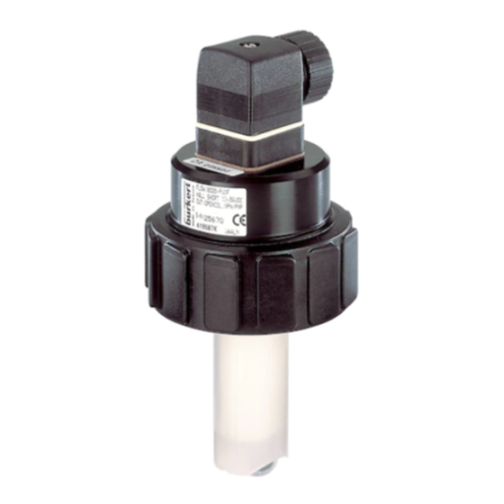
  • Seite 1 Bedienungsanleitung Instruction manual / Notice d’utilisation Durchfluss Sensor Typ 8020 Flow Sensor Type 8020 Capteur de débit type 8020 Inclusiv Typen 8021, 8023, und 1077-3 Included types 8021, 8023, and 1077-3 Inclus types 8021, 8023 et 1077-3...
  • Seite 2: Anschluss - Connection

    L min = 10xD Beispiel - Example - Exemple: LINK Anschluss Durchfluss-Sensor 8020 mit Magnetegelventil Typ 6223 Connection flow sensor 8020 with solenoid control valve type 6223 Connexion capteur de débit 8020 avec électrovanne de régulation type 6223 8020 G - 1 -...
  • Seite 3 Prüfbescheinigung Durchfluss-Sensor Flow sensor test attestation Attestation de test pour capteur de débit Bezeichnung / Designation / Désignation : Flow Sensor Paddle wheel Test Bedingungen / Test conditions / Conditions de test : ° ° Temperatur / Temperature / Température : C / 68 Betriebsdruck / Pressure / Pression : 1,7 bar / 25 psi...
  • Seite 4 DURCHFLUSS SENSOR 8020 8020 BEDIENUNGSANLEITUNG TYP 8020 ..............D-1 INSTRUCTION MANUAL TYPE 8020 ............... E-1 NOTICE D'UTILISATION TYPE 8020 ............... F-1 Beratung und Service ....................A-1 Advice and service ....................A-1 Conseil et service après-vente ................A-1 ***** ©BÜRKERT 1996 TR419607F-607-2-RM Technische Änderungen vorbehalten (Rev 806-IE)
  • Seite 5: Inhaltsverzeichnis

    Allgemeine Hinweise zum elektrischen Anschluss ......... D-10 Elektrischer Anschluss 8020 Standard ............D-11 Anschluss eines 8020 Standard mit Hall Sensor an eine SPS ...... D-12 Elektrischer Anschluss 8020 mit einstellbarem Pulsausgang ......D-13 Elektrischer Anschluss 8020 mit 4...20 mA Ausgang ........D-13 INBETRIEBNAHME ..................
  • Seite 6: Einführung

    Vollständigkeit und Transportschäden. Zur wenn besondere Vorsicht Standardlieferung gehören: geboten ist, um eine einwandfreie Installation, Funktion und Betriebssicherheit -1 Durchfluss-Sensor Typ 8020 des Gerätes zu gewährleisten. -1 Bedienungsanleitung Typ 8020 -1 Bedienungsanleitung Fitting Typ S020/1500/1501 1.4 Elektromagnetische Verträglichkeit Um sicherzustellen, das Sie das richtige Hiermit wird bestätigt, das dieses Produkt...
  • Seite 7: Beschreibung

    8023 8020 8020 8020 45 8020 mit Impulsteiler Typ 8021 123 Durchfluss-Sensor Typ 8020 6 8020 mit 4-20 mA Transmitter Typ 8023 oder 4-20 mA Transmitter Typ 8023 und Bedieneinheit Typ 1077-3 DURCHFLUSS-SENSOR 8020 STANDARD TYPEN Speisung O-Ringe Sensor Anschluss Ident.
  • Seite 8: Aufbau Und Messprinzip

    Das Ausgangsignal steht an einenem angeschlossen werden. 4-poligen Stecker nach DIN 43650 zur Verfügung. 2 Der Durchfluss-Sensor Typ 8020 mit Hall Sensor ist für die Verbindung mit allen Open In den Ausführungen mit 4...20 mA Collector, NPN oder PNP Frequenz Stromausgang und einstellbarem Puls- Eingang Systeme vorbereitet und benötigt...
  • Seite 9: Abmessungen

    DURCHFLUSS SENSOR 8020 2 BESCHREIBUNG 2.3 Abmessungen Typ 8020 Standard 1 2 3 Typ 8020 mit 4...20 mA Ausgang 4 oder einstellbarem Pulsausgang 5 Typ 8020 mit 4...20 mA Ausgang 4 und Bedieneinheit 6 D-6- 8020...
  • Seite 10: Technische Daten

    Transistor NPN/PNP Open Collector, max. 100 mA Frequenz: 0...300 Hz Kablellänge max.: 50 m (abgeschirmtes Kabel max. 1,5 mm Spezifische Daten 8020 mit Hall Sensor "low power" 3 Fitting PVC 50 °C (122 °F); Mediumstemperatur PP; PVDF; Messing; stainless-steel 80 °C (176 °F) Messbereich 0,3 bis 10 m/s (1.0 bis 32.8 ft/s) ab 3 l/min (DN15)
  • Seite 11 DURCHFLUSS SENSOR 8020 2 BESCHREIBUNG Spezifische Daten 8020 mit 4...20 mA Ausgang 4 Verbundener Durchfluss Sensor Ausführung mit Spule oder Hall low power Durchfluss Transmitter 8023 (ref 130428V) Spannungversorgung 12...24 VDC Ausgangssignal 4...20 mA Bürde max. 500Ω bei 12 V; max. 1000Ω bei 24 V ≤...
  • Seite 12: Installation

    Schieber usw.) ist zu vermeiden. die Führungsnut 5 einrasten lassen. Die Mindestein- 10xD und Auslaufstrecken 3. Sensor 8020 1 in den Fitting vorsichtig 3xD nach DIN müssen eingehalten werden. einschieben, bei korrektem Einbau darf Für weiteren Auskunfte, beziehen Sie sich sich der Sensor nicht drehen lassen.
  • Seite 13: Allgemeine Hinweise Zum Elektrischen Anschluss

    2. Das Innenteil 3 aus dem Aussenteil 4 herausnehmen. 3. Gemäss nebenstehender Anschlussbelegung beschalten. Der Durchfluss Sensor 8020 mit Spule kann 4. Beim Zusammenbau kann das Innenteil beliebig in 90 °- Schritten in das Aussenteil eingesetzt werden. an einen Transmitter 8025 angeschlossen werden (siehe Fig.
  • Seite 14: Elektrischer Anschluss 8020 Mit Einstellbarem Pulsausgang

    4: L+(12...30 VDC) Fig. 3.9 Elektrischer Anschluss Typ 8021 3.7 Elektrischer Anschluss 8020 mit 4...20 mA Ausgang 5 (Typ 8023) Zentralschraube lösen und Deckel abnehmen. Das Kabel durch die PG 9 Verschraubung führen und gemäss folgender Anschlussbelegung beschalten (Fig. 3.10 ): 1: L+(12...24 VDC)
  • Seite 15: Inbetriebnahme

    DURCHFLUSS SENSOR 8020 4 INBETRIEBNAHME 4.1 Inbetriebnahme 8020 Standard 4.1.1 Überprüfung der Fitting-Nennweite Beispiel: Fitting DN 25 Rohrwerkstoff PVC Für die geforderte Durchflussmenge kann Frequenz: 108 Hz die optimale Nennweite bei der idealen Durchflussgeschwindigkeit in [m/s] oder Für das Beispiel gilt: [ft/s] mit dem Nomogramm (siehe Anhang) K = 56,59 Puls/l (Fig.
  • Seite 16: Inbetriebnahme 8020 Mit Einstellbarem Pulsausgang

    DURCHFLUSS SENSOR 8020 4 INBETRIEBNAHME 4.2 Inbetriebnahme 8020 mit einstellbarem Pulsausgang Die Bedienung des Impulsteilers erfordert die Eingabe des K-Faktors und eines Multiplikators D. Diese Grössen werden durch Kodierräder und Steckstifte programmiert (siehe Fig. 4.1). Um zur Platine zu gelangen, Zentralschraube lösen und Deckel abnehmen.
  • Seite 17: Programmierung Des Multiplikators D

    100 1000 10000 (Liter/Impuls) Der Impulsteiler erzeugt ein Impuls alle KxD Impulse vom 8020, das heisst, bei jedem Durchgang von Dx1Liter. Im Falle des voherigen Beispiels 1 (K=56,59 puls/l), mit einem Multiplikator D=1, entspricht es einem Impuls alle 56,59 Impulse vom 8020, das heisst ein Impuls pro Liter.
  • Seite 18: Inbetriebnahme 8020 Mit 4

    DURCHFLUSS SENSOR 8020 4 INBETRIEBNAHME 4.3 Inbetriebnahme 8020 mit 4...20 mA Ausgang Betrieb ohne Bedieneinheit Typ 1077-3 Beim Betrieb ohne Bedieneinheit Typ 1077-3 misst das Gerät den aktuellen Durchfluss und gibt am Ausgang das zugehörige Normsignal 4...20 mA aus. Die einstellbaren Werte (K-Faktor, 4...20 mA Messbereich) können nur mittels der Bedieneinheit verändert werden.
  • Seite 19: Standardmodus

    4.3.3 Programmiermodus (siehe Fig. 4.4) Wird die ">" Taste ca. 2 Sek. lang gedrückt, so schaltet sich das Gerät in den Programmiermodus (Achtung: ist keine Frequenz (8020) angeschlossen, so muss die ">" Taste mindestens 8 Sek. lang gedrückt werden). Nacheinander können jetzt K-Faktor, Anfangs- und Endwert eingestellt werden.
  • Seite 20 DURCHFLUSS SENSOR 8020 4 INBETRIEBNAHME Der K-Faktor (Fig. 4.4 und Fig. 4.1) Der K-Faktor dient zur Einstellung der vom Schaufelrad erzeugten Impulse auf die Elektronik. Der K-Faktor gibt an, wieviele Impulse das Schaufelrad pro durchgeflossenem Volumen abgibt. Die Volumeneinheit für den Durchfluss wird durch den K-Faktor bestimmt und muss daher nicht extra angegeben werden.
  • Seite 21 DURCHFLUSS SENSOR 8020 4 INBETRIEBNAHME 120.00 46.60 2 sec. Standardmodus Einstellen des Einstellen des Multiplikators Vorkommawertes für den K-Faktor des K-Faktors Einstellen des Einstellen des Einstellen der Vorkommawertes Nachkommawertes Zeiteinheit des Anfangswertes des K-Faktors Einstellen des Einstellen des Einstellen des...
  • Seite 22: Wartung

    DURCHFLUSS SENSOR 8020 5 WARTUNG 5.1 Ersatzteil-Stückliste Position Bezeichnung Bestellnummer Dichtungssatz in FPM 418213S Dichtungssatz in EPDM 418214T Bedienungsanleitung Type 8020 419607F Bedienungsanleitung Fitting S020/1500/1501 429633S 5.2 Hinweis Störung Bei korrektem Einbau sind die Geräte wartungsfrei. Sollten trotzdem im Betrieb Verunreinigungen oder Verstopfungen vorkommen, kann das Gerät (Messrad, Lager)
  • Seite 23: Anhang

    DURCHFLUSS SENSOR 8020 ANHANG Durchfluss-Diagramm (l/min, DN in mm und m/s) m 3 /h l/min 5000 1000 0.05 Durchflussgeschwindigkeit Auswahlbeispiel: Vorgabe: Nominaler Durchfluss: Ermittlung mit idealer Durchflussgeschwindigkeit: 2...3 m/s Aus dem Diagramm resultiert die erforderliche Nennweite von DN 40. D-22-...
  • Seite 24: Durchfluss-Diagramm (Us-Gallon/Min, Dn In Inch Und Ft/S)

    DURCHFLUSS SENSOR 8020 ANHANG Durchfluss-Diagramm (gpm, DN in inch und fps) 5000 2000 1000 Durchflussgeschwindigkeit Auswahlbeispiel: Vorgabe: Nominaler Durchfluss: 50 gpm Ermittlung mit idealer Durchflussgeschwindigkeit: 8 fps Aus dem Diagramm resultiert die erforderliche Nennweite von 1 1/2" 8020 D-23-...
  • Seite 25: Anschlussmöglichkeiten Durchfluss Sensor 8020 Mit 4

    DURCHFLUSS SENSOR 8020 ANHANG Anschlussmöglichkeiten Durchfluss Sensor 8020 mit 4...20 mA Ausgang Anschluss an Spannungsversorgung und Auswertungsgeräte mit 4...20 mA Eingang (max. Bürde beachten). 8023 Spannungs- versorgung +24 VDC 120.00 Getrennte Regler Schreiber Anzeige Anschluss an SPS (Versorgung durch SPS). Der Anschluss erfolgt unabhängig von SPS-Ausführung.
  • Seite 26 Trouble-shooting ....................E-20 APPENDIX ...................... E-21 Flow Chart (l/min, DN in mm and m/s) ............E-21 Flow Chart (US-gallon/min, DN in inch and Ft/s) ..........E-22 Connection examples of flow sensor type 8020 with 4...20 mA output ..E-23 8020 E-1-...
  • Seite 27: Introduction

    The standard function and use of the product. delivery must include: -1 Flow Sensor type 8020 1.4 Electromagnetic Compatibility -1 Operating Instruction Manual 8020 -1 Operating Instruction Manual This confirms that this product meets the...
  • Seite 28: Specification

    8020 8020 45 8020 with pulse divider type 8021 123 Flow sensor type 8020 6 8020 with 4-20 mA transmitter type 8023 or 4-20 mA transmitter type 8023 and programming module type 1077-3 FLOW SENSOR 8020 STANDARD TYPES Power Supply Gasket...
  • Seite 29: Design And Measuring Principle

    FLOW SENSOR TYPE 8020 2 SPECIFICATION 2.2 Design and Measuring Principle Design 1 The flow sensor 8020 with coil requires The flow sensor consists of a paddle wheel no external power supply . This flow sensor with ceramic bearings. The ceramic rotating...
  • Seite 30: Dimensions

    FLOW SENSOR TYPE 8020 2 SPECIFICATION 2.3 Dimensions Type 8020 standard 1 2 3 Type 8020 with 4...20 mA or adjustable frequency output 4 5 Type 8020 with 4...20 mA output 5 including programming unit type 1077-3 6 8020 E-5-...
  • Seite 31: Technical Data

    Frequency: 0...300 Hz Cable length max.: 50 m (shielded cable section max. 1,5 mm Specific Data type 8020 with Hall sensor "low power" 3 Fitting PVC 50 °C (122 °F); Fluid temperature PP; PVDF; brass; stainless-steel 80 °C (176 °F) Measuring range 0.3 to 10 m/s (1.0 to 32.8 ft/s)
  • Seite 32 FLOW SENSOR TYPE 8020 2 SPECIFICATION Specific Data sensor type 8020 withtype 8023 4 4-20 mA output Associated flow sensor Hall sensor "Low Power" 3 or coil 1 Flow transmitter Type 8023 (ref: 30428 V) Power supply 12...24 VDC Output signal 4...20 mA...
  • Seite 33: Installation

    3.2 Installation The pipe must be completely filled with the The flow sensor 8020 can be easily installed fluid, i.e. air bubbles must not be present. in pipes using our specially designed fitting The device must be protected from constant system.
  • Seite 34: Installation

    3. Connect according to pin assignment on next page. 4. For reassembly, the internal part may be inserted into the The sensor 8020 with coil can be connected external part in 90 °-step intervals as required. to a flowindicator/transmitter/controler type 8025 /SE34 (see fig.
  • Seite 35 8020 (*) Link not necessary for 8020 with coil Fig. 3.5 Flow indicator SE34 separate 3.4.4 Wiring of 8020 with Hall sensor "low power" and with coil to a transmitter 8025 8020 8025 (*) Link not necessary for 8020 with coil Fig.
  • Seite 36 Depending on the PLC version, use either the PNP or NPN version of the pulse output (see Fig. 3.8). (1) L+ (2) Pulse output Hall (3) L- (1) L+ y Pulse output Hall (3) L- Fig. 3.8 Wiring diagram of flow sensor 8020 with Hall sensor 2 to a PLC 8020 E-11-...
  • Seite 37: Electrical Wiring 8020 With Adjustable Pulse Output

    3 INSTALLATION FLOW SENSOR TYPE 8020 3.6 Electrical wiring 8020 with adjustable pulse output 4 Unscrew central screw and remove the cover. Pull cable through PG 9 and wire according to following pin assignment. The connection to a PLC or any other device with frequency...
  • Seite 38: Commissioning

    FLOW SENSOR TYPE 8020 4 COMMISSIONING 4.2 Commissioning 8020 standard 4.1.2 Flow rate determination 4.1.1 Examination of fitting orifice The sensor measures the flow volume via The size, as well as the ideal flow rate in the frequency, which is proportional to the [m/s] or [ft/s] to determine the flow volume flow, generated by the paddle wheel.
  • Seite 39: Commissioning 8020 With Adjustable Pulse Output

    FLOW SENSOR TYPE 8020 4 COMMISSIONING 4.2 Commissioning 8020 with adjustable pulse output type 8021 The programming of the pulse divider requires the entry of a K-factor and a multiplier D. These parameters are programmed through rotary switches and jumpers (see Fig. 4.1).
  • Seite 40 In case of previous example 1 (K=56,59 puls/l), with a coefficient D=1, it corresponds to a pulse all 46,6 pulses from 8020. that is to say one pulse per litre. If in the same case D=10. it corresponds to one pulse each 10 litres.
  • Seite 41: Commissioning 8020 With 4

    4 COMMISSIONING FLOW SENSOR TYPE 8020 4.3 Commissioning 8020 with 4...20 mA output(type 8023) 5 Operation without type 1077-3 control unit If used without the type 1077-3 control unit, the device measures the current flow rate and outputs the associated 4...20 mA standard signal. The adjustable values (fitting factor, 4...20 mA measuring range) can only be changed by using the control unit.
  • Seite 42: Standard Mode

    Pressing the ">" key for approx. 2 secs will switch the device into programming mode (warning : if no sensor (8020) is connected, the ">" key must be pressed for at least 8 secs). The K-factor of the fitting, the lower and upper range values can now be set. Each item is set individually in the sequence described in the following chapter.
  • Seite 43 FLOW SENSOR TYPE 8020 4 COMMISSIONING Fitting Factor-K (see Fig. 4.4 ) The fitting factor (K) adjusts the pulses generated by the paddle wheel to the electronic system. The fitting factor indicates how many pulses the paddle wheel emits per volume flow.
  • Seite 44 FLOW SENSOR TYPE 8020 4 COMMISSIONING Flow transmitter type 8023 programming the Fitting Factor-K 120.00 46.60 2 sec. Standard mode Setting the fitting Setting the pre- factor multiplier decimal point value for the fitting factor Setting the pre- Setting the post-...
  • Seite 45: Maintenance

    FLOW SENSOR TYPE 8020 5 MAINTENANCE 5.1 Spare Parts List ° Position Désignation Order N FPM Seal kit 418213S EPDM Seal kit 418214T Connector DIN43650 type 1502 415435E Instruction manual type 8020 419607F Instruction manual fitting type S020/1500/1501 429633S 5.2 Servicing In correct installation conditions, the flow sensors are maintenance-free.
  • Seite 46: Appendix

    FLOW SENSOR TYPE 8020 APPENDIX Flow Chart (l/min, DN in mm and m/s) m 3 /h l/min 5000 1000 0.05 Flow velocity Selection Example: Specifications: Nominal flow: Determination with ideal flow velocity: 2...3 m/s With these specifications, the required orifice, as defined by the flow chart is DN 40.
  • Seite 47: Flow Chart (Gpm, Dn In Inch And Fps)

    FLOW SENSOR TYPE 8020 APPENDIX Flow Chart (gpm, DN in inch and fps) 5000 2000 1000 Flow velocity Selection Example: Specifications: Nominal flow: 50 gpm Determination with ideal flow velocity: 8 fps With these specifications, the required orifice, as defined by the flow chart is 1 1/2"...
  • Seite 48: Connection Examples Of Flow Sensor Type 8020 With 4

    FLOW SENSOR TYPE 8020 APPENDIX Connections examples of flow sensor type 8020 with 4...20 mA output Connection to voltage supply and measuring equipment with 4...20 mA input (observe max. load impedance) 8023 Voltage supply +24 VDC 120.00 Plotter Separate Controller display Connection to PLC (supply from the PLC).
  • Seite 49 Entretien ......................F-20 ANNEXE ......................F-21 Abaque débit/vitesse/diamètre (l/min, DN en mm et m/s) ....... F-21 Abaque débit/vitesse/diamètre (US-gallon/min, DN en pouce et Ft/s) .... F-22 Exemple de connexion du capteur de débit 8020 avec sortie 4...20 mA ..F-23 F-1- 8020...
  • Seite 50: Capteur De Debit Type 8020

    CAPTEUR DE DEBIT TYPE 8020 Cher client, nous vous félicitons pour l'achat de notre 1.3 Consignes de sécurité capteur de débit 8020. Pour utiliser pleinement et en toute confiance les Bürkert commercialise une large gamme de fonctions de cet instrument, capteurs de débit.
  • Seite 51: Description

    ° CAPTEUR DE DEBIT 8020 AVEC DIVISEUR D'IMPULSIONS Joint Capteur Connection 4 8020 avec capteur à effet Hall + Type 8021 12-30 VCC Hall court DIN 43650 PG9 419595K 4 8020 avec capteur à effet Hall + Type 8021 12-30 VCC...
  • Seite 52: Construction Et Principe De Mesure

    2.2 Construction et principe de mesure Construction Le capteur de débit se compose d'une ailette 1 Le capteur de débit 8020 à bobine ne pourvue de paliers en céramique. L'axe de nécessite pas d'alimentation externe. Il peut rotation, également en céramique, est fixé...
  • Seite 53: Dimensions

    2 DESCRIPTION CAPTEUR DE DEBIT TYPE 8020 2.3 Dimensions Type 8020 standard 1 2 3 Type 8020 avec sortie 4...20 mA ou sortie impulsion configurable 4 5 Type 8020 avec sortie 4...20 mA 5 et unité de programmation type 1077-3 6...
  • Seite 54: Caractéristiques Techniques

    0...200 Hz Longueur de câble max.: 50 m (câble blindé section max. 1,5 mm Caractéristiques spécifiques au 8020 avec capteur à effet Hall "low power" 3 Raccord PVC 50 °C (122 °F); Température du fluide PP,PVDF,inox,laiton 80 °C (176 °F) Plage de mesure 0,3 à...
  • Seite 55 2 DESCRIPTION CAPTEUR DE DEBIT TYPE 8020 Caractéristiques spécifiques du capteur 8020 avec sortie 4...20 mA type 8023 4 Capteur de débit associé Capteur à effet Hall "Low Power" ou bobine Transmetteur de débit 8023 (réf 130428 V) Tension d'alimentation 12...24 VCC...
  • Seite 56: Installation

    Conditions d'installation Fig. 3.2 Montage capteur de débit 8020 3.2 Montage La conduite doit être remplie par le fluide, absence totale de bulles d'air. Le capteur de débit 8020 s'installe dans les L'appareil doit être protégé conduites à l'aide de raccords spéciaux.Le rayonnements thermiques et des effets capteur de débit peut être installé...
  • Seite 57: Installation

    Dans les conditions normales d'utilisation, 8020 à effet Hall 2 50 m un câble simple à section de 0,75 mm 8020 à effet Hall "Low Power" 3 50 m suffisant pour la transmission du signal de mesure. En cas de doute, utiliser cependant toujours (*) : Avec câble blindé.
  • Seite 58 (*) Liaison superflue pour capteur 8020 à bobine Fig. 3.5 Indicateur de débit SE34 distant 3.4.2 Raccordement à un transmetteur/contrôleur 8025 d'un capteur de débit 8020 à effet Hall "Low Power" ou à bobine 8020 8025 (*) Liaison inutile pour 8020 avec bobine Fig.
  • Seite 59 PNP (voir fig 3.8 ). La longueur maximale de câble est de 50 m (cf § 3.3.1) (1) L+ (2) Sortie impulsion Hall Automate (3) L- (1) L+ y Sortie impulsion Automate Hall (3) L- Fig. 3.8 Schéma de connexion pour type 8020 avec capteur à effet Hall F-11- 8020...
  • Seite 60: Raccordement Électrique 8020 Avec Sortie Impulsions Configurable

    3 INSTALLATION CAPTEUR DE DEBIT TYPE 8020 3.6 Raccordement électrique 8020 avec sortie impulsion configurable 4 Dévisser la vis centrale et ôter le couvercle. Passer les câbles à travers le presse-étoupe du module 8021et relier sur le bornier suivant les indications ci-dessous:...
  • Seite 61: Mise En Service

    4 MISE EN SERVICE CAPTEUR DE DEBIT TYPE 8020 4.1 Mise en service 8020 standard Exemple: raccord DN 25 4.1.1 Vérification du DN du raccord matériau du raccord: PVC fréquence mesurée: 108 Hz Avec un débit donné, le diamètre du raccord pour une vitesse de fluide idéale, peut être...
  • Seite 62: Mise En Service 8020 Avec Sortie Impulsions Configurable

    4 MISE EN SERVICE CAPTEUR DE DEBIT TYPE 8020 4.2 Mise en service 8020 avec sortie impulsions configurable (module 8021) La configuration du diviseur d'impulsions nécessite la saisie du coefficient spécifique du raccord (facteur K) et d'un coefficient multiplicateur D. Ces grandeurs sont programmées à...
  • Seite 63: Programmation Du Coefficient Multiplicateur D

    Le diviseur d'impulsions génère une impulsion toutes les K x D impulsions provenant du capteurde débit 8020, c'est à dire à chaque passage de Dx1 litre. Dans le cas de l'exemple 1 précédent (K=56,59 puls/l), avec un coefficient D=1, cela correspond à une impulsion tous les 56,59 impulsions du capteur de débit 8020 , c'est à...
  • Seite 64: Mise En Service 8020 Avec Sortie 4

    4 MISE EN SERVICE CAPTEUR DE DEBIT TYPE 8020 4.3 Mise en service 8020 avec sortie 4...20 mA (module 8023) Utilisation sans unité de commande de type 1077-3 Le transmetteur 8023 génère en sortie un signal normalisé 4 ... 20 mA proportionnel au débit en fonction des paramètres saisis.
  • Seite 65: Mode Standard

    4 MISE EN SERVICE CAPTEUR DE DEBIT TYPE 8020 4.3 Mise en service 8020 avec sortie 4...20 m A (module 8023) 4.3.2 Mode standard Après l'application de la tension d'alimentation, tous les segments de l'unité de commande s'allument pendant environ 2 secondes (test d'affichage). Puis le débit actuel s'affiche et le signal normalisé...
  • Seite 66 CAPTEUR DE DEBIT TYPE 8020 4 MISE EN SERVICE 4.3 Mise en service 8020 avec sortie 4...20 m A (module 8023) 4.3.3 Mode programmation (voir Fig. 4.4) Facteur K (Fig. 4.4) Le facteur K indique le nombre d'impulsions que l'ailette en rotation transmet par volume écoulé.
  • Seite 67 4 MISE EN SERVICE CAPTEUR DE DEBIT TYPE 8020 Programmation du module transmetteur type 8023 120.00 46.60 2 sec. Mode standard Réglage du Réglage de la multiplicateur du valeur entière du facteur K facteur K Réglage de la Réglage de la Réglage de...
  • Seite 68: Maintenance

    5 MAINTENANCE CAPTEUR DE DEBIT TYPE 8020 5.1 Liste des pièces de rechange Position Désignation Référence Lot de joints toriques FPM 418213S Lot de joints toriques EPDM 418214T Manuel d'utilisation type 8020 419607F Manuel d'utilisation fitting type S020/1500/1501 429633S 5.2 Entretien Si l'installation et les conditions d'utilisation sont correctes, le capteur de débit ne nécessite...
  • Seite 69: Annexe

    ANNEXE CAPTEUR DE DEBIT TYPE 8020 Abaque débit/vitesse/diamètre (l/min, DN en mm et m/s) m 3 /h l/min 5000 1000 0.05 Vitesse du fluide Exemple: Données: Débit: 10m Vitesse optimale du fluide: 2...3 m/s Selon l'abaque un raccord DN 40 est le mieux approprié.
  • Seite 70: Abaque Débit/Vitesse/Diamètre (Us-Gallon/Min, Dn En Pouce Et Ft/S)

    ANNEXE CAPTEUR DE DEBIT TYPE 8020 Abaque débit/vitesse/diamètre (US-gallon/min, DN en inch et ft/s) 5000 2000 1000 Vitesse du fluide Exemple: Données: Débit: 50 gpm Vitesse optimale du fluide: 8 fps Selon l'abaque un raccord 1 1/2" est le mieux approprié.
  • Seite 71: Exemple De Connexion Du Capteur De Débit 8020 Avec Sortie 4

    ANNEXE CAPTEUR DE DEBIT TYPE 8020 Exemples de connexion du capteur de débit 8020 avec sortie 4...20 m A (module 8023) Connexion avec alimentation et appareils interpretantle signal 4 ... 20 mA (respecter la charge maximale) 8023 Alimentation +24 VDC 120.00...
  • Seite 72: Beratung Und Service Advice And Service

    Fax (07 11) 45 11 066 Fax (0359) 523 65 51 Fax (030) 67 991 341 INTERNATIONAL Australia Denmark Indonesia Burkert Fluid Control Systems Bürkert-Contromatic A/S, P.T. Fulkosindo Unit 1 No.2, Welder Road, Hørkær 24, JLKH Hasyim Ashari No. AUS-Seven Hills NSW 2147...
  • Seite 73 CONSEIL ET SERVICE APRES-VENTE Netherlands Singapore Taiwan Bürkert Contromatic BV, Burkert Contromatic Singapore Bürkert Contromatic Taiwan Ltd., Computerweg 9, Pte.Ltd., 3F N° 475 Kuang-Fu South Road No.11 Playfair Road, R.O.C-Taipei City NL-3606 AV Maarssen, Tel. (034) 65 95 311, Singapore 367986, Tel.

Inhaltsverzeichnis