bürkert 8030 HT Bedienungsanleitung
Mit flügelrad für hohe temperaturen

Verwandte Anleitungen für bürkert 8030 HT


Inhaltszusammenfassung für bürkert 8030 HT
- Seite 20 Flow Sensor 8030 ht aNNex...
- Seite 21 8030 ht Bedienungsanleitung © Bürkert 2003-2011 Technische Änderung vorbehalten...
- Seite 22 8030 ht inhaltsverzeichnis 1 ALLGEMEINE SICHERHEITSHINWEISE � �������������������������������������������������������������������������������������������������������4 1.1 Bestimmungsgemäße Verwendung ...........................4 1.2 Gefahren bei der Installation und Inbetriebnahme ....................5 1.3 Normenbezüge ....................................5 2 BESCHREIBUNG �������������������������������������������������������������������������������������������������������������������������������������������������������6 2.1 Aufbau und Messprinzip ................................6 2.2 Ausführungen des Elektronikmoduls SE30 HT .......................7 2.3 Abmessungen (mm) ..................................7 3 TECHNISCHE DATEN � ���������������������������������������������������������������������������������������������������������������������������������������������8 4 INSTALLATION ���������������������������������������������������������������������������������������������������������������������������������������������������������12...
- Seite 23 4.3.1 Anschlussstecker EN 175301-803 (Typ 2508, geliefert) ............13 4.3.2 Steckerverbindung des Frequenzausgangs: Puls-Version (NPN- und PNP ....14 Transistor-Ausgänge) ..............................14 4.3.3 Steckerverbindung des Frequenzausgangs: Sinus-Version (Spule-Ausgang) .....15 5 ANHANG � ���������������������������������������������������������������������������������������������������������������������������������������������������������������������16 5.1 Beschreibung des Typenschilds des SE30 HT .....................16 5.2 Durchfluss-DN-Flüssigkeitsgeschwindigkeit-Diagramme ................17 5.4 Anschluss-Beispiel ..................................19 8030 ht...
-
Seite 24: Allgemeine Sicherheitshinweise
Kennzeichung der sicherheitshinweise erfolgt durch das nebenstehende symbol. 1.1 Bestimmungsgemäße Verwendung Der Sensor 8030 HT darf nur zur Durchflussmessung in teilchenfreien neutralen oder leicht aggressiven Flüssigkeiten eingesetzt werden. Für Schäden aus unsachgemässem oder nicht bestimmungsgemässem Gebrauch haftet der Hersteller nicht. An dem Gerät dürfen keine Umbauten oder Veränderungen vorgenommen werden. -
Seite 25: Gefahren Bei Der Installation Und Inbetriebnahme
Ultraviolettbestrahlung und, bei einer Außenanwendung, von den Wetterbedingungen. dem verwendeten prozess entsprechend müssen geeignete Vor- sichtsmaßnahmen getroffen werden, bevor der sensor abgebaut wird. 1.3 normenbezüge EMV: EN 50081-1, 61000-6-2 Sicherheit: EN 61010-1 Vibration: EN 60068-2-6 Stoß: EN 60068-2-27 8030 ht... -
Seite 26: Beschreibung
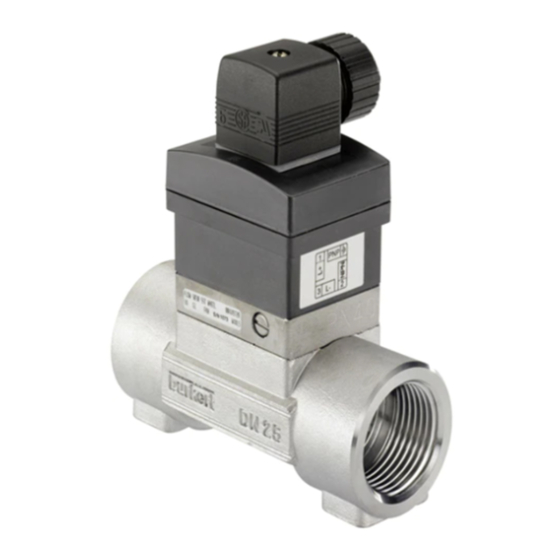
BeschreiBung durchfluss-sensor 8030 ht 2.1 aufbau und messprinzip Der Durchfluss-Sensor 8030 HT besteht aus einem Elektronikmodul SE30 HT und einem Fitting S030 HT mit integriertem metallischem SE30 HT Flügelrad. Das durch die strömende Flüssigkeit in Bewegung gesetzte Flügelrad erzeugt eine dem Durchfluss Q proportionale Messfrequenz f. -
Seite 27: Ausführungen Des Elektronikmoduls Se30 Ht
2.2 ausführungen des elektronikmoduls se30 ht Versorgungsspannung Frequenzausgang Elektrischer Anschluss Bestell-Nr� 12-36 VDC Puls: 1 NPN-Transistor + 1 PNP-Transistor EN 175301-803 Stecker 449694 Keine Sinusförmig: 1 Spule EN 175301-803 Stecker 449693 2.3 abmessungen (mm) EN 175301-803 S030 [mm] 95.5 95.5 100.5 105.5 8030 ht... -
Seite 28: Technische Daten
8030 ht allgemeine daten Rohrleitungsdurchmesser DN6 bis DN50 (DN65 auf Anfrage); Verwenden Sie die Durchfluss-Geschwindigkeits- Diagramme im Anhang, um den geeigneten Rohrleitungsdurchmesser auszuwählen. Flüssigkeits-Temperatur -15 °C bis 125 °C Flüssigkeits-Druck PN40 bei T < 90 °C Flüssigkeit PN25 bei 90 °C <... -
Seite 29: Elektrische Anschlüsse
Dichtung/Achse Fitting S030 HT FKM / Keramik umgebungs-Bedingungen Umgebungstemperatur - Puls-Version: -15 bis +80° C (Betrieb- und Lager) - Sinus-Version: -15 bis +100° C Relative Feuchte < 80%, nicht kondensiert Schutzart des Gehäuses IP 65 mit eingestecktem und festgeschraubtem Stecker 8030 ht... - Seite 30 8030 ht Messgenauigkeit ohne und mit Kalibrierung vor Ort (z.B. Teach-in eines Transmitters 8025) max. Fehl-% Mit Kalibrierung vor Ort Ohne Kalibrierung vor Ort, aber mit standard K-Faktor Flüssigkeits- geschwindigkeit in v.E = vom Endwert v.M. = vom Messwert Diese Werte wurden unter folgenden Referenzbedingungen festgelegt: Flüssigkeit = Wasser, Wasser- und Umgebungs-...
- Seite 31 8030 ht...
-
Seite 32: Installation
8030 ht 4.1 allgemeine hinweise Überprüfen Sie immer die chemische Kompatibilität der Sensor- Werkstoffe mit denen das Gerät in Kontakt kommt. Für weitere Auskünfte, steht Ihnen Bürkert zur Verfügung. 4.2 einbau in die rohrleitung Das Elektronik-Modul SE30 HT wird auf ein Fitting S030 HT montiert für den Einbau in die Rohrleitung. -
Seite 33: Elektrischer Anschluss
- Innenteil [2] zurückstecken. - Kabelverschraubung [6] festschrauben. - Flachdichtung [1] zwischen dem Stecker und dem Steck- verbinder des 8030HT einsetzen. - Stecker an 8030HT anschließen. - Schraube [3] festziehen, um die Dichtheit sowie guten elektrischen Kontakt zu vergewissern 8030 ht... -
Seite 34: Steckerverbindung Des Frequenzausgangs: Puls-Version
8030 ht 4.3.2 steckerverbindung des frequenzausgangs: puls-Version (npn- und pnp transistor-ausgänge) Sensor Empfänger Sensor Empfänger Last Ausgang Ausgang Last npn-transistor-ausgang pnp-transistor-ausgang PNP-Transistor-Ausgang npn oder pnp-transistor-anschluss (12-36 VDC) des en 175301-803-steckers NPN-Transistor-Ausgang 0 VDC erden sie die abschirmung! -
Seite 35: Steckerverbindung Des Frequenzausgangs: Sinus-Version (Spule-Ausgang)
4.3.3 steckerverbindung des frequenzausgangs: sinus-Version (spule-ausgang) Sensor Empfänger Last Spule spule-ausgang Nicht belegt Nicht belegt spule-anschluss des en 175301-803-steckers Spule-Ausgang Spule-Ausgang erden sie die abschirmung! 8030 ht... -
Seite 36: Anhang
8030 ht 5.1 Beschreibung des typenschilds des se30 ht FLOW:SE30/8030 COIL 12-36V DC OPEN COLLECTOR PNP/NPN FLUID : 160°C 449694 W46LG 1. Geräte-Typ 2. Betriebsspannung 3. Puls-Ausgang-Kenngrößen 4. Max. Flüssigkeitstemperatur 5. CE-Marke 6. Werkinterne Nummer 7. Bestell-Nummer 8. Sinus-Ausgang-Typ... -
Seite 37: Durchfluss-Dn-Flüssigkeitsgeschwindigkeit-Diagramme
5.2 durchfluss-dn-flüssigkeitsgeschwindigkeit-diagramme Durchfluss 8030 ht... - Seite 38 8030 ht Durchfluss...
-
Seite 39: Anschluss-Beispiel
5.4 anschluss-Beispiel anschluss eines 8030ht, puls-Version (npn* und PNP (*) 8030 HT pnp*-transistor-aus- SOURCE SINK PE PE gänge) an einen trans- Iout L+ L- SENSOR INPUT LOAD CURRENT Supply PULSE 13..30Vdc OUTPUT mitter 8025 universal PULSE INPUT SUPPLY 2.2K COIL... - Seite 40 8030 ht...
-
Seite 57: Abaques Débit-Dn-Vitesse
5.2 abaques débit-dn-vitesse Débit 8030 ht...