
Verwandte Anleitungen für ESX XENIUM XE6440-DSP V2


Inhaltszusammenfassung für ESX XENIUM XE6440-DSP V2
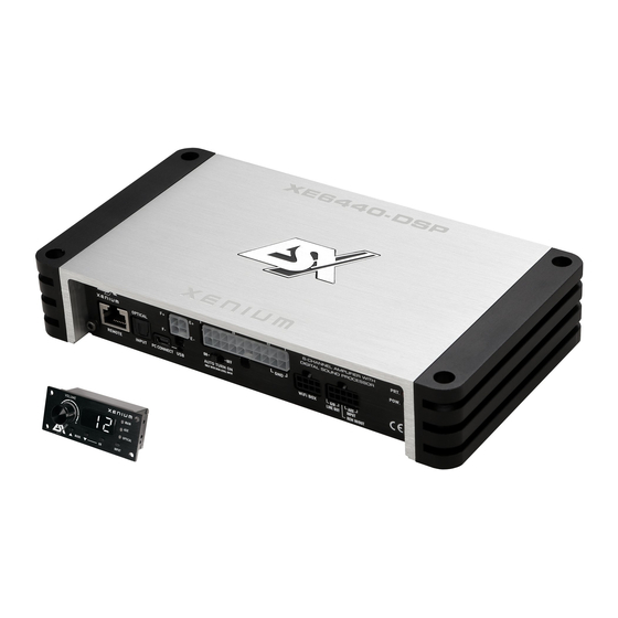
- Seite 1 BENUTZERHANDBUCH BENUTZERHANDBUCH OWNER’S MANUAL OWNER’S MANUAL VERS. 2.0 XE6440-DSP CLASS D 6-CHANNEL AMPLIFIER WITH DSP PROCESSOR...
-
Seite 2: Inhaltsverzeichnis
INHALTSVERZEICHNIS TECHNISCHE DATEN SICHERHEITSHINWEISE INSTALLATIONSHINWEISE Mechanische Installation ........................5 Elektrische Anschlüsse ........................6 FUNKTIONSHINWEISE Funktionen und Bedienelemente .......................8 Installation der DSP-Software ......................10 Bedienoberfläche der Software .......................12 FEHLERBEHEBUNG Aufgrund fortlaufender Weiterentwicklungen ist es möglich, dass die in diesem Benutzerhandbuch enthaltenen Hinweise und Informati- onen nicht vollständig dem Auslieferungszustand des Geräts entsprechen. -
Seite 3: Technische Daten
TECHNISCHE DATEN MODELL XE6440-DSP KANÄLE SCHALTUNGSPRINZIP CLASS D Digital KANAL A/B/C/D AUSGANGSLEISTUNG RMS 13,8 V Watt an 4 / 2 Ohm 4 x 40/60 AUSGANGSLEISTUNG MAX. 13,8 V Watt an 4 / 2 Ohm 4 x 80 /120 KANAL E/F AUSGANGSLEISTUNG RMS 13,8 V Watt an 4 / 2 Ohm 2 x 70/100... -
Seite 4: Sicherheitshinweise
SICHERHEITSHINWEISE BITTE BEACHTEN SIE DIE FOLGENDEN HINWEISE VOR INBETRIEBNAHME! DAS VON IHNEN ERWORBENE GERÄT IST NUR FÜR DEN BETRIEB DAS GERÄT NICHT AN STELLEN EINBAUEN, AN DENEN ES HOHER AN EINEM 12-V-BORDNETZ EINES FAHRZEUGS AUSGELEGT. An- FEUCHTIGKEIT ODER STAUB AUSGESETZT IST. Bauen Sie das Ge- dernfalls besteht Feuergefahr, die Gefahr eines elektrischen Schlages oder rät so ein, dass es vor hoher Feuchtigkeit und Staub geschützt ist. -
Seite 5: Installationshinweise
INSTALLATIONSHINWEISE HINWEIS Bevor Sie mit der Installation des Soundsystems beginnen, trennen Sie unbedingt den Massepol der Fahrzeugbatterie ab, um Kurzschlüsse und Stromschläge zu vermeiden. MECHANISCHE INSTALLATION Achten Sie bei der Installation darauf, dass keine serienmäßig im KFZ vorhandenen Teile wie z.B. Kabel, Bordcomputer, Sicherheitsgur- te, Tank oder ähnliche Teile beschädigt bzw.entfernt werden. -
Seite 6: Elektrische Anschlüsse
INSTALLATIONSHINWEISE ELEKTRISCHE ANSCHLÜSSE ISO-ANSCHLÜSSE ISO-BELEGUNG* VOM FAHRZEUG Lautsprecheranschlüsse B1 Rechts Hinten + B5 Links Front + B2 Rechts Hinten – B6 Links Front – B3 Rechts Front + B7 Links Hinten + B4 Rechts Front – B8 Links Hinten – Systemanschlüsse A1 Geschw.-Signal A5 Antenne/Remote... - Seite 7 INSTALLATIONSHINWEISE VOR DEM ANSCHLIESSEN • Bevor Sie mit der Installation des Soundsystems beginnen, trennen Sie bitte unbedingt den Massepol der Autobatterie ab, um Kurz- schlüsse und Stromschläge zu vermeiden. • Ziehen Sie vorsichtig Ihr Autoradio (Steuergerät) aus dem Radioschacht. • Entfernen Sie die beiden ISO-Anschlüsse (#6) auf der Rückseite des Autoradios (#4).
-
Seite 8: Funktionshinweise
E / F / G / H HIGH LEVEL SPEAKER BAT T. XE4240-DSP FUNKTIONSHINWEISE LINE OUT INPUT OUTPUT +12V 4-CHANNEL AMPLIFIER WITH PRT. DIGITAL SOUND PROCESSOR OPTICAL POW. FUNKTIONEN UND BEDIENELEMENTE DES VERSTÄRKERS AUTO TURN ON REMOTE INPUT PC CONNECT USB ONLY WITH HIGH LEVEL INPUT IN/OUT INPUT... -
Seite 9: Funktionen Und Bedienelemente Der Fernbedienung
AUTO REMOTE INPUT PC CONNECT USB ONLY WI FUNKTIONSHINWEISE FUNKTIONEN UND BEDIENELEMENTE DER FERNBEDIENUNG VOLUME MAIN OPTICAL – OPTICAL MODE INPUT AUTO REMOTE INPUT PC CONNECT USB ONLY WI VOLUME MAIN Mit diesem Regler kann die Gesamtlautstärke des Soundsystems geregelt werden. Wenn Sie den Regler drücken und ca. 3 Sekunden halten kann damit auch der Basspegel von Ausgang LINE OUT (G/H) geregelt werden. -
Seite 10: Installation Der Dsp-Software
Die Installation benötigt ca. 25 MB freien Speicherplatz. Prinzipbedingt sollte dafür ein tragbarer Laptop-Computer verwendet werden. 2. Nachdem Sie die X-CONTROL 2 Software unter http://www.audiodesign.de/esx/dsp heruntergeladen haben, entpacken Sie zu- nächst die heruntergeladene „.rar“-Datei mit einer geeigneten Software wie beispielsweise WinRAR auf Ihrem PC. - Seite 11 FUNKTIONSHINWEISE Klicken Sie auf Click here to test um die Verbindung zum DSP-Gerät zu prüfen Wurde der Test erfolgreich durchgeführt erscheinen 4 Häkchen in den Checkboxen. Drü- cken Sie dann auf „[OK] Click here to start“ um fortzufahren. Sollte eines der Häkchen bei einer Checkbox nicht erscheinen, liegt ein Problem vor wel- ches zu einer Fehlfunktion führen kann.
-
Seite 12: Bedienoberfläche Der Software
FUNKTIONSHINWEISE BEDIENOBERFLÄCHE DER SOFTWARE Hier können Sie unzählige Einstellungen vornehmen und an Ihr Soundsystem anpassen, welche in Echtzeit über den DSP-Gerät sofort hörbar sind. Sobald Sie mit der Konfiguration eines Settings fertig sind, kann dieses auf den einen Speicherplatz im DSP-Gerät übertra- gen werden. - Seite 13 Unter „PRESETS ON THE DEVICE“, können Sie die Speicherplätze (POS1 - POS10) für die einzelnen Settings auf dem DSP- FUNKTIONSHINWEISE Gerät auslesen, löschen oder belegen. Wählen Sie zunächst den Speicherplatz (POS1 - POS10), denn Sie bearbeiten oder auslesen möchten aus. WRITE*: Speichert die augenblicklich eingestellte Einstellungen (Setting) im DSP-Gerät auf dem zuvor ausgewählten Speicherplatz ab.
- Seite 14 FUNKTIONSHINWEISE Im Abschnitt „TIME ALIGNMENT“ finden Sie eine vereinfachte Mög- lichkeit, die Laufzeitkorrektur der einzelnen Kanäle von X-CONTROL 2 berechnen zu lassen, um das Soundsystem und das DSP-Gerät optimal auf die akustische Bühnenmitte auszurichten. Beachten Sie dazu die folgenden Schritte: •...
-
Seite 15: Fehlerbehebung
FEHLERBEHEBUNG STÖRUNGEN / INTERFERENZEN Die Ursache von Interferenzen sind meist immer die verlegten Kabel. Besonders anfällig dafür sind die Strom- und Cinchkabel des Sound Systems. Oftmals werden Interferenzen durch Generatoren (Lichtmaschine) oder andere elektronische Steuergeräte des KFZ (Benzinpumpe, Klimaanlage etc.) verursacht. Die meisten dieser Probleme können durch korrektes und sorgfältiges Verkabeln vermie- den werden. - Seite 16 FEHLERBEHEBUNG Fehler: keine Funktion Ursache: Lösung: 1. Die Stromversorgungskabel sind nicht korrekt angeschlossen. Erneute Überprüfung 2. Die Kabel haben keinen elektrischen und mechanischen Kontakt. Erneute Überprüfung 3. Die Remote-Steuerleitung des Steuergeräts (Autoradio) ist nicht korrekt am Verstärker angeschlossen. Erneute Überprüfung 4.
- Seite 17 FEHLERBEHEBUNG Fehler: kein Ton vom Subwoofer Ursache: Lösung: 1. Die Lautstärke des Subwoofer-Ausgangs (Kanal G/H bzw. SUB OUT) ist an der Fernbedienung zu leise eingestellt. Regler der Fernbedienung drücken und halten, Lautstärke erhöhen wie auf Seite. 7 beschrieben. Fehler: „ERROR“-Meldung bei Verbindung zwischen DSP-Gerät und Computer Ursache: Lösung: 1.
-
Seite 18: Scope Of Delivery
SCOPE OF DELIVERY SPECIFICATIONS SAFETY INSTRUCTIONS INSTALLATION INSTRUCTIONS Mechanical installation ........................21 Electrical interconnection.........................22 FUNCTIONAL INSTRUCTIONS Features and operational controls ....................24 Installation of the DSP software ......................26 User Interface of the software ......................28 TROUBLE SHOOTING Due to the ongoing development of this device, it is possible that the information in this manual is incomplete or is not matching to the delivery status. - Seite 19 SPECIFICATIONS MODEL XE6440-DSP CHANNELS CIRCUIT CLASS D Digital CHANNEL A/B/C/D OUTPUTPOWER RMS 13,8 V Watts @ 4 / 2 Ohms 4 x 40/60 OUTPUTPOWER MAX 13,8 V Watts @ 4 / 2 Ohms 4 x 80 /120 CHANNEL E/F OUTPUTPOWER RMS 13,8 V Watts @ 4 / 2 Ohms 2 x 70/100 Watts @ 4 Ohms bridged...
-
Seite 20: Safety Instructions
SAFETY INSTRUCTIONS PLEASE NOTE THE FOLLOWING ADVICE BEFORE THE FIRST OPERATION! THE PURCHASED DEVICE IS ONLY SUITABLE FOR AN OPERATION DO NOT INSTALL THE DEVICE AT LOCATIONS, WHERE IT WILL BE WITH A 12V ON-BOARD ELECTRICAL SYSTEM OF A VEHICLE. Other- EXPOSED TO HIGH HUMIDITY AND DUST. -
Seite 21: Installation Instructions
INSTALLATION INSTRUCTIONS NOTE Before you start with the installation of the sound system, disconnect necessarily the GROUND connection wire from the battery to avoid any risk of electric shocks and short circuits. MECHANICAL INSTALLATION Avoid any damages on the components of the vehicle like air bags, cables, board computer, seat belts, gas tank or the like. Ensure that the chosen location provides a sufficient air circulation for the processor. -
Seite 22: Electrical Interconnection
INSTALLATION INSTRUCTIONS ELECTRICAL INTERCONNECTION ISO-CONNECTORS ISO-ASSIGNMENT* OF THE VEHICLE Speaker Connections Lautsprecheranschlüsse B1 Right Rear + B5 Left Front + B1 Rechts Hinten + B5 Links Front + B2 Right Rear – B6 Left Front – B2 Rechts Hinten – B6 Links Front –... - Seite 23 INSTALLATION INSTRUCTIONS BEFORE CONNECTING • Before you start with the installation of the sound system, disconnect necessarily the GROUND connection wire from the battery to avoid any risk of electric shocks and short circuits. • Carefully remove your car stereo/head unit from the radio bay. •...
-
Seite 24: Functional Instructions
E / F / G / H HIGH LEVEL SPEAKER BAT T. XE4240-DSP FUNCTIONAL INSTRUCTIONS LINE OUT INPUT OUTPUT +12V 4-CHANNEL AMPLIFIER WITH PRT. DIGITAL SOUND PROCESSOR OPTICAL POW. AMPLIFIER FEATURES AND OPERATIONAL CONTROLS AUTO TURN ON REMOTE INPUT PC CONNECT USB ONLY WITH HIGH LEVEL INPUT IN/OUT INPUT... - Seite 25 FUNCTIONAL INSTRUCTIONS REMOTE FEATURES AND OPERATIONAL CONTROLS VOLUME MAIN – OPTICAL MODE INPUT VOLUME MAIN With this knob the overall volume of the sound system can be controlled. If you press and hold the knob for 3 seconds, the bass level of output SUB OUT (G / H) can also be controlled.
- Seite 26 The installation requires approximately 25 MB of free space. Due to the principle it should be used with a portable laptop computer. 2. After downloading the X-CONTROL 2 software at http://www.audiodesign.de/esx/dsp, unpack the downloaded “.rar” file with a suit- able software such as WinRAR on your PC.
- Seite 27 FUNCTIONAL INSTRUCTIONS Click on Click here to test to check the connection with the DSP device. If the test was performed successfully 4 checkmarks in the check boxes appear. Then press „[OK] Click here to start“ to continue. Should one of the checkmarks not appear, a problem occurred that can lead to a malfunc- tion.
- Seite 28 FUNCTIONAL INSTRUCTIONS USER INTERFACE OF THE SOFTWARE Here you can make countless settings and adapt them to your sound system, which can be heard immediately in real time via the DSP device. As soon as you are finished configuring a setting, it can be transferred to one memory locations in the DSP device. You can store up to 10 different settings and select the remote control at any time during operation.
- Seite 29 FUNCTIONAL INSTRUCTIONS Under „PRESETS ON THE DEVICE“, you can read, delete or assign the memory locations (POS1 - POS10) for the individual set- FUNKTIONSHINWEISE tings on the DSP unit. First select the memory location ((POS1 - POS10), because you want to edit or read out. WRITE*: Saves the currently created setting in the DSP device to the previously selected memory location.
- Seite 30 FUNCTIONAL INSTRUCTIONS In the „TIME ALIGNMENT“ section you have the possibility to calculate the run-time correction of the individual channels by X-CONTROL 2, to optimally align the sound system and the DSP device to the acoustic stage center. To do this, follow these steps: •...
- Seite 31 TROUBLE SHOOTING ELECTRICAL INTERFERENCES The reason for interferences are mostly the routed cables and wires. Especially the power and audio cables (RCA) of your sound system are vulnerable. Often these interferences are caused by electric generators or other electrical units (fuel pump, AC etc.) of the car. The most of these problems can be prevented by a correct and careful wiring.
- Seite 32 TROUBLE SHOOTING Malfunction: no function Reason: Remedy: 1. The power supply connection of the device is not correct Recheck 2. The cables have no mechanical or electrical contact Recheck 3. The remote turn-on connection from the head unit to the amplifier is not correct Recheck 4.
- Seite 33 TROUBLE SHOOTING Malfunction: no subwoofer sound Reason: Remedy: 1. The volume of the subwoofer output (channel G / H and SUB OUT) is set too low on the remote control. Press the remote controller and hold. Turn up the volume. (Refer to page 25).
- Seite 34 NOTES REMOTE...
- Seite 35 NOTES E / F / G / H HIGH LEVEL SPEAKER BAT T. XE4240-DSP LINE OUT INPUT OUTPUT +12V 4-CHANNEL AMPLIFIER WITH PRT. DIGITAL SOUND PROCESSOR OPTICAL POW. AUTO TURN ON REMOTE INPUT PC CONNECT USB IN/OUT INPUT ONLY WITH HIGH LEVEL INPUT HIGH LEVEL SPEAKER BAT T.
- Seite 36 Audio Design GmbH Am Breilingsweg 3 · D-76709 Kronau/Germany Tel. +49 7253 - 9465-0 · Fax +49 7253 - 946510 www.audiodesign.de © Audio Design GmbH, all rights reserved. Technical changes, errors and mistakes reserved.