Inhaltsverzeichnis
Werbung
Verfügbare Sprachen
Verfügbare Sprachen
Quicklinks
- 1 Technische Daten
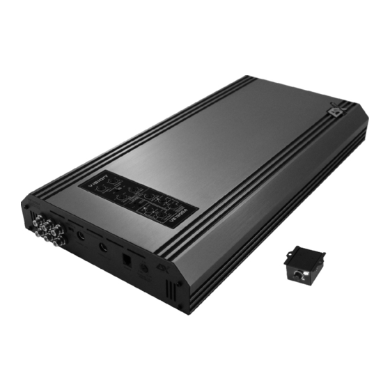
- 2 2-Kanal Verstärker Ve1000.2 / Ve1800
- 3 Funktionsbeschreibung
- 4 Anschlussbeispiele - 1-Kanal-Modus: 1 Subwoofer / Mono Gebrückt
- 5 4-Kanal Verstärker Ve800.4 / Ve1200
- 6 Anschlussbeispiele - 2-Kanal-Modus: 2 Subwoofer / Mono Gebrückt
- 7 Spezielle Eigenschaften
- Diese Anleitung herunterladen
Werbung
Kapitel
Inhaltsverzeichnis
Fehlerbehebung

Verwandte Anleitungen für ESX Vision Serie VE1800.2


Inhaltszusammenfassung für ESX Vision Serie VE1800.2
-
Seite 2: Inhaltsverzeichnis
BEDIENUNGSANLEITUNG Inhaltsverzeichnis Seite TECHNISCHE DATEN INSTALLATION Einbau des Verstärkers, Elektrischer Anschluss etc. 2-KANAL VERSTÄRKER VE 1000.2 & VE 1800.2 Funktionsbeschreibung Anschlussbeispiele – 2-Kanal-Modus: 2 Lautsprecher / Stereo Anschlussbeispiele – 1-Kanal-Modus: 1 Subwoofer / Mono gebrückt 4-KANAL VERSTÄRKER VE 800.4 & VE 1200.4 Funktionsbeschreibung Anschlussbeispiele –... -
Seite 3: Technische Daten
TECHNISCHE DATEN VE1000.2 VE1800.2 VE800.4 VE1200.4 Kanäle Watt RMS an 4 Ohm 2 x 175 2 x 400 4 x 80 4 x 125 Watt RMS an 2 Ohm 2 x 300 2 x 700 4 x 140 4 x 225 Watt RMS an 1 Ohm 2 x 500 2 x 900... -
Seite 4: Installation
Sie zum Anschluss ein ausreichend dimensioniertes Stromkabel und installieren Sie eine zusätzliche Kabel-Sicherung. Diese sollte, um absolute Betriebssicherheit zu gewährleisten, möglichst nahe an der Batterie sein. Die Verstärker der ESX Vision VE Serie sind für einen Betrieb von 12 bis 16 Volt ausgelegt. -
Seite 5: Funktionsbelegung Front-Panel / Rear-Panel
FUNKTIONSBELEGUNG FRONT-PANEL / REAR-PANEL 2-Kanal Verstärker VE1000.2 / VE1800.2 LINE OUTPUT Cinch-Ausgänge zum Anschließen weiterer Verstärker, an die das Stereosignal weitergeleitet wird. LINE INPUT Cinch-Eingänge zum Anschließen der Cinch-Ausgangskabel (Stereosignal) des Autoradios/Steuergeräts. BALANCED INPUT Symmetrischer DIN-Eingang für die störungsarme Signalübertragung mit entsprechenden Kabeln. (Siehe Seite 16) REMOTE Anschluss für die beiliegende Kabel-Fernbedienung zum Einstellen des Basspegels. -
Seite 6: Funktionsbelegung Top-Panel
FUNKTIONSBELEGUNG TOP-PANEL 2-Kanal Verstärker VE1000.2 / VE1800.2 Wichtig: Leuchtet das gesamte Display weiß, ist der Verstärker betriebsbereit. Leuchtet das Display rot liegt eine Fehlfunktion vor. (Siehe Seite 17) Dies kann folgende Gründe haben: Überhitzung, Kurzschluss an den Lautsprechern, Überlastung (durch zu niedrige Impedanz oder Strommangel) oder es liegt ein Verstärkerdefekt vor. -
Seite 7: Funktionsbeschreibung
FUNKTIONSBESCHREIBUNG TOP-PANEL 2-Kanal Verstärker VE1000.2 / VE1800.2 ACOUSTIC PHASE SHIFT LEFT Regelt die Akustische Bühnenmitte per Phasenverschiebung des linken Kanals zwischen 0 - 180 Grad. ACOUSTIC PHASE SHIFT RIGHT Regelt die Akustische Bühnenmitte per Phasenverschiebung des rechten Kanals zwischen 0 - 180 Grad. MONO –... -
Seite 8: Anschlussbeispiele - 2-Kanal-Modus: 2 Lautsprecher / Stereo
ANSCHLUSSBEISPIELE 2-Kanal Verstärker VE1000.2 / VE1800.2 2-KANAL-MODUS: 2 Lautsprecher / Stereo BALANCED INPUT Dieser Eingang kann optional mit ent- LINE OUTPUT spechendem Kabel und symmetrischem Optionale An- Signal-Transmitter benutzt werden. Bitte steuerung weiterer benutzen Sie diesen Eingang und die Verstˇrker. Die Art des Signals Cincheingˇnge nie gleichzeitig. -
Seite 9: Anschlussbeispiele - 1-Kanal-Modus: 1 Subwoofer / Mono Gebrückt
ANSCHLUSSBEISPIELE 2-Kanal Verstärker VE1000.2 / VE1800.2 1-KANAL-MODUS: 1 Subwoofer / Mono gebrückt LEVEL BASS FERNBEDIENUNG MIN - MAX Pegelregler Wei§e LED = Operationsmodus Rote LED = Schutzschaltung BALANCED INPUT Dieser Eingang kann optional mit ent- LINE OUTPUT spechendem Kabel und symmetrischem Optionale An- Signal-Transmitter benutzt werden. -
Seite 10: 4-Kanal Verstärker Ve800.4 / Ve1200
FUNKTIONSBESCHREIBUNG FRONT-PANEL / REAR-PANEL 4-Kanal Verstärker VE800.4 / VE1200.4 LINE OUT Cinch-Ausgänge zum Anschließen weiterer Verstärker an die das Stereosignal weitergeleitet wird. LINE INPUT Cinch-Eingänge zum Anschließen der Cinch-Ausgangskabel (CH1/2 und CH 3/4) des Autoradios. BALANCED INPUT CHANNEL 1 & 2 / CHANNEL 3 & 4 Symmetrische DIN-Eingänge für die störungsarme Signalübertragung mit entsprechenden Kabeln. - Seite 11 FUNKTIONSBESCHREIBUNG TOP-PANEL 4-Kanal Verstärker VE800.4 / VE1200.4 Wichtig: Leuchtet das Display weiß, ist der Verstärker betriebsbereit. Leuchtet das Display rot liegt eine Fehlfunktion vor. (Siehe Seite 17) Dies kann folgende Gründe haben: Überhitzung, Kurzschluss an den Lautsprechern, Überlastung (durch zu niedrige Impedanz oder Strommangel) oder es liegt ein Verstärkerdefekt vor.
- Seite 12 FUNKTIONSBESCHREIBUNG TOP-PANEL 4-Kanal Verstärker VE800.4 / VE1200.4 ACOUSTIC PHASE SHIFT LEFT Regelt die Akustische Bühnenmitte per Phasenverschiebung von Kanal 1 (CH1) zwischen 0 - 180 Grad. ACOUSTIC PHASE SHIFT RIGHT Regelt die Akustische Bühnenmitte per Phasenverschiebung von Kanal 2 (CH2) zwischen 0 - 180 Grad. ON - In dieser Schalter-Stellung ist die Phasenverschiebung eingeschaltet und kann wie unter T1 und T2 beschrieben getrennt geregelt werden.
-
Seite 13: Anschlussbeispiele - 4-Kanal-Modus: 4 Lautsprecher / Stereo
ANSCHLUSSBEISPIELE 4-Kanal Verstärker VE800.4 / VE1200.4 4-KANAL-MODUS: 4 Lautsprecher / Stereo BALANCED INPUT CH 1&2 / CH 3&4 Diese Eingˇnge k∏nnen optional mit entspechendem Kabel und symmetrischem Signal-Transmitter benutzt werden. Bitte be- nutzen Sie diese Eingˇnge und die Cincheingˇnge nie gleichzeitig. INPUT MODE LINE OUT (F1) Bei Anschluss von 4 Cinch Kabeln... -
Seite 14: Anschlussbeispiele - 3-Kanal-Modus: 2 Lautsprecher / 1 Subwoofer Mono Gebrückt
ANSCHLUSSBEISPIELE 4-Kanal Verstärker VE800.4 / VE1200.4 3-KANAL-MODUS: 2 Lautsprecher / Stereo und 1 Subwoofer / Mono gebrückt BALANCED INPUT CH 1&2 / CH 3&4 Diese Eingˇnge k∏nnen optional mit entspechendem Kabel und symmetrischem Signal-Transmitter benutzt werden. Bitte benutzen Sie diese Eingˇnge und die Cincheingˇnge nie gleichzeitig. -
Seite 15: Anschlussbeispiele - 2-Kanal-Modus: 2 Subwoofer / Mono Gebrückt
ANSCHLUSSBEISPIELE 4-Kanal Verstärker VE800.4 / VE1200.4 2-KANAL-MODUS: 2 Subwoofer Mono gebrückt BALANCED INPUT CH 1&2 / CH 3&4 Diese Eingˇnge k∏nnen optional mit entspechendem Kabel und symmetrischem Signal-Transmitter benutzt werden. Bitte benutzen Sie diese Eingˇnge und die Cincheingˇnge nie gleichzeitig. INPUT MODE LINE OUT (F1) Bei Anschluss von 4 Cinch Kabeln... -
Seite 16: Spezielle Eigenschaften
Signal-Transmitter mit speziellem Kabel benötigt, fragen Sie Ihren Fachhändler nach entsprechendem Zubehör. Acoustic Phase Shift In den ESX-Verstärkern der VISION VE Serie ist eine kanalgetrennte Regelung der Phase möglich. Durch die Verschiebung der Phasenlage wird optimales Frontstaging ermöglicht. Herkömmliche Systeme... -
Seite 17: Fehlerbehebung
FEHLERBEHEBUNG Fehler: keine Funktion Ursache: 1. Die Verbindungskabel sind nicht korrekt angeschlossen. 2. Die Kabel haben keinen elektrischen und mechanischen Kontakt. 3. Sicherungen defekt. Im Falle des Austauschs achten Sie bitte auf den korrekten Wert der Sicherungen. Fehler: kein Ton aus Lautsprecher Ursache: 1. - Seite 34 NOTES...
- Seite 35 NOTES...