Riello RL 55 BLU Handbuch
Inhaltsverzeichnis
Quicklinks
Istruzioni per installazione, uso e manutenzione
Montage und Bedienungs Anleitung
Installation, use and maintenance instructions
Manuel dÕentretien
I
Bruciatori di gasolio
...l-GeblŠsebrenner
D
Oil burners
GB
Bržleurs Þoul
F
Funzionamento bistadio progressivo o modulante
ZweistuÞg gleitender oder modulierender Betrieb
Progressive two-stage or modulating operation
Fonctionnement ˆ deux allures progressives ou modulant
CODICE - CODE
3895810
3895910
3896010
MODELLO - MODELL
MODEL - MODELE
RL 55 BLU
RL 65 BLU
RL 85 BLU
TIPO
TYP -TYPE
950T1
951T1
952T1
2915567 5-98
Inhaltsverzeichnis

Verwandte Anleitungen für Riello RL 55 BLU


Inhaltszusammenfassung für Riello RL 55 BLU
- Seite 1 Progressive two-stage or modulating operation Fonctionnement ˆ deux allures progressives ou modulant MODELLO - MODELL TIPO CODICE - CODE MODEL - MODELE TYP -TYPE 3895810 RL 55 BLU 950T1 3895910 RL 65 BLU 951T1 3896010 RL 85 BLU 952T1 2915567 5-98...
-
Seite 3: Inhaltsverzeichnis
INDICE INHALT DATI TECNICI ....... . . pagina 4 TECHNISCHE ANGABEN ......Seite 5 Kit per funzionamento modulante. -
Seite 4: Dati Tecnici
DATI TECNICI MODELLO RL 55 BLU RL 65 BLU RL 85 BLU TIPO 950 T1 951 T1 952 T1 POTENZA MAX. 355 - 593 593 - 830 830 - 1067 306 - 510 510 - 714 714 - 918 Mcal/h... -
Seite 5: Technische Angaben
TECHNISCHE ANGABEN MODELL RL 55 BLU RL 65 BLU RL 85 BLU 950 T1 951 T1 952 T1 LEISTUNG MAX. 355 - 593 593 - 830 830 - 1067 306 - 510 510 - 714 714 - 918 Mcal/h 30 - 50... -
Seite 6: Technical Data
TECHNICAL DATA MODEL RL 55 BLU RL 65 BLU RL 85 BLU TYPE 950 T1 951 T1 952 T1 OUTPUT MAX. 355 - 593 593 - 830 830 - 1067 306 - 510 510 - 714 714 - 918 Mcal/h... -
Seite 7: Donnees Techniques
DONNEES TECHNIQUES MODELE RL 55 BLU RL 65 BLU RL 85 BLU TYPE 950 T1 951 T1 952 T1 PUISSANCE MAX. 355 - 593 593 - 830 830 - 1067 306 - 510 510 - 714 714 - 918 Mcal/h... -
Seite 8: Descrizione Bruciatore
Vi sono due possibilitˆ di blocco del bruciatore: Blocco apparecchiatura: lÕaccensione del pul- sante dellÕapparecchiatura 24)(A) avverte che il bruciatore • in blocco. Per sbloccare premere il pulsante. RL 55 BLU 1150 Blocco motore: per sbloccare premere il pul- sante del rel• termico 19)(A). RL 65 BLU... -
Seite 9: Burner Description
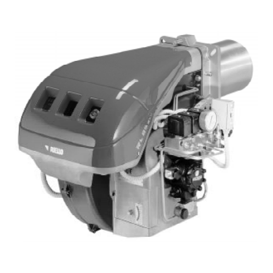
BRENNERBESCHREIBUNG (A) BURNER DESCRIPTION (A) DESCRIPTION BRULEUR (A) 1 ZŸndelektroden 1 Ignition electrodes 1 Electrodes d'allumage 2 UV Zelle 2 Cell UV 2 DŽtecteur UV 3 Flammkopf 3 Combustion head 3 T•te de combustion 4 Einstellschraube Flammkopf 4 Screw for combustion head adjustment 4 Vis pour rŽglage t•te de combustion 5 Schraube fŸr die Befestigung des GeblŠses 5 Screw for Þxing fan to ßange... -
Seite 10: Campi Di Lavoro
CAMPI DI LAVORO (A) La potenza del bruciatore varia in funziona- mento tra: ¥ una POTENZA MINIMA: area A; ¥ una POTENZA MASSIMA: area B. Diagrammi (A): Asse orizzontale : potenza bruciatore Asse verticale : pressione in camera di com- bustione Il punto di lavoro si trova tracciando una verti- cale dalla potenza desiderata ed una orizzon-... -
Seite 11: Firing Rates
REGELBEREICHE (A) FIRING RATES (A) PLAGES DE PUISSANCE (A) WŠhrend des Betriebs schwankt die Brennerlei- During operation, burner output varies between: Durant le fonctionnement, la puissance du brž- stung zwischen: ¥ MINIMUM OUTPUT: area A; leur varie entre: ¥ einer MINDESTLEISTUNG: Feld A; ¥... -
Seite 12: Installazione
La lunghezza, L (mm), disponibile •: Boccaglio 9): RL 55 BLU RL 65 BLU RL 85 BLU Per le caldaie con giro dei fumi anteriore 12), o con camera ad inversione di Þamma, eseguire una protezione in materiale refrattario 10), tra refrattario caldaia 11) e boccaglio 9). -
Seite 13: Installation
Flammrohr 9): RL 55 BLU RL 65 BLU RL 85 BLU Buse 9): RL 55 BLU RL 65 BLU RL 85 BLU Blast tube 9): RL 55 BLU RL 65 BLU RL 85 BLU FŸr Heizkessel mit vorderem Rauchumlauf 12) Pour les chaudi•res avec circulation des fumŽes... -
Seite 14: Scelta Dellõ Ugello
RL 55 BLU, portata massima gasolio = 40 kg/h Il diagramma (E) indica che per una portata di 40 kg/h il bruciatore RL 55 BLU necessita di una regolazione della testa di combustione a 3 tac- che circa, come illustrato in Þg. (D). -
Seite 15: Choice Of Nozzle
(E) avec le Example: der Brenner betrieben werden soll. plan antŽrieur de la bride 5)(D). RL 55 BLU, maximum light oil delivery = 40 kg/h Die Schraube 4)(D) soweit verdrehen, bis die Exemple: Diagram (E) indicates that for a delivery of 40 Kerbe in Diagramm (E) mit der vorderen FlŠche... -
Seite 16: Impianto Idraulico
IMPIANTO IDRAULICO ¥ ALIMENTAZIONE COMBUSTIBILE Circuito bitubo (A) Il bruciatore • dotato di pompa autoaspirante e perci˜, entro i limiti indicati nella tabella, • in grado di alimentarsi da solo. Cisterna pi• in alto del bruciatore A E' opportuno che la quota P non superi i 10 m per non sollecitare eccessivamente l'organo di tenuta della pompa e la quota V non superi i 4 m per rendere possibile l'autoinnesco della pompa... -
Seite 17: Hydraulic System
HYDRAULIKANLAGE HYDRAULIC SYSTEM INSTALLATION HYDRAULIQUE ¥ ¥ ¥ BRENNSTOFFZUF†HRUNG FUEL SUPPLY ALIMENTATION COMBUSTIBLE Zweistrangsystem (A) Double-pipe circuit (A) Circuit ˆ double tuyau (A) Der Brenner verfŸgt Ÿber eine selbstansau- The burner is equipped with a self-priming pump Le bržleur est muni d'une pompe ˆ aspiration gende Pumpe und kann sich daher, innerhalb which is capable of feeding itself within the limits automatique et par consŽquent, dans les limites... -
Seite 18: Impianto Elettrico
FACTORY-SET ELECTRICAL EQUIPMENT INSTALLATION ELECTRIQUE REALISEE EN USINE SCHEMA (A) RL 55 BLU - RL 65 BLU - RL 85 BLU Bruciatori RL 55 - 65 - 85 BLU ¥ I modelli RL 55-65-85 BLU lasciano la fabbrica previsti per alimentazione elettrica 400 V. -
Seite 19: Electrical System
ELEKTROANLAGE ELECTRICAL SYSTEM INSTALLATION ELECTRIQUE ELECTRICAL SYSTEM as set up by the manu- ELEKTROANLAGE werkseitig ausgefŸhrt INSTALLATION ELECTRIQUE effectuŽe en facturer usine SCHEMA (A) LAYOUT (A) Brenner RL 55 - 65 - 85 BLU SCHEMA (A) Burners RL 55 - 65 - 85 BLU ¥... - Seite 20 400 V, la protezione • assicurata lo stesso. NOTE I bruciatori RL 55 BLU - RL 65 BLU - RL 85 BLU lasciano la fabbrica previsti per alimentazione elettrica 400 V. Se l'alimentazione • 230 V, cam- biare il collegamento del motore (da stella a triangolo) e la taratura del rel•...
- Seite 21 Falls die Stromversorgung 230 changer la connexion du moteur (d'Žtoile ˆ trian- The RL 55 BLU - RL 65 BLU - RL 85 BLU burn- V betrŠgt, den Motoranschlu§ von Stern- auf gle) et le rŽglage du relais thermique.
-
Seite 22: Servomotore
SERVOMOTORE (A) Il servomotore regola contemporaneamente la serranda dell'aria, tramite la camma a proÞlo variabile, e il variatore di pressione. L'angolo di rotazione del servomotore • di 130° in 42 s. Non modiÞcare la regolazione fatta in fabbrica alle 5 camme di cui • dotato; solo controllare che esse siano come sotto riportato: Camma I : 130°... -
Seite 23: Servomotor
STELLANTRIEB (A) SERVOMOTOR (A) SERVOMOTEUR (A) Uber den Nocken mit variablem ProÞl steuert Le servomoteur r•gle en m•me temps le volet The servomotor provides simultaneous adjust- der Stellantrieb gleichzeitig die Luftklappe und dÕair par la came ˆ proÞl variable et le rŽgulateur ment of the air gate valve, by means of the vari- den Druckregler. -
Seite 24: Accensione Bruciatore
ACCENSIONE BRUCIATORE Chiudere i telecomandi e mettere l'interruttore 1)(A) in posizione "MAN". Ad accensione avvenuta, passare alla completa regolazione del bruciatore. REGOLAZIONE BRUCIATORE Per ottenere una regolazione ottimale del bru- ciatore • necessario effettuare l'analisi dei gas di scarico della combustione all'uscita della cal- daia. -
Seite 25: Burner Þring
Z†NDUNG DES BRENNERS BURNER FIRING ALLUMAGE BRULEUR Die Regelungen einschalten und den Schalter Close load controls and set switch 1)(A) to Fermer les tŽlŽcommandes et mettre l'interrup- 1)(A) in Stellung "MAN" setzen. "MAN". teur 1)(A) sur la position "MAN". Nach erfolgter ZŸndung den Brenner vollstŠndig After burner Þring a complete burner adjustment Apr•s avoir effectuŽ... - Seite 26 Regolazione aria Variare in progressione il proÞlo Þnale della camma 2)(A) agendo sulle viti 5). - Per aumentare la portata dÕaria avvitare le viti. - Per diminuire la portata dÕaria svitare le viti. 2 - Potenza MIN La potenza MIN va scelta entro il campo di lavoro riportato a pag.
- Seite 27 Lufteinstellung Adjusting air delivery RŽglage air †ber die Schrauben 5) das EndproÞl des Nok- Progressively adjust the end proÞle of cam 2)(A) ModiÞer en progression le proÞl Þnal de la came ken 2)(A) verŠndern. 2)(A) en agissant sur les vis 5). using adjustment screws 5).
-
Seite 28: Funzionamento Bruciatore
FUNZIONAMENTO BRUCIATORE AVVIAMENTO BRUCIATORE (A) - (B) ¥ 0 s : Chiusura telecomando TL, avvio motore. La pompa 3) aspira il combustibile dalla cisterna attraverso il condotto 1) ed il Þltro 2) e lo spinge sotto pressione in mandata. Il pistone 4) si solleva ed il combustibile ritorna in cisterna dai condotti 5)-7). -
Seite 29: Burner Operation
BRENNERBETRIEB BURNER OPERATION FONCTIONNEMENT BRULEUR ANFAHREN DES BRENNERS (A) - (B) DEMARRAGE BRULEUR (A) - (B) BURNER STARTING (A) - (B) ¥ 0 s : ¥ 0 s : ¥ 0 s : Einschalten der TL-Fernsteuerung, Anlassen Fermeture tŽlŽcommande TL, dŽmarrage Control device TL closes, the motor starts. -
Seite 30: Controlli Finali
CONTROLLI FINALI ¥ Oscurare la fotocellula e chiudere i teleco- mandi: il bruciatore deve avviarsi e poi fer- marsi in blocco dopo circa 5 s dall'accensione. ¥ Illuminare la fotocellula e chiudere i teleco- mandi: il bruciatore deve andare in blocco. ¥... -
Seite 31: Final Checks
ENDKONTROLLEN FINAL CHECKS CONTROLES FINAUX ¥ Die Photozelle verdunkeln und die Fernsteue- ¥ Obscure the photocell and switch off the con- ¥ Obscurcir la photocellule et fermer les tŽlŽ- rungen schlie§en: der Brenner mu§ einschal- trol devices: the burner should start and then commandes: le bržleur doit dŽmarrer et se ten und ca. -
Seite 32: Inconvenienti - Cause - Rimedi
SIMBOLO (1) INCONVENIENTE CAUSA PROBABILE RIMEDIO CONSIGLIATO Il bruciatore non si avvia - Un telecomando di limite o di sicurezza aperto..Regolarlo o sostituirlo - Blocco apparecchiatura......Sbloccare - Intervento pressostato olio (vedi pag. -
Seite 33: Stšrungen - Ursachen - Abhilfen
ZEICHEN (1) ST…RUNGEN M…GLICHE URSACHEN EMPFOHLENE ABHILFEN Brenner geht nicht an - Eine Grenz- oder Sicherheitsfernsteuerung offen ..Einstellen oder Auswechseln - GerŠteblockierung ....... . GerŠt entriegeln - Eingriff des …ldruckwachters (siehe Seite 23) . -
Seite 34: Fault - Probable Cause - Suggested Remedy
SYMBOL (1) FAULT PROBABLE CAUSE SUGGESTED REMEDY The burner does not start - A limit or safety control device is open ....Adjust or replace - Control box lock-out . -
Seite 35: Inconvžnients - Causes - Rem•Des
SYMBOLE (1) DEFAUT CAUSE PROBABLE REMEDE CONSEILLE Le bržleur ne dŽmarre pas - Une tŽlŽcommande de limite ou de sŽcuritŽ est ouverte . . La rŽgler ou la changer - Blocage coffret ........DŽbloquer le coffret - Intervention pressostat huile (voir page 23) . - Seite 36 R.B.L. Riello Bruciatori Legnago s.p.a. Via degli Alpini 1 I - 37045 Legnago (VR) Tel.: +442 / 630111 Fax: +442 / 21980 Con riserva di modiÞche - €nderungen vorbehalten! - Subject modiÞcations - Sous rŽserve de modiÞcations...