GF CONTAIN-IT Plus 546 Bedienungsanleitung
Kugelhahn

Verwandte Anleitungen für GF CONTAIN-IT Plus 546


Inhaltszusammenfassung für GF CONTAIN-IT Plus 546
- Seite 1 CONTAIN-IT Plus Kugelhahn Typ 546 CONTAIN-IT Plus Bedienungsanleitung Ball Valve Type 546 Instruction Manual...
-
Seite 3: Inhaltsverzeichnis
CONTAIN-IT Plus Kugelhahn Typ 546/ CONTAIN-IT Plus Ball Valve Type 546 Betriebsanleitung/ Instruction Manual Einleitung ..........................2 Aufbau CONTAIN-IT Plus Kugelhahn 546 ................3 Installation .........................4 Schritt 1: Einbau des CONTAIN-IT Plus Kugelhahns 546 ..........4 Schritt 2: Vorbereitung der Druckprüfung................5 Schritt 3: Druckprüfung der Innenleitung................7 Schritt 4: Zusammenbau des CONTAIN-IT Plus Kugelhahns 546........7 Aus- und Einbau des Kugelhahns..................9 4.1. -
Seite 4: Einleitung
Doppelrohr-Armaturen von +GF+ Rohrleitungssysteme werden als einbaufertige Systemeinheit geliefert und analog einem Doppelrohrfitting verarbeitet. Das Prinzip der Doppelrohr-Verbindungstechnik von +GF+ basiert darauf, dass zuerst die Innenleitung nach der von Ihnen gewählten Verbindungstechnik verbunden wird. Folgende Verbindungstechniken und Materialien stehen zur Auswahl:... -
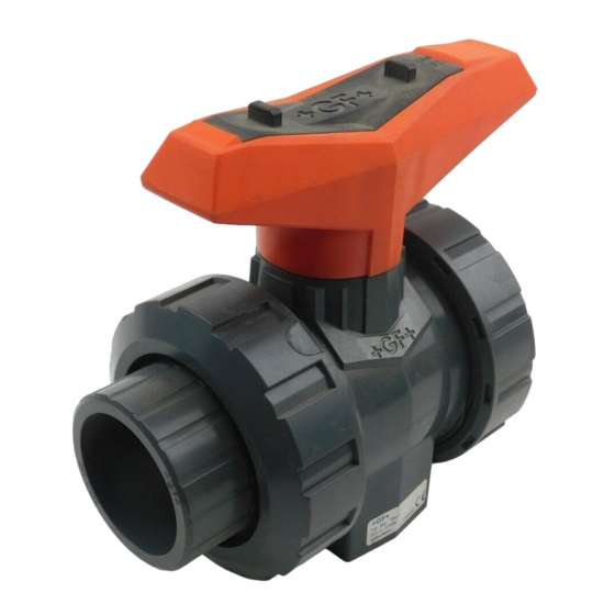
Seite 5: Aufbau Contain-It Plus Kugelhahn 546
2. Aufbau CONTAIN-IT Plus Kugelhahn 546 1. Schutzgehäuse 2. Zapfen 3. Einlegteil 4. Einschraubteil 5. Überwurfmutter Schutzgehäuse 6. Handhebel 7. Muttern und Schrauben (zur Befestigung des Hebels) 8. Abstützungen PE 9. Kugelhahn Typ 546 (Zentralteil) 10. Überwurfmutter Kugelhahn Typ 546 11. -
Seite 6: Installation
3. Installation Bevor der Doppelrohr Kugelhahn 546 in Betrieb genommen werden kann, sind die folgenden 4 Schritte zum Einbau notwendig: Schritt 1: Einbau des CONTAIN-IT Plus Kugelhahns 546 Beachten Sie, dass die Kugelhahnstellung auf „AUF“ sein muss (Abbildung 1)! Zuerst wird das Innenrohr des Kugelhahns mit dem Innenrohr der Doppelrohrleitung verbunden. -
Seite 7: Schritt 2: Vorbereitung Der Druckprüfung
Schritt 2: Vorbereitung der Druckprüfung Vorgehensweise: 1. Achten Sie darauf, dass der rote Handhebel parallel zur Hauptleitung steht. (Abbildung 1). Abbildung 1 2. Lösen Sie die Muttern am Handhebel und entfernen Sie diesen. (Abbildung 2). Abbildung 2 3. Lösen Sie die Überwurfmuttern des Schutzgehäuses beidseitig und schieben Sie diese und das Einlegteil zur Seite. - Seite 8 5. Ziehen Sie den Zapfen aus dem Gehäuse. Eine Einkerbung am Zapfen ermöglicht die Verwendung eines Schrauben- drehers. (Abbildung 5). Abbildung 5 6. Schieben Sie das Gehäuse zur Seite des Einlegteils. Der Kugelhahn ist nun zugänglich (Abbildung 6). Abbildung 6 6/27...
-
Seite 9: Schritt 3: Druckprüfung Der Innenleitung
Schritt 3: Druckprüfung der Innenleitung Vorgehensweise: 1. Öffnen Sie das Schutzgehäuse (Schritt 2), um eine mögliche Leckage während der Druckprüfung feststellen zu können. 2. Die Druckprüfung ist mit Wasser oder ungefährlichen Medien durchzuführen. Siehe dazu DVS 2210-2 mit Hinweis auf DVS 2210-1, Beiblatt 2, sowie die Anweisungen in der oben erwähnten Montage- und Betriebsanleitung für den Kugelhahn Typ 546. - Seite 10 Abbildung 9 3. Kontrollieren Sie, ob der Zapfen mit den seitlichen Führungen des Aufsatzes bündig ist. (Abbildung 10). Abbildung 10 4. Schrauben Sie das Einschraubteil in das Schutzgehäuse (Linksgewinde!) und ziehen es mit dem Zapfenschlüssel an. (Abbildung 11). Abbildung 11 5.
-
Seite 11: Aus- Und Einbau Des Kugelhahns
4. Aus- und Einbau des Kugelhahns 4.1. Öffnen des Schutzgehäuses Vorgehensweise: siehe Kapitel 3 - Schritt 2 4.2. Ausbau des Kugelhahns Vorgehensweise: 1. Überwurfmuttern des Kugelhahns lösen. 2. Kugelhahn aus der Innenleitung nehmen 3. Revisionsarbeiten entsprechend der Bedienungsanleitung des Kugelhahns Typ 546 durchführen 4.3. -
Seite 12: Nachrüstung Von Antrieben Auf Den Contain-It Plus Kugelhahn 546
5. Nachrüstung von Antrieben auf den CONTAIN-IT Plus Kugelhahn 546 Der CONTAIN-IT Plus Kugelhahn 546 kann mit den Antrieben EA11, EA21 und PA21 gemäss nachfolgender Beschreibung aufgerüstet werden. Bitte beachten Sie jeweils auch die Anleitungen der jeweiligen Antriebe. Zur Aufrüstung eines Antriebes benötigen Sie das Adapter Set 700 238 796. Dieses Adapter Set beinhaltet folgende Teile: •... - Seite 13 3. Stecken Sie die Kupplung in den Anschluss des Antriebs. (Abbildung 16). Abbildung 16 4. Montieren Sie die Adapterplatte mit vier Senkschrauben an den Antrieb. (Abbildung 17). Abbildung 17 5. Setzen Sie die Reduzierhülse auf den Zapfen des Kugelhahns. (Abbildung 18). Abbildung 18 6.
- Seite 14 7. Der Doppelrohr Kugelhahns 546 und der Antrieb sind nun betriebsbereit. (Abbildung 20). Abbildung 20 12/27...
-
Seite 15: Ersatzdichtungen Für Den Contain-It Plus Kugelhahn 546
6. Ersatzdichtungen für den CONTAIN-IT Plus Kugelhahn 546 6.1. Zapfen (siehe S.3 Nr. 15) Dimension Kugelhahn Artikelnummer Menge Dimension Beschreibung d20/50 – d32/50 748 410 103 3.54mm x 29.75mm O-Ring EPDM 749 410 103 3.54mm x 29.75mm O-Ring FPM d40/75 – d63/110 748 410 027 3.54mm x 37.69mm O-Ring EPDM... - Seite 32 GF Piping Systems – worldwide at home Our sales companies and representatives www.piping.georgfischer.com ensure local customer support in over 100 countries. The technical data is not binding. They neither constitute expressly Adding Quality to People’s Lives warranted characteristics nor guaranteed properties nor a guaranteed durability.