GF PV94 Montageanleitung
Vorsteuerventil
Quicklinks
GF Piping Systems
Mounting instructions
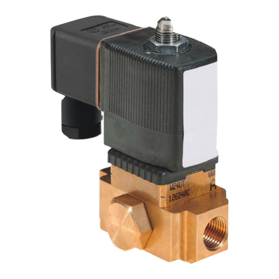
Type PV94/PV95 3/2-way
pilot valve
Montageanleitung
Typ PV94/PV95 3/2-Wege-
Vorsteuerventil
1271114
MA_00070 / 0a (03.2021)
© Georg Fischer Piping Systems Ltd
CH-8201 Schaffhausen/Switzerland
+41 52 631 30 26 / info.ps@georgfischer.com / www.gfps.com
Overview
1
Übersicht
1
4
2
3
6
5
Description
Beschreibung
Cable plug
Gerätesteckdose
a
Type label
Typenschild
s
Manual control
Handbetätigung
d
Coil assembly
Spulenmontage
f
Pressure connection / Outlet
Druckanschluss/ Ausgang
g
Flow direction
Durchflussrichtung
h
Mounting position
5
Montageposition
Note
Mounting position as desired, actuator preferably upwards.
Hinweis
Einbaulage beliebig, vorzugsweise Antrieb nach oben.
Preparation for electrical connection
9
Vorbereitung für elektrischen Anschluss
PV95 C 2,0 FKM MS
G1/8 P N 0 - 10 bar
24V
50 Hz
8 W
00450000
W14UN
WARNING!
Risk of injury due to electrical shock!
► Before reaching into the system, switch off the power supply
and secure to prevent reactivation.
► Note the voltage and current type as specified on the type label.
WARNUNG!
Verletzungsgefahr durch Stromschlag!
► Vor Eingriffen in das Gerät oder die Anlage Spannung
abschalten und vor Wiedereinschalten sichern.
► Spannung und Stromart laut Typschild beachten.
Our General Terms of Sale apply.
Es gelten unsere Allgemeinen Verkaufsbedingungen.
EC declaration of conformity
Georg Fischer Piping Systems Ltd, 8201 Schaffhausen (Switzerland) declares that the
products listed below comply with the requirements of the European Directive(s) and
may therefore bear the CE marking.
Modifications to the products that affect the specified technical data and the intended
use make this declaration invalid.
Additional information can be found in the "GF Planning Fundamentals".
EG-Konformitätserklärung
Georg Fischer Rohrleitungssysteme AG, 8201 Schaffhausen (Schweiz) erklärt, dass
nachfolgend aufgeführte Produkte den Anforderungen der Europäischen Richtlinie(n)
entspricht und somit die CE-Kennzeichnung tragen dürfen.
Änderungen an den Produkten, die Auswirkungen auf die angegebenen technischen
Daten und den bestimmungsgemässen Gebrauch haben, machen diese Erklärung
ungültig.
Zusätzliche Informationen können den «GF Planungsgrundlagen» entnommen werden.
Product group
Type designation
Additional directives and harmonized design
Produktgruppe
Typenbezeichnung
standards
Weitere Richtlinien und Harmonisierte
Bauart-Normen
Pilot valve
Type PV94/PV95
2006/95/EG*
2014/30/EU
EN61010-1:2010
EN50178:1997
EN60664-1:2007
EN60204-1:2006
*valid for 110-230V types / *gültig für 100-230V Typen.
Schaffhausen, den 12.03.2021
Bastian Lübke
Head of Global R&D
Georg Fischer Piping Systems Ltd.
CH-8201 Schaffhausen (Switzerland)
Complete technical documentation via QR
code or at
Vollständige technische Dokumentation über
QR-Code oder unter
www.gfps.com/is-solenoid-valves
Operating Instructions_2102/01_Euml_00804179
Type label
2
Typenschild
1
2
3
4
5
PV95 C 2,0 FKM MS
G1/8 P N 0 - 10 bar
6
24V
50 Hz
8 W
7
00450000
W14UN
9
8
Description
Beschreibung
Type
Typ
a
Circuit function
Wirkungsweise
s
Nominal diameter
Nennweite
d
Sealing material
Dichtungswerkstoff
f
Body material
Gehäusewerkstoff
g
Connection thread, Operating
Anschlussart, Betriebsdruck
h
pressure
Voltage, Frequency,
Spannung, Frequenz, Leistung
j
Power consumption
Manufacturer code
Hersteller-Code
k
Id. Number
Identnummer
l
Before installation
6
Vor dem Einbau
S
P
A
Procedure
► Clean any contamination from the pipes.
► Install a dirt filter (S) for particles 0.2 to 0.4 mm upstream of
the pressure connection (P).
► Make sure that the device is not electrically powered.
► Completely relieve the pressure in the pipe before installation.
Vorgehensweise
► Rohrleitungen von eventuellen Verschmutzungen säubern.
► Vor dem Druckanschluss (P) einen Schmutzfilter (S) für Partikel
0.2 bis 0.4 mm einbauen.
► Sicherstellen, dass das Gerät nicht mit Strom versorgt wird.
► Druck in der Rohrleitung vor einem Einbau vollständig abbauen.
Electrical connection of the cable plug
10
Elektrischer Anschluss der Gerätesteckdose
Procedure
► Connect cable plug to cable (cable cross-section 3 x 0.75 mm²).
► Connect protective conductor and check electrical continuity.
If the protective conductor is not connected, there is a risk of
electric shock!
Vorgehensweise
► Gerätesteckdose an Kabel anschliessen (Kabelquerschnitt 3 x
0,75 mm²).
► Schutzleiter anschliessen und elektrischen Durchgang prüfen.
Bei fehlendem Schutzleiterkontakt zwischen Spule und Gehäuse
besteht die Gefahr des Stromschlags!
N°
i
Other applicable documents
Planning Fundamentals Industry
700671687
Abbreviations
FC
Function Failsafe Closed
Technical data
PV94
PV95
Nominal diameter
DN1.2
DN2
Presure range
0-10 bar (AC) / 0-6 bar (DC) 0 – 10 bar
Housing material
Brass (Nickel plated),
Brass (flange housing)
Polyamide
Aluminum anodized
(Connector housing)
Coil material
Polyamide
Sealing material
NBR
FKM
Media
Neutral gases and fluids
Media temperature
-10 °C to +60°C
-10 °C to +100 °C
Ambient temperature
-10 °C to +40°C
Max. + 55 °C
Viscosity
Max. 21 mm
2
/s
Port connection
G⅛"
G⅛", G1/4"
Air connection
G⅛", NPT ⅛", tube fitting
G1/4", NPT ⅛"
Ø6mm
Suply voltage
24 V DC
24 V, 50 – 60 Hz
110 V, 50 – 60 Hz
230 V, 50 – 60 Hz
Voltage tolerance
±10 %
Rated duty
Continuous duty 100 % ED
Electric connection
Per DIN EN 175301-803
Per DIN EN 175301-803
Form C
Form A
Protection class
IP65 with cable plug
Circuit function
Description
C
C
3/2-way valve;
A
FC; closed in rest position
P
R
Coil assembly
3
Spulenmonetage
2
3
1
Description
Beschreibung
O-ring
O-Ring
a
Nut
Mutter
s
Tightening torque
Anzugsmoment
d
PV94: max. 2.8 Nm
PV94: max. 2.8 Nm
PV95: max. 5 Nm
PV95: max. 5 Nm
7
Flow direction
Durchflussrichtung
Note
► Observe direction of flow. The arrow or letter on the body
indicates the direction of flow.
► Functioning of the device is only ensured if the circuit function is
maintained.
Hinweis
► Durchflussrichtung beachten. Der Pfeil bzw. die Buchstaben auf
dem Gehäuse kennzeichnen die Durchflussrichtung.
► Die Funktion des Geräts ist nur sichergestellt, wenn die
Wirkungsweise eingehalten wird.
Mounting the cable plug
11
Montage der Gerätesteckdose
1
2
3
Description
Beschreibung
Cable plug
Gerätesteckdose
a
Seal
Dichtung
s
Tightening torque
Anzugsmoment
d
PV94: Max. 0.3 Nm
PV94: Max. 0.3 Nm
PV95: Max. 1 Nm
PV95: Max. 1 Nm
Procedure
► Tighten cable plug to the device, observing max. tightening
torque.
► Check that seal is fitted correctly.
Vorgehensweise
► Gerätesteckdose an Gerät festschrauben, dabei maximales
Drehmoment beachten.
► Korrekten Sitz der Dichtung überprüfen.
i
N°
Mitgeltende Unterlagen
Planning Fundamentals Industry
700671686
Abkürzungen
FC
Wirkungsweise Federkraft schliessend
Technische Daten
PV94
PV95
Nennweite
DN1.2
DN2
Druckbereich
0-10 bar (AC) / 0-6 bar (DC) 0 – 10 bar
Gehäusewerkstoff
Messing (vernickelt),
Messing (Flanschgehäuse)
Polyamid
Aluminium eloxiert
(Anschlussgehäuse)
Spulenwerkstoff
Polyamid
Dichtwerkstoff
NBR
FKM
Medien
Neutrale Gase und Flüssigkeiten
Medientemperatur
-10 °C bis +60°C
-10 °C bis +100 °C
Umgebungstemperatur
-10 °C bis +40°C
Max. + 55 °C
Viskosität
Max. 21 mm
2
/s
Leitungsanschluss
G⅛"
G⅛", G1/4"
Druckluftanschluss
G⅛", NPT ⅛",
G1/4", NPT ⅛"
Schlauchsteckverbinder
Ø6mm
Betriebsspannung
24 V DC
24 V, 50 – 60 Hz
110 V, 50 – 60 Hz
230 V, 50 – 60 Hz
Spannungstoleranz
±10 %
Nennbetriebsart
Dauerbetrieb 100 % ED
Elektrischer Anschluss
Nach DIN EN 175301-803
Nach DIN EN 175301-803
Form C
Form A
Schutzart
IP65 mit Gerätesteckdose
Wirkungsweise
Beschreibung
C
C
3/2-Wege-Ventil,
A
FC; in Ruhestellung geschlossen
P
R
Manual control
4
Handbetätigung
Caution
When the manual control is locked, the valve can no longer be
actuated electrically.
Vorsicht
Bei arretierter Handbetätigung kann das Ventil elektrisch nicht
mehr betätigt werden.
Installation
8
Einbau
3
1
2
Procedure
1. Use PTFE tape as seal material. Sealing material must not get
into the device.
2. Determine the maximum screw-in depth of the connecting
threads as this does not comply with any standard.
3. Hold the device with a suitable tool (open-end wrench) on the
body; screw into the pipe.
Caution
► Caution risk of breakage! Do not use the coil as a lever arm.
► Valve body must not be installed under tension.
Vorgehen
1. Als Dichtwerkstoff PTFE-Band verwenden. Dichtmaterial darf
nicht in das Gerät gelangen.
2. Maximale Einschraubtiefe der Anschlussgewinde ermitteln, da
diese keiner Norm entspricht.
3. Gerät mit geeignetem Werkzeug (Gabelschlüssel) am Gehäuse
festhalten und in die Rohrleitung einschrauben.
Vorsicht
► Vorsicht Bruchgefahr! Spule nicht als Hebelarm benutzen.
► Ventilgehäuse darf nicht verspannt eingebaut werden.
Malfunctions
12
Störungen
► If malfunctions occur, check port connections, operating
pressure and supply voltage. A stuck armature in AC coils
causes coil overheating.
Malfunction
Possible cause
Valve does not switch
Short-circuit or coil interrupted
Medium pressure outside the permitted
pressure range
Manual control locked
Valve does not close
Internal space of the valve is dirty
Manual control locked
► Bei Störungen Anschluss, Betriebsdruck und Spannung
überprüfen. Festsitzender Anker bewirkt bei Wechselstrom-
spulen Spulenüberhitzung.
Störung
Mögliche Ursache
Ventil schaltet nicht
Kurzschluss oder Spulenunterbrechung
Mediumsdruck ausserhalb des zulässigen
Druckbereichs
Handbetätigung arretiert
Ventil schliesst nicht
Innenraum des Ventils verschmutzt
Handbetätigung arretiert

Verwandte Anleitungen für GF PV94


Inhaltszusammenfassung für GF PV94
- Seite 1 Modifications to the products that affect the specified technical data and the intended Wirkungsweise Federkraft schliessend Function Failsafe Closed use make this declaration invalid. Type PV94/PV95 3/2-way Additional information can be found in the “GF Planning Fundamentals”. pilot valve Technical data PV94 PV95...
- Seite 2 Intended use Bestimmungsgemässe Verwendung The PV94/PV95 pilot valve is a direct-acting plunger valve. The 3/2-way solenoid valve is used to activate single-acting pneumatic Das Vorsteuerventil PV94/PV95 ist ein direktwirkendes Hubankerventil. Das 3/2-Weg-Magnetventil wird zur Ansteuerung von einfach actuators indoors. The PV94 is designed for dimensions up to DN50, the PV95 for DN65-DN150.