Herunterladen Inhalt Inhalt Diese Seite drucken
GF 604 Betriebsanleitung

GF 604 Betriebsanleitung

Pneumatisches membranventil
Vorschau ausblenden Andere Handbücher für 604:
Inhaltsverzeichnis

Werbung

Verfügbare Sprachen
  • DE

Verfügbare Sprachen

  • DEUTSCH, seite 34
GF Piping Systems
Pneumatic
diaphragm valve
type 604/605
Operating Instructions
Pneumatisches
Membranventil
Typ 604/605
Betriebsanleitung
Robinet à membrane
pneumatique
type 604/605
Manuel d'utilisation
Válvula de membrana
tipo 604/605
Manual de instrucciones
604/605型气动隔膜阀
使用说明书
2007559 Pneumatic diaphragm valve type 604/605
MA_00124 / DE EN FR ES ZH / 00 (12.21)
© Georg Fischer Piping Systems Ltd
CH-8201 Schaffhausen/Switzerland
+41 52 631 30 26/info.ps@georgfischer.com
www.gfps.com

Werbung

Inhaltsverzeichnis
loading

Inhaltszusammenfassung für GF 604

  • Seite 1 Válvula de membrana tipo 604/605 Manual de instrucciones 604/605型气动隔膜阀 使用说明书 2007559 Pneumatic diaphragm valve type 604/605 MA_00124 / DE EN FR ES ZH / 00 (12.21) © Georg Fischer Piping Systems Ltd CH-8201 Schaffhausen/Switzerland +41 52 631 30 26/info.ps@georgfischer.com www.gfps.com...
  • Seite 2: Inhaltsverzeichnis

    Content Pneumatic diaphragm valve type 604/605 Pneumatisches Membranventil Typ 604/605 Robinet à membrane pneumatique type 604/605 63 Válvula de membrana neumática tipo 604/605 604/605型气动隔膜阀...
  • Seite 3: Pneumatic Diaphragm Valve Type 604

    GF Piping Systems Pneumatic diaphragm valve type 604/605 Operating Instructions...
  • Seite 4 GF Piping Systems Translation of the original instruction manual Disclaimer The technical data are not binding. They neither constitute expressly warranted characteristics nor guaranteed properties nor a guaran- teed durability. It is subject to modification. Our General Terms of Sale apply.
  • Seite 5 Operating Instructions Pneumatic diaphragm valve type 604/605 Table of contents About this document Other applicable documents Symbols Abbreviations Terms used Safety Information Meaning of the signal words Observe instruction manual Safety and responsibility Notes for service and operating personnel Product description...
  • Seite 6 Pneumatic diaphragm valve type 604/605 Operating Instructions Measures during operation Service Maintenance plan Removal and disassembly Replacing the diaphragm Troubleshooting Accessories and Spare Parts Accessories Disposal...
  • Seite 7: About This Document

    Operating Instructions Pneumatic diaphragm valve type 604/605 About this document Other applicable documents Document Georg Fischer Planning Fundamentals Industry 700671687 Data sheet www.gfps.com/is-manuals-valves Chemical resistance www.gfps.com These documents are available from the Georg Fischer Piping Systems Sales Company or at www.gfps.com.
  • Seite 8: Safety Information

    Pneumatic diaphragm valve type 604/605 Operating Instructions Safety Information The safety instructions apply to use as described under "Intended use". The safety instructions do not cover the following cases: Incidental events occurring during installation, operation and service. • The operator is responsible for the local and site-related safety regulations.
  • Seite 9: Notes For Service And Operating Personnel

    Operating Instructions Pneumatic diaphragm valve type 604/605 Notes for service and operating personnel The following target groups are addressed in these operating instructions: Operators Operators are instructed in the operation of the product and observe the safety guidelines. Service personnel The service personnel has professional technical training and performs installation, putting into operation, as well as maintenance work.
  • Seite 10: Product Description

    Product description Intended use The type 604/605 pneumatic diaphragm valve is designed exclusively for installation in a compatible industrial piping system to shut off, pass or regulate the flow of approved medium. It must be used exclusively within the chemical resistance of the entire fittings and all components.
  • Seite 11: Type Overview

    Operating Instructions Pneumatic diaphragm valve type 604/605 Type overview Type 604 Type 605 True Union Spigot Design and function 3.5.1 Construction The design of the valve is identical for the valve body types, except for the connections. Item Name Optical position indicator...
  • Seite 12 Pneumatic diaphragm valve type 604/605 Operating Instructions 3.5.2 Mode FC mode FO mode DA mode In the non-operative state, the valve is In the non-operative state, the valve is The valve has no defined home position. closed by spring resistance. When the opened by spring resistance.
  • Seite 13: Identification

    Operating Instructions Pneumatic diaphragm valve type 604/605 Identification 3.6.1 Diaphragm valve Item Name Order number Type 604 d20DN15 Valve body material Functional scheme 161624012 Diaphragm material PVC-U EPDM PN10 Serial number I Iz40.23-3 Max. control pressure Fail close [FC] Pmax 6bar...
  • Seite 14: Technical Data

    Pneumatic diaphragm valve type 604/605 Operating Instructions Technical Data 3.7.1 Specifications Specifications Allowed medium Liquid and gaseous medium which do not negatively affect the physical and chemical properties of the respective valve body and diaphragm material during normal mode. Information on chemical resistance is available from the Georg Fischer Piping Systems Sales Company or at www.gfps.com.
  • Seite 15: Air Connection

    Operating Instructions Pneumatic diaphragm valve type 604/605 3.7.2 Air connection connection of the control medium d20/DN15 G 1/4" NOTE! Relationship between medium pressure and loaded spring components! The closing force of the actuators is designed for the specified PN pressure level. Operation at very low medium pressures and very powerful actuators leads to increased diaphragm wear.
  • Seite 16: Control Volume

    Pneumatic diaphragm valve type 604/605 Operating Instructions Max. control pressure PS [bar] Diaphragm EPDM, EPDM, PTFE material PTFE PTFE DN15 Note: For optimum service life of the fittings, it is recommended to set the PS control pressure based on the medium pressure - see control pressure diagrams.
  • Seite 17: Pressure Losses

    Operating Instructions Pneumatic diaphragm valve type 604/605 3.7.6 Kv 100-values Inch Kv 100 Cv 100 kv 100 (mm) (mm) (") (l/min) (US gal./min) 3.7.7 Flow rate x Open angle (%) 100.0 y Kv, Cv value (%) 90.0 80.0 70.0 60.0 50.0...
  • Seite 18: Installation

    Pneumatic diaphragm valve type 604/605 Operating Instructions Installation Preparation DANGER! Valve not suitable for application! The valve has product-specific characteristics, installation dimensions and connections. The use of a valve unsuitable for the appli- cation can cause personal injury and damage to property as well as endanger the environment.
  • Seite 19: Installation Process

    Operating Instructions Pneumatic diaphragm valve type 604/605 Installation process ► Always install the valve in the open position. DANGER! Use of hazardous and non-approved medium! Non-approved chemically aggressive or hot medium can attack materials, cause personal injury and endanger the environment.
  • Seite 20: Tops Identification

    Operating Instructions 4.2.2 Adhesive joint PVC-U, PVC-C and ABS - with types 604, 605 Only join identical materials. After the curing time, flush the pipeline section with water without pressure (see chapter "Jointing technology" in Georg Fischer Planning Fundamentals Industry).
  • Seite 21: Connecting Control Pressure

    Operating Instructions Pneumatic diaphragm valve type 604/605 Connecting control pressure CLOSE OPEN Control air connection G 1/4“ 4.4.1 Diaphragm valve with mode FC / FO Diaphragm valve with mode FC Diaphragm valve with mode FO ► Use 3/2-way pressure solenoid valves (e.g. PV94 or MNL532).
  • Seite 22: Putting Into Operation

    Pneumatic diaphragm valve type 604/605 Operating Instructions Putting into operation Preparation Check that it is working: Close the valve and open it again. Flush piping system. Pressure testing The same instructions apply to the pressure testing of valves as to the pipe (see chapter "Processing and installation" in Georg Fi- scher Planning Fundamentals Industry).
  • Seite 23: Normal Mode

    Operating Instructions Pneumatic diaphragm valve type 604/605 Normal mode Measures during operation DANGER! Use of hazardous and non-approved medium! Non-approved chemically aggressive or hot medium can attack materials, cause personal injury and endanger the environment. Components not in contact with the medium can be attacked by leakage inside the valve.
  • Seite 24: Service

    Pneumatic diaphragm valve type 604/605 Operating Instructions Service Maintenance plan Interval Maintenance task ► Check the connection between top part and valve body for Regularly leakage. ► Press to check functionality of permanently open or closed 1 - 2 times a year diaphragm valves.
  • Seite 25: Removal And Disassembly

    Operating Instructions Pneumatic diaphragm valve type 604/605 Removal and disassembly DANGER! Uncontrolled escape of the medium! If the pressure in the piping system has not been completely relieved, the medium can escape in an uncontrolled manner. Depending on the type of medium, risk of injury may exist.
  • Seite 26: Replacing The Diaphragm

    Pneumatic diaphragm valve type 604/605 Operating Instructions Replacing the diaphragm The frequency for replacing the diaphragm depends on the number of actuator cycles and the medium used. The diaphragm can be checked by professionally disassembling the upper part. NOTE! The diaphragm is a consumable part! With heavy usage the diaphragm is excessively worn and needs to be change more frequently.
  • Seite 27 Operating Instructions Pneumatic diaphragm valve type 604/605 Install a new diaphragm in the same position as the old diaphragm. ► Place the actuator straight up for the first rotations, this is so that the grub screw of the diaphragm holder can grip the dia- phragm.
  • Seite 28 Pneumatic diaphragm valve type 604/605 Operating Instructions Tighten upper housing part until... a gap dimension of 0.5mm to 1mm is reached between the valve body and the upper housing part... • and the semicircular indicator on the upper housing part is aligned with the friction lock on the valve body.
  • Seite 29: Troubleshooting

    Operating Instructions Pneumatic diaphragm valve type 604/605 Troubleshooting Malfunction Possible Cause Troubleshooting ► Tighten connection and replace Leakage to the outside at flange connec- Temperature change tion gasket if necessary. ► Replace gasket. Gasket defective ► Tighten the connection hand-tight.
  • Seite 30 Pneumatic diaphragm valve type 604/605 Operating Instructions ► Select the control pressure accor- Diaphragm wears out prematurely Control pressure too high ding to the corresponding control pressure diagram. ► Check the (FC, FO, DA) functions and Function and connections for control medium do not match related connections.
  • Seite 31: Accessories And Spare Parts

    Operating Instructions Pneumatic diaphragm valve type 604/605 Accessories and Spare Parts CAUTION! Do not make any changes to the product! Material damage and/or risk of injury due to modifications to the product or incompatible spare parts. ► Secure the system/device against unintentional operation.
  • Seite 32 GF Piping Systems Worldwide at home Our sales companies and representatives ensure local customer support in more than 100 countries. www.gfps.com Argentina / Southern South America France Mexico / Northern Latin America Singapore Georg Fischer Central Plastics Sudamérica S.R.L. Georg Fischer SAS Georg Fischer S.A.
  • Seite 33: Pneumatisches Membranventil Typ 604

    GF Piping Systems Pneumatisches Membranventil Typ 604/605 Betriebsanleitung...
  • Seite 34 GF Piping Systems Originalbetriebsanleitung Haftungsausschluss Die technischen Daten sind unverbindlich. Sie gelten nicht als zugesicherte Eigenschaften oder als Beschaffenheits- oder Haltbarkeits- garantien. Änderungen vorbehalten. Es gelten unsere Allgemeinen Verkaufsbedingungen.
  • Seite 35 Betriebsanleitung Pneumatisches Membranventil Typ 604/605 Inhaltsverzeichnis Zu diesem Dokument Mitgeltende Dokumente Symbole Abkürzungen Verwendete Begriffe Sicherheitshinweise Bedeutung der Signalwörter Betriebsanleitung beachten Sicherheit und Verantwortung Hinweise für Service- und Bedienpersonal Produktbeschreibung Bestimmungsgemässe Verwendung Nicht bestimmungsgemässe Verwendung EG-Konformitätserklärung Typenübersicht Aufbau und Funktion...
  • Seite 36 Pneumatisches Membranventil Typ 604/605 Betriebsanleitung Massnahmen während Betrieb Wartung Wartungsplan Ausbau und Demontage Auswechseln der Membrane Störungsbehebung Zubehör und Ersatzteile Zubehör Entsorgung...
  • Seite 37: Zu Diesem Dokument

    Betriebsanleitung Pneumatisches Membranventil Typ 604/605 Zu diesem Dokument Mitgeltende Dokumente Dokument Georg Fischer Planungsgrundlagen Industrie 700671687 Datenblatt www.gfps.com/is-manuals-valves Chemische Beständigkeit www.gfps.com Diese Unterlagen sind über die Georg Fischer Vertriebsgesellschaft oder unter www.gfps.com erhältlich. Symbole Symbol Bedeutung Aufzählung in nicht definierter Reihenfolge.
  • Seite 38: Sicherheitshinweise

    Pneumatisches Membranventil Typ 604/605 Betriebsanleitung Sicherheitshinweise Die Sicherheitshinweise gelten für den Einsatz wie beschrieben unter „Bestimmungsgemässe Verwendung“. Die Sicherheitshinweise decken folgende Fälle nicht ab: Bei Installation, Betrieb und Wartung zufällig auftretende Ereignisse. • Für die lokalen und ortsbezogenen Sicherheitsbestimmmungen ist der Betreiber verantwortlich.
  • Seite 39: Hinweise Für Service- Und Bedienpersonal

    Betriebsanleitung Pneumatisches Membranventil Typ 604/605 Hinweise für Service- und Bedienpersonal Folgende Zielgruppen werden in dieser Betriebsanleitung angesprochen: Bediener Bediener sind in die Bedienung des Produktes eingewiesen und befolgen die Sicherheitsvorschriften. Servicepersonal Das Servicepersonal verfügt über eine fachtechnische Ausbildung und führt die Installation, Inbetriebnahme, sowie Wartungsarbei- ten durch.
  • Seite 40: Produktbeschreibung

    Produktbeschreibung Bestimmungsgemässe Verwendung Das pneumatische Membranventil Typ 604/605 ist ausschliesslich dazu bestimmt in ein dazu kompatibles industrielles Rohrlei- tungssystem eingebaut zu werden und dort zugelassene Medien abzusperren, durchzuleiten oder den Durchfluss zu regeln. Es darf ausschliesslich innerhalb der chemischen Beständigkeit der gesamten Armatur und aller Komponenten eingesetzt werden.
  • Seite 41: Typenübersicht

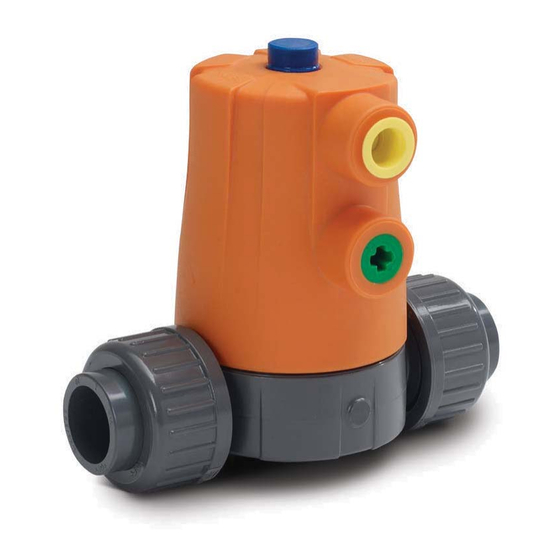
    Betriebsanleitung Pneumatisches Membranventil Typ 604/605 Typenübersicht Typ 604 Typ 605 Verschraubung Stutzen Aufbau und Funktion 3.5.1 Aufbau Der konstruktive Aufbau des Ventils ist bei den Ventilkörper-Typen, mit Ausnahme der Anschlüsse identisch. Pos. Name Optische Stellungsanzeige Anschluss für Steuerdruck zum Schliessen Anschluss für Steuerdruck zum Öffnen...
  • Seite 42: Funktion

    Pneumatisches Membranventil Typ 604/605 Betriebsanleitung 3.5.2 Funktion Funktion FC Funktion FO Funktion DA Im Ruhezustand ist das Ventil durch Im Ruhezustand ist das Ventil durch Das Ventil hat keine definierte Grundpo- Federkraft geschlossen. Wird der Federkraft geöffnet. Wird der Stellantrieb sition.
  • Seite 43: Identifikation

    Betriebsanleitung Pneumatisches Membranventil Typ 604/605 Identifikation 3.6.1 Membranventil Pos. Name Bestellnummer Type 604 d20DN15 Ventilkörperwerkstoff Funktionsweise 161624012 Membranwerkstoff PVC-U EPDM PN10 Seriennummer I Iz40.23-3 Max. Steuerdruck Fail close [FC] Pmax 6bar CE-Kennzeichnung und Zulassungen Nenndruck 0000000 000 swiss made Dimension www.gfps.com...
  • Seite 44: Technische Daten

    Pneumatisches Membranventil Typ 604/605 Betriebsanleitung Technische Daten 3.7.1 Spezifikationen Spezifikationen Zugelassene Medien Flüssige und gasförmige Medien, welche im Normalbetrieb die physikalischen und chemischen Eigenschaften des jeweiligen Gehäuse- und Membranwerkstoffes nicht negativ beeinflussen. Informationen über die chemische Beständigkeit sind über die Georg Fischer Vertriebsgesellschaft oder unter www.gfps.com erhältlich.
  • Seite 45: Steuerdruck

    Betriebsanleitung Pneumatisches Membranventil Typ 604/605 3.7.2 Luftanschluss Anschluss Stauermedium d20/DN15 G 1/4" HINWEIS! Zusammenhang zwischen Mediumsdruck und Federpaketen! Die Schliesskräfte der Antriebe wurden auf die spezifizierte Druckstufe PN ausgelegt. Der Betrieb bei sehr geringen Mediumsdrü- cken und sehr starken Antrieben führt zu erhöhtem Membranverschleiss.
  • Seite 46: Steuervolumen

    Pneumatisches Membranventil Typ 604/605 Betriebsanleitung Max. Steuerdruck PS [bar] Membran- EPDM, EPDM, PTFE werkstoff PTFE PTFE DN15 Hinweis: Um eine optimale Lebensdauer der Armatur zu erreichen, wird empfohlen, den Steuerdruck PS anhand des Mediums- druck einzustellen - siehe Steuerdruckdiagramme. Der Steuerdruck PS kann je nach Nenndurchmesser DN, Membranwerkstoff und Funktion des Antriebes variieren.
  • Seite 47 Betriebsanleitung Pneumatisches Membranventil Typ 604/605 Kv 100-Werte Zoll Kv 100 Cv 100 kv 100 (mm) (mm) (") (l/min) (US gal./min) 3.7.6 Durchflussmenge x Öffnungswinkel (%) y kv, Cv Wert (%) 100.0 90.0 80.0 70.0 60.0 50.0 40.0 30.0 20.0 10.0 3.7.7...
  • Seite 48: Installation

    Pneumatisches Membranventil Typ 604/605 Betriebsanleitung Installation Vorbereitung GEFAHR! Ventil für Anwendung nicht geeignet! Das Ventil besitzt produktspezifische Eigenschaften, Einbaumasse und Anschlüsse. Die Verwendung eines für die Anwendung unge- eigneten Ventils kann Personen- und Sachschäden verursachen sowie die Umwelt gefährden. ► Überprüfen der Kompatibilität der Ventilwerkstoffe mit dem Medium.
  • Seite 49: Installationsvorgang

    Betriebsanleitung Pneumatisches Membranventil Typ 604/605 Installationsvorgang ► Ventil stets in geöffneter Stellung installieren. GEFAHR! Einsatz gefährlicher und nicht zugelassener Medien! Nicht zugelassene chemisch aggressive oder heisse Medien können Werkstoffe angreifen, Personenschäden verursachen sowie die Umwelt gefährden. Nicht medienberührende Bauteile können durch Leckagen innerhalb des Ventils angegriffen werden.
  • Seite 50: Klebeverbindung

    Pneumatisches Membranventil Typ 604/605 Betriebsanleitung 4.2.2 Klebeverbindung PVC-U, PVC-C und ABS - mit Typ 604, 605 Nur identische Werkstoffe miteinander verbinden. Nach Aushärtezeit, Rohrleitungsabschnitt drucklos mit Wasser spülen (siehe Kapitel „Verbindungstechniken“ in den Georg Fischer Planungsgrundlagen Industrie). WARNUNG! Verbindung inkompatibler Werkstoffe! Verletzungsgefahr und/oder Sachschäden durch Undichtigkeiten des Rohrleitungssystems wegen Verbindungen verschiedener, zu-...
  • Seite 51: Steuerdruck Anschliessen

    Betriebsanleitung Pneumatisches Membranventil Typ 604/605 Steuerdruck anschliessen Steuerluftanschluss G 1/4“ 4.4.1 Membranventil mit Funktion FC / FO Membranventil mit Funktion FC Membranventil mit Funktion FO ► 3/2-Wege-Vorsteuerventile verwenden (z.B. PV94 oder MNL532). ► Steuerdruck je nach Bedarf über eine Hohlschraube direkt am Stellantrieb oder abgesetzt über Mehrfach–Anschlussplatten bzw.
  • Seite 52: Inbetriebnahme

    Pneumatisches Membranventil Typ 604/605 Betriebsanleitung Inbetriebnahme Vorbereitung Funktion prüfen: Ventil schliessen und wieder öffnen. Rohrleitungssystem spülen. Druckprobe Für die Druckprobe von Ventilen gelten dieselben Anweisungen wie für die Rohrleitung (siehe Kapitel „Verarbeitung und Verlegung“ in den Georg Fischer Planungsgrundlagen Industrie).
  • Seite 53: Normalbetrieb

    Betriebsanleitung Pneumatisches Membranventil Typ 604/605 Normalbetrieb Massnahmen während Betrieb GEFAHR! Einsatz gefährlicher und nicht zugelassener Medien! Nicht zugelassene chemisch aggressive oder heisse Medien können Werkstoffe angreifen, Personenschäden verursachen sowie die Umwelt gefährden. Nicht medienberührende Bauteile können durch Leckagen innerhalb des Ventils angegriffen werden.
  • Seite 54: Wartung

    Pneumatisches Membranventil Typ 604/605 Betriebsanleitung Wartung Wartungsplan Intervall Wartungstätigkeit ► Verbindung zwischen Oberteil und Ventilkörper auf Dicht- Regelmässig heit prüfen. ► Dauernd geöffnete oder geschlossene Membranventile be- 1-2x pro Jahr tätigen um Funktionsfähigkeit zu prüfen. ► Sichtkontrolle des Ventilkörpers durchführen.
  • Seite 55: Ausbau Und Demontage

    Betriebsanleitung Pneumatisches Membranventil Typ 604/605 Ausbau und Demontage GEFAHR! Unkontrolliertes Entweichen des Mediums! Wurde der Druck im Rohrleitungssystem nicht vollständig abgebaut, kann das Medium unkontrolliert entweichen. Je nach Art des Mediums besteht Verletzungsgefahr. ► Vollständiges Abbauen von Druck in der Rohrleitung vor dem Öffnen.
  • Seite 56: Auswechseln Der Membrane

    Pneumatisches Membranventil Typ 604/605 Betriebsanleitung Auswechseln der Membrane Die Häufigkeit des Membranwechsels richtet sich nach der Anzahl Stellzyklen, sowie dem eingesetzten Medium. Die Membrane kann kontrolliert werden, indem das Oberteil fachgerecht demontiert wird. HINWEIS! Membrane ist Verschleissteil! Bei starker Einsatzbelastung unterliegt die Membrane einem erhöhten Verschleiss und muss öfter ausgetauscht werden. Bei ver- schlissener oder undichter Membrane können Personen- sowie Sachschäden auftreten.
  • Seite 57 Betriebsanleitung Pneumatisches Membranventil Typ 604/605 Neue Membrane in gleiche Position wie alte Membrane einbauen. ► Antrieb für die ersten Umdrehungen gerade aufstellen damit der Membranhalter den Gewindestift der Membrane fassen kann. ► Membrane im Uhrzeigersinn handfest einschrauben. ► Membrane wieder um mindestens 90°/maximal 360° zurückdrehen. Dabei Dichtwulst der Membrane parallel zum Dichtsteg neu ausrichten.
  • Seite 58 Pneumatisches Membranventil Typ 604/605 Betriebsanleitung Gehäuseoberteil mit festdrehen bis... ein Spaltmass von 0,5mm bis 1mm zwischen Ventilkörper und Gehäuseoberteil erreicht ist... • und der halbrunde Indikator an der Gehäuseoberteil mit dem Rasterelement am Ventilkörper fluchtet. • Ausnahme bei Ventilen mit 90° gedrehten Luftanschlüssen (in Rohrachse).
  • Seite 59: Störungsbehebung

    Betriebsanleitung Pneumatisches Membranventil Typ 604/605 Störungsbehebung Störung Mögliche Ursache Störungsbehebung ► Verbindung nachziehen und ggf. Leckage nach aussen an Flanschverbin- Temperaturwechsel dung Dichtung ersetzen. ► Dichtung ersetzen. Defekte Dichtung ► Verbindung handfest anziehen. Leckage nach aussen an Überwurfmutter Lose Verbindung von Überwurfmutter und Ventilkörper...
  • Seite 60 Pneumatisches Membranventil Typ 604/605 Betriebsanleitung ► Steuerdruck gemäss zugehörigem Membrane verschleisst vorzeitig Steuerdruck zu hoch Steuerdruckdiagramm wählen. ► Funktion (FC, FO, DA) und zugehörige Funktion und Anschlüsse für Steuerme- dium passen nicht zusammen Anschlüsse überprüfen. ► Passenden Antriebstyp wählen. Antrieb nicht passend zu Mediumsdruck gewählt...
  • Seite 61: Zubehör Und Ersatzteile

    Betriebsanleitung Pneumatisches Membranventil Typ 604/605 Zubehör und Ersatzteile VORSICHT! Keine Veränderungen am Produkt vornehmen! Materialschaden und/oder Verletzungsgefahr durch Veränderungen am Produkt oder nicht kompatible Ersatzteile. ► Sichern von Anlage/Gerät vor unbeabsichtigter Betätigung. ► Keine defekten Ersatzteile einsetzen. VORSICHT! Falsche Ersatzteile! Bei einem Austausch dürfen ausschliesslich die für den Ventil-Typ vorgesehenen Original-Ersatzteile von Georg Fischer Piping Sys-...
  • Seite 62: Weltweit Für Sie Da

    GF Piping Systems Weltweit für Sie da Unsere Verkaufsgesellschaften und Vertreter vor Ort bieten Ihnen Beratung in mehr als 100 Ländern. www.gfps.com Argentinien / Südamerika Frankreich Mexiko / Lateinamerika Singapur Georg Fischer Central Plastics Sudamérica S.R.L. Georg Fischer SAS Georg Fischer S.A. de C.V.
  • Seite 63: Robinet À Membrane Pneumatique Type 604

    GF Piping Systems Robinet à membrane pneu- matique type 604/605 Manuel d'utilisation...
  • Seite 64 GF Piping Systems Traduction du manuel d'utilisation original Exclusion de responsabilité Les données techniques ne sont pas contractuelles. Elles ne sont pas des garanties et ne constituent pas non plus un gage de propriété intrinsèque ou de durabilité. Sous réserve de modifications. Nos conditions générales de vente s’appliquent.
  • Seite 65 Manuel d'utilisation Robinet à membrane pneumatique type 604/605 Sommaire À propos de ce document Documents applicables Symboles Abréviations Termes utilisés Consignes de sécurité Signification des termes d'avertissement Se reporter au manuel d'utilisation Sécurité et responsabilité Consignes pour le personnel d'entretien et les opérateurs...
  • Seite 66 Robinet à membrane pneumatique type 604/605 Manuel d'utilisation Mesures pendant le fonctionnement Maintenance Plan de maintenance Dépose et démontage Remplacement de la membrane Dépannage Accessoires et pièces de rechange Accessoires Élimination...
  • Seite 67: Propos De Ce Document

    Manuel d'utilisation Robinet à membrane pneumatique type 604/605 À propos de ce document Documents applicables Document Bases de planification Georg Fischer pour l'industrie 700671687 Fiche technique www.gfps.com/is-manuals-valves Résistance chimique www.gfps.com Ces documents sont disponibles auprès de la société de vente de Georg Fischer ou sur le site www.gfps.com.
  • Seite 68: Consignes De Sécurité

    Robinet à membrane pneumatique type 604/605 Manuel d'utilisation Consignes de sécurité Les consignes de sécurité se fondent sur un emploi comme décrit au chapitre « Utilisation conforme aux dispositions ». Les consignes de sécurité ne couvrent pas les cas suivants : Événements fortuits survenant pendant l'installation, le fonctionnement et la maintenance.
  • Seite 69: Consignes Pour Le Personnel D'entretien Et Les Opérateurs

    Manuel d'utilisation Robinet à membrane pneumatique type 604/605 Consignes pour le personnel d'entretien et les opérateurs Ce manuel d'utilisation s'adresse aux groupes cibles suivants : Opérateurs Opérateur : les opérateurs sont formés à l'utilisation du produit et suivent les prescriptions de sécurité.
  • Seite 70: Description Du Produit

    Description du produit Utilisation conforme aux dispositions Après son montage dans un système de tuyauterie industriel compatible, le robinet à membrane pneumatique type 604/605 est exclusivement destiné à bloquer, acheminer les fluides autorisés ou à en régler le débit. Il ne peut être utilisé que dans la limite de la résistance chimique de l'ensemble de la vanne et de tous ses composants.
  • Seite 71: Aperçu Des Types

    Manuel d'utilisation Robinet à membrane pneumatique type 604/605 Aperçu des types Type 604 Type 605 Montage et démontage Variante à manchons radiaux Structure et fonctionnement 3.5.1 Structure La structure du robinet est identique pour les types de corps de vanne, à l'exception des raccords.
  • Seite 72 Robinet à membrane pneumatique type 604/605 Manuel d'utilisation 3.5.2 Fonction Fonction FC Fonction FO Fonction DA À l'état de repos, le robinet est fermé par À l'état de repos, le robinet est ouvert par Le robinet n'a pas de position initiale la force du ressort.
  • Seite 73: Identification

    Manuel d'utilisation Robinet à membrane pneumatique type 604/605 Identification 3.6.1 Robinet à membrane Pos. Désignation Numéro de commande Type 604 d20DN15 Matériau du corps de vanne Fonctionnement 161624012 Matériau de la membrane PVC-U EPDM PN10 Numéro de série I Iz40.23-3 Pression de commande max.
  • Seite 74: Données Techniques

    Robinet à membrane pneumatique type 604/605 Manuel d'utilisation Données techniques 3.7.1 Spécifications Spécifications Fluides autorisés Les fluides liquides et gazeux sans impact négatif sur les propriétés physiques et chimiques des matériaux respectifs du boîtier et de la membrane pendant le fonctionnement normal.
  • Seite 75 Manuel d'utilisation Robinet à membrane pneumatique type 604/605 3.7.2 Raccord d'air connexion du support de commande d20/DN15 G 1/4" REMARQUE ! Relation entre la pression de fluide et les blocs ressorts ! Les forces de fermeture des servomécanismes ont été conçues pour l'étage de pression spécifié PN. Le fonctionnement à des pres- sions de fluide très basses et avec des servomécanismes très puissants entraîne une usure accrue de la membrane.
  • Seite 76 Robinet à membrane pneumatique type 604/605 Manuel d'utilisation Pression de contrôle max. PS [bar] Materiaux du EPDM, EPDM, PTFE membrane PTFE PTFE DN15 Remarque : pour une durée de vie optimale de la vanne, il est recommandé de régler la pression de commande PS en fonction de la pression du fluide –...
  • Seite 77: Pertes De Pression

    Manuel d'utilisation Robinet à membrane pneumatique type 604/605 3.7.6 Valeurs Kv 100 Pouce Kv 100 Cv 100 kv 100 (mm) (mm) (") (l/min) (US gal./min) 3.7.7 Débit d'écoulement x Angle d’ouverture (%) y Valeur kv, Cv (%) 100.0 90.0 80.0 70.0 60.0 50.0 40.0...
  • Seite 78: Installation

    Robinet à membrane pneumatique type 604/605 Manuel d'utilisation Installation Préparatifs DANGER ! Vanne inappropriée pour l'application ! La vanne possède des propriétés, dimensions de montage et raccords spécifiques. L'utilisation d'une vanne inappropriée pour l'application constitue un risque de dommages corporels et matériels ainsi qu'un danger pour l'environnement.
  • Seite 79: Procédure D'installation

    Manuel d'utilisation Robinet à membrane pneumatique type 604/605 Procédure d'installation ► Toujours installer la vanne en position ouverte. DANGER ! Utilisation de fluides dangereux ou non autorisés ! Les fluides chauds ou chimiquement agressifs non autorisés peuvent attaquer les matériaux, provoquer des dommages corporels et constituer un danger pour l'environnement.
  • Seite 80: Identification Des Sommets

    4.2.2 Joint collé PVC-U, PVC-C et ABS – avec types 604, 605 Assembler uniquement des matériaux identiques entre eux. Après un temps de durcissement, rincer la section de tuyauterie à l'eau sans pression (voir le chapitre « Techniques d’assemblage » dans les « Bases de planification Georg Fischer pour l'industrie »).
  • Seite 81: Raccordement De La Pression De Commande

    Manuel d'utilisation Robinet à membrane pneumatique type 604/605 Raccordement de la pression de commande FERMER OUVRIR Raccord d'air de commande G 1/4“ 4.4.1 Robinet à membrane avec fonction FC/FO Robinet à membrane avec fonction FC Robinet à membrane avec fonction FO ►...
  • Seite 82: Mise En Service

    Robinet à membrane pneumatique type 604/605 Manuel d'utilisation Mise en service Préparatifs Vérifier le fonctionnement : fermer la vanne et rouvrir. Rincer le système de tuyauterie. Test de pression Les tests de pression des vannes et ceux du système de tuyauterie sont soumis aux mêmes instructions (voir chapitre « Traitement et pose »...
  • Seite 83: Mode De Fonctionnement Normal

    Manuel d'utilisation Robinet à membrane pneumatique type 604/605 Mode de fonctionnement normal Mesures pendant le fonctionnement DANGER ! Utilisation de fluides dangereux ou non autorisés ! Les fluides chauds ou chimiquement agressifs non autorisés peuvent attaquer les matériaux, provoquer des dommages corporels et constituer un danger pour l'environnement.
  • Seite 84: Maintenance

    Robinet à membrane pneumatique type 604/605 Manuel d'utilisation Maintenance Plan de maintenance Intervalle Opération de maintenance ► Vérifier l'étanchéité de la connexion entre la partie supér- Opérations régulières ieure et le corps de vanne. ► Actionner les robinets à membrane habituellement dans la 1 à...
  • Seite 85: Dépose Et Démontage

    Manuel d'utilisation Robinet à membrane pneumatique type 604/605 Dépose et démontage DANGER ! Sortie incontrôlée du fluide ! Si la pression n'a pas été complètement relâchée dans le système de tuyauterie, le fluide peut s'échapper de manière incontrôlée. Risque de blessure selon la nature du fluide.
  • Seite 86: Remplacement De La Membrane

    Robinet à membrane pneumatique type 604/605 Manuel d'utilisation Remplacement de la membrane La fréquence de changement de membrane dépend du nombre de cycles de réglage et du fluide utilisé. Pour contrôler la membrane, procéder au démontage conforme de la partie supérieure.
  • Seite 87 Manuel d'utilisation Robinet à membrane pneumatique type 604/605 Insérer la nouvelle membrane dans la même position que l'ancienne. ► Placer le servomécanisme en position verticale pendant les premières révolutions pour que le support de membrane puisse saisir la tige filetée de la membrane.
  • Seite 88 Robinet à membrane pneumatique type 604/605 Manuel d'utilisation Serrer fermement l'écrou de boîtier jusqu'à... obtenir un interstice de 0,5 mm à 1 mm entre le corps de vanne et l'écrou de boîtier... • et un alignement du repère demi-rond de partie supérieure du boîtier avec l'Verrou à friction du corps de vanne.
  • Seite 89: Dépannage

    Manuel d'utilisation Robinet à membrane pneumatique type 604/605 Dépannage Défaut Cause possible Dépannage ► Resserrer le raccord et, le cas Fuite vers l'extérieur au niveau de Variation de température l'assemblage à brides échéant, remplacer le joint. ► Remplacer le joint.
  • Seite 90 Robinet à membrane pneumatique type 604/605 Manuel d'utilisation ► Sélectionner la pression de com- Usure prématurée de la membrane Pression de commande trop élevée mande selon le diagramme de pression de commande correspon- dant. ► Vérifier les fonctions (FC, FO, DA) et...
  • Seite 91: Accessoires Et Pièces De Rechange

    Manuel d'utilisation Robinet à membrane pneumatique type 604/605 Accessoires et pièces de rechange ATTENTION ! N'apporter aucune modification au produit ! Dégâts matériels et/ou risque de blessure possibles en cas de modification du produit ou de pièces de rechange non compatibles. ► Prévenir toute activation accidentelle de l'appareil ou de l'installation.
  • Seite 92 GF Piping Systems A votre service dans le monde entier Nos sociétés de vente et nos représentants assurent le support local aux clients dans plus de 100 pays. www.gfps.com Argentina / Southern South America France Mexico / Northern Latin America Singapore Georg Fischer Central Plastics Sudamérica S.R.L.
  • Seite 93: Válvula De Membrana Neumática Tipo 604

    GF Piping Systems Válvula de membrana neu- mática tipo 604/605 Manual de instrucciones...
  • Seite 94 GF Piping Systems Traducción de las instrucciones de uso originales Exoneración de responsabilidad Los datos técnicos no son vinculantes. No representan ninguna garantía de las características, condiciones o durabilidad del dispositivo. Sujeto a modificaciones. Son válidas nuestras Condiciones Generales de Venta.
  • Seite 95 Manual de instrucciones Válvula de membrana neumática tipo 604/605 Índice Acerca de este documento Documentación complementaria Símbolos Abreviaturas Términos empleados Advertencias de seguridad Significado de las palabras de señalización Respeto del manual de instrucciones Seguridad y responsabilidad Indicaciones para el personal de servicio y operación Descripción del producto...
  • Seite 96 Válvula de membrana neumática tipo 604/605 Manual de instrucciones Medidas durante el funcionamiento Servicio Plan de mantenimiento Desensamblaje y desmontaje Cambio de la membrana Solución de problemas Accesorios y recambios Accesorios Eliminación...
  • Seite 97: Acerca De Este Documento

    Manual de instrucciones Válvula de membrana neumática tipo 604/605 Acerca de este documento Documentación complementaria Documento Fundamentos de planificación industrial de GF 700671687 Ficha técnica www.gfps.com/is-manuals-valves Resistencia química www.gfps.com Estos documentos están disponibles en su filial de la sociedad Georg Fischer o en www.gfps.com.
  • Seite 98: Advertencias De Seguridad

    Válvula de membrana neumática tipo 604/605 Manual de instrucciones Advertencias de seguridad Las indicaciones de seguridad se aplican a la utilización tal como se describe en „Uso conforme a lo dispuesto“. Las advertencias de seguridad no cubren los siguientes casos: Eventos que ocurren por casualidad durante la instalación, el funcionamiento y el servicio.
  • Seite 99: Indicaciones Para El Personal De Servicio Y Operación

    Manual de instrucciones Válvula de membrana neumática tipo 604/605 Indicaciones para el personal de servicio y operación El manual de instrucciones está dirigido a los siguientes grupos de destinatarios: Operario Los operarios cuentan con formación sobre el funcionamiento del producto y siguen las normas de seguridad.
  • Seite 100: Descripción Del Producto

    Válvula de membrana neumática tipo 604/605 Manual de instrucciones Descripción del producto Uso conforme a lo dispuesto La válvula de membrana neumática DIASTAR está concebida exclusivamente para ser montadas en un sistema de tuberías industri- al compatible y allí cortar, dejar pasar o regular el flujo de los medios autorizados.
  • Seite 101: Vista General De Tipos

    Manual de instrucciones Válvula de membrana neumática tipo 604/605 Vista general de tipos Tipo 604 Tipo 605 Radial montable y desmonta- Variante de manguito Componentes y funcionamiento 3.5.1 Estructura La estructura constructiva de la válvula es idéntica para los tipos de cuerpos de válvula, exceptuando las conexiones.
  • Seite 102 Válvula de membrana neumática tipo 604/605 Manual de instrucciones 3.5.2 Función Función FC Función FO Función DA En reposo la válvula está cerrada por la En reposo la válvula está abierta por la La válvula no tiene ninguna posición resistencia de resorte. Si el actuador se resistencia de resorte.
  • Seite 103: Identificación

    Manual de instrucciones Válvula de membrana neumática tipo 604/605 Identificación 3.6.1 Válvula de membrana Pos. Nombre Número de referencia Type 604 d20DN15 Material del cuerpo de la válvula Modo de funcionamiento 161624012 Material de la membrana PVC-U EPDM PN10 Número de serie I Iz40.23-3...
  • Seite 104: Datos Técnicos

    Válvula de membrana neumática tipo 604/605 Manual de instrucciones Datos técnicos 3.7.1 Especificaciones Especificaciones Medios autorizados Medios líquidos y gaseosos que en el funcionamiento normal no influyen negativamente en las propiedades físicas y químicas del material correspondientes de la carcasa y la membrana.
  • Seite 105: Conexión De Aire

    Manual de instrucciones Válvula de membrana neumática tipo 604/605 3.7.2 Conexión de aire conexión del medio de control d20/DN15 G 1/4" ¡AVISO! ¡Interación entre la presión del medio y los paquetes de resortes! Las fuerzas de cierre de los accionamientos se han diseñado para las estapas de presión específicas PN. Si se opera con presiones de medio muy bajas y accionamientos muy fuertes la membrana se desgasta demasiado.
  • Seite 106 Válvula de membrana neumática tipo 604/605 Manual de instrucciones Presión máxima de control PS [bar] Diaphragm EPDM, EPDM, PTFE material PTFE PTFE DN15 Aviso: Para conseguir la vida útil óptima de la valvulería recomendamos ajustar la presión de control PS en función de la presión del fluido –...
  • Seite 107: Pérdidas De Presión

    Manual de instrucciones Válvula de membrana neumática tipo 604/605 3.7.6 Valores Kv100 Pulgadas Kv 100 Cv 100 kv 100 (mm) (mm) (") (l/min) (US gal./min) 3.7.7 Caudal x ángulo de apertura (%) y kv, valor Cv (%) 100.0 90.0 80.0 70.0...
  • Seite 108: Instalación

    Válvula de membrana neumática tipo 604/605 Manual de instrucciones Instalación Preparación ¡PELIGRO! ¡Válvula no apta para la aplicación! La válvula cuenta con propiedades, medidas de montaje y conexiones propias del producto. El uso de una válvula no apta para la aplicación concreta puede ocasionar lesiones y daños materiales, así...
  • Seite 109: Proceso De Instalación

    Manual de instrucciones Válvula de membrana neumática tipo 604/605 Proceso de instalación ► Instale la válvula siempre en la posición abierta. ¡PELIGRO! ¡Uso de medios peligrosos y no autorizados! Los medios químicos agresivos no autorizados o los medios calientes pueden dañar los materiales, ocasionar lesiones y contaminar el medio ambiente.
  • Seite 110: Identificación De Las Cimas

    4.2.2 Unión pegada PVC-U, PVC-C y ABS - con tipo 604, 605 Unir entre sí únicamente materiales idénticos. Una vez transcurrido el tiempo de secado, enjuagar la sección de tubería lo más rápi- do posible con agua sin presión, ver capítulo "Tecnología de soldadura" en los "Fundamentos de planificación industrial".
  • Seite 111: Conexión De La Presión De Control

    Manual de instrucciones Válvula de membrana neumática tipo 604/605 Conexión de la presión de control CERRADO ABIERTO Conexión de aire de control G 1/4“ 4.4.1 Válvula de membrana con función FC / FO Válvula de membrana con función FC Válvula de membrana con función FO ►...
  • Seite 112: Puesta En Funcionamiento

    La prueba de presión de las válvulas se rige por las mismas normas que el sistema de tuberías (consulte el capítulo manipulación e instalación de los «Fundamentos para la planificación industrial GF»). Asegúrese de que todas las válvulas están en la posición abierta o cerrada necesaria.
  • Seite 113: Servicio Normal

    Manual de instrucciones Válvula de membrana neumática tipo 604/605 Servicio normal Medidas durante el funcionamiento ¡PELIGRO! ¡Uso de medios peligrosos y no autorizados! Los medios químicos agresivos no autorizados o los medios calientes pueden dañar los materiales, ocasionar lesiones y contaminar el medio ambiente.
  • Seite 114: Servicio

    Válvula de membrana neumática tipo 604/605 Manual de instrucciones Servicio Plan de mantenimiento Intervalo Operación de mantenimiento ► Comprobar que la parte superior y el cuerpo de la válvula Periódicamente están unidos de forma estanca. ► Accionar las válvulas de membrana que están permanente- 1 o 2 veces al año...
  • Seite 115: Desensamblaje Y Desmontaje

    Manual de instrucciones Válvula de membrana neumática tipo 604/605 Desensamblaje y desmontaje ¡PELIGRO! ¡Escape incontrolado del medio! Si la presión no se ha cortado por completo en el sistema de tuberías, el medio podría desviarse de forma incontrolada. En función del tipo de medio, existe peligro de sufrir lesiones.
  • Seite 116: Cambio De La Membrana

    Válvula de membrana neumática tipo 604/605 Manual de instrucciones Cambio de la membrana La frecuencia del cambio de la membrana depende de la cantidad de ciclos de ajuste y del medio empleado. Se puede controlar la membrana desmontando correctamente la parte superior.
  • Seite 117 Manual de instrucciones Válvula de membrana neumática tipo 604/605 Montar la nueva membrana en la misma posición que la usada. ► Para las primeras vueltas poner el actuador perpendicular para que el soporte de membrana pueda asir la varilla roscada de la membrana.
  • Seite 118 Válvula de membrana neumática tipo 604/605 Manual de instrucciones Apretar la tuerca de carcasa que... haya una ranura de entre 0,5mm y 1mm entre el cuerpo de la válvula y la Parte superior de la carcasa... • y el indicador semiesférico de la tuerca esté alineado con la cierre por fricción en el cuerpo de la válvula.
  • Seite 119: Solución De Problemas

    Manual de instrucciones Válvula de membrana neumática tipo 604/605 Solución de problemas Avería Causa posible Solución de problemas ► Reapretar la unión y, si procede, Fugas hacia el exterior en la conexión de Cambio de temperatura brida reemplazar la junta.
  • Seite 120 Válvula de membrana neumática tipo 604/605 Manual de instrucciones ► Seleccionar la presión de control Membrana prematuramente desgastada Presión de control muy alta correspondiente del diagrama de presiones de control. ► Comprobar la función (FC, FO, DA) y El modo de funcionamiento y las conexiones del fluido de control no son las conexiones correspondientes.
  • Seite 121: Accesorios Y Recambios

    Manual de instrucciones Válvula de membrana neumática tipo 604/605 Accesorios y recambios ¡ATENCIÓN! ¡No realizar cambios en el producto! Daños materiales o riesgo de lesiones por cambios en el producto o piezas de repuesto incompatibles. ► Asegurar la instalación/aparato frente a un accionamiento involuntario.
  • Seite 122 GF Piping Systems Presencia en todo el mundo Nuestras compañías de venta y distribuidores aseguran el apoyo al cliente final en más de 100 países. www.gfps.com Argentina / Southern South America France Mexico / Northern Latin America Singapore Georg Fischer Central Plastics Sudamérica S.R.L.
  • Seite 123: 604/605型气动隔膜阀

    GF 管道系统 604/605型气动隔膜阀 操作说明书...
  • Seite 124 GF 管道系统 原始操作说明书 免责条款 技术参数不具有约束力。该数据既不具备保证属性也不能保证质量和持久性。保留更改权。适用于一般销售条件。...
  • Seite 125 操作说明书 604/605型气动隔膜阀 目录 关于本文件 其他适用文件 符号 缩写 所用术语 安全说明 信号词的含义 按操作说明书操作 安全与责任 服务和操作人员须知 产品说明 常规使用 不按常规使用 EC 符合性声明 类型概览 构造与功能 识别 3.7 技术参数 安装 准备工作 安装过程 顶部的识别 连接控制压力 投入运行 准备工作 压力测试 正常模式...
  • Seite 126 604/605型气动隔膜阀 操作说明书 运行期间的措施 维修 7.1 维修计划 7.2 清除和拆卸 7.3 更换隔膜 故障排除 附件和备件 9.1 备件 清洁...
  • Seite 127: 关于本文件 其他适用文件

    操作说明书 604/605型气动隔膜阀 关于本文件 其他适用文件 文件 Georg Fischer 规划基础行业 700671687 数据表 www.gfps.com/is-manuals-valves 耐化学性 www.gfps.com 您可以在 Georg Fischer 销售公司或网站 www.gfps.com 获得这些资料。 符号 符号 含义 列项信息,无特定顺序。 • ► 处理要求:此处须采取某些措施。 有处理顺序的处理要求:此处须按规定的顺序采取某些措施。 缩写 缩写 含义 公称直径 公称压力 功能 FC/阀门关闭 功能 FO/阀门打开 功能 DA/双重作用 所用术语 概念 含义 阀门 气动隔膜阀 604/605 介质 流经阀门的工作介质。...
  • Seite 128: 安全说明

    604/605型气动隔膜阀 操作说明书 安全说明 该安全说明适用于“常规使用”中描述的用途。 该安全说明不包括以下情况: 安装、运行和维护时发生的意外情况。 • 操作人员对当地和现场的安全规定负责。 • 信号词的含义 本说明书中标注了警告提示,提醒使用者注意人身伤害和财产损失。务必阅读和遵守这些警告提示! 危险! 紧急危险! 不遵守规定会造成死亡或重伤。 ► 采取措施避免危险。 警告! 可能发生的危险! 不遵守规定会造成重伤。 ► 采取措施避免危险。 小心! 危险情况! 不遵守规定会造成轻伤。 ► 采取措施避免危险。 提示! 危险情况! 不遵守规定会造成财产损失。 按操作说明书操作 操作说明书是产品的一部分,也是安全概念中的一个重要因素。 ► 阅读并遵守操作说明书。 ► 始终将操作说明书与产品置于一处。 ► 向后续所有产品使用者提供操作说明书。 安全与责任 ► 只按预期使用产品,请参见“常规使用”。...
  • Seite 129: 服务和操作人员须知

    操作说明书 604/605型气动隔膜阀 服务和操作人员须知 本操作说明书涉及以下目标群体: 操作人员 操作人员需接受产品操作的培训并遵守安全规定。 服务人员 服务人员接受专业的技术培训并负责安装、投运以及维护工作。 危险! 操作不当! 错误安装、投运或维护可能会造成人身伤害和财产损失,甚至会危害环境。 ► 产品及配件的安装和投运仅由经过必要培训、拥有相关知识和经验的人员进行。 ► 定期指导人员了解当地工作安全和环境保护法规的所有适用事项,特别是关于压力管道。 危险! 使用有害及未经批准的介质! 使用未经批准的具有化学腐蚀性或高温介质会造成材料腐蚀、人员伤害以及环境污染。 不接触介质的部件可能会由于阀门内部泄露而遭受腐蚀。 ► 请遵守使用介质的安全数据表和相关安全规定。 ► 检查阀门材料和介质的兼容性。 ► 不使用未经批准的介质。 ► 定期检查阀门的磨损情况,必要时进行维修。 ► 穿戴适当的防护装备。 ► 对于高温介质:仅在已冷却的设备上工作。 ► 如果对于已批准介质有疑问,请联系 Georg Fischer 管道系统销售公司。...
  • Seite 130: 产品说明

    604/605型气动隔膜阀 操作说明书 产品说明 常规使用 气动隔膜阀 DIASTAR 仅在具有兼容性的工业管道系统中安装并隔绝、传递或控制经批准介质的流动。 仅允许在整个配件和所有部件的耐化学性范围内使用。 不按常规使用 除常规使用所述的用途外,任何其他用途都不符合预期, 因此不允许使用。如果在安全应用中安装或使用不合适的产品, 使用时可能会出现意外,造成人员伤害和财产损失 。当产品文件中明确规定和允许时,才能在安全应用中使用该产品。 Georg Fischer 管道系统股份公司对因使用不当造成的损失不负担任何责任。其风险仅由用户自己承担。 EC 符合性声明 制造商 Georg Fischer 管道系统股份公司,8201 沙夫豪森市(瑞士)声明,根据列出的一致性结构标准,下列机器是欧盟机械 指令 2006/42/EC,附件 II A 的机器,并且符合适用的机械指令要求。该机器的技术文件是根据该指令附件 VII,A 部分制定,机 器上的 CE 标志表明其一致性。此外,我们表明该机器符合欧盟其他相关指令。 产品组 类型名称 其他指令和一致性设计标准 气动隔膜阀 Type 604 EN ISO 16138 2006/42/EC • • Type 605 2014/68/EU • 2011/65/EU • EN ISO 12100 • EN 1349 • EN ISO 4414 • NE 19 • 沙夫豪森市,2021 年 11 月 1 日 Bastian Lübke 全球研发主管...
  • Seite 131: 类型概览

    操作说明书 604/605型气动隔膜阀 类型概览 604 型号 605 型号 径向可安装和可拆卸 接头型号 构造与功能 3.5.1 构造 除了连接方式外,这些阀门类型是相同的。 位置 名称 光学位置指示器 控制压力关闭的连接 打开控制压力的连接 连接部件 外壳螺母 对准标记 摩擦锁 阀体...
  • Seite 132 604/605型气动隔膜阀 操作说明书 3.5.2 功能 功能 FC 功能 FO 功能 DA 静止状态下,阀门在弹力作用下关闭。 静止状态下,阀门在弹力作用下打开。 阀门未设定初始位置。通过在相应的连 当执行器受到压力(底部连接)时,阀 当执行器受到压力(顶部连接)时,阀 接处施加控制压力来打开和关闭阀门( 门打开。释放压力,阀门在弹力作用下 门关闭。释放压力,阀门在弹力作用下 顶部连接用于关闭,底部连接用于打 关闭。 打开。 开)。 选择电磁阀和相关连接螺纹 功能 FC 带有用于底部连接的 3/2 先导式 功能 FO 带有用于顶部连接的 3/2 先导式 功能 DA 带有 4/2 或 5/2 先导式电磁阀。 电磁阀 电磁阀 底部和顶部连接都使用。...
  • Seite 133 操作说明书 604/605型气动隔膜阀 识别 3.6.1 隔膜阀 位置 名称 订单编号 Type Ten d20DN15 阀体材料 功能原理 161624012 隔膜材料 PVC-U EPDM PN10 系列号 I Iz40.23-3 最大控制压力 Fail close [FC] Pmax 6bar CE 标志和认证 公称压力 0000000 000 swiss made 尺寸 www.gfps.com 型号 3.6.2 隔膜材料识别特征 位置 名称...
  • Seite 134: 技术参数

    604/605型气动隔膜阀 操作说明书 3.7 技术参数 3.7.1 规格 规格 经批准的介质 正常模式下 , 不会对各自外壳和隔膜材料的物理及化学特性产生不利影响的液体和气体介质。 您可以在 Georg Fischer 销售公司或网站 www.gfps.com 获得耐化学性的相关资料。 尺寸规格 d20/DN15; 1/2” 介质 密封圈/隔膜 PVC-U, PVC-C, PP-H, PVDF 膈膜 EPDM, FKM, PTFE/EPDM, PTFE/FKM 垫圈材料 弹性 弹簧钢l EN 10270-1 SH (C) Deltatone 类型概述 Type 604 带粘接式套管、螺纹套管、焊接套管、热熔套管的螺栓连接 Type 605 粘接式接口、套接焊接接头、热熔套管 工作温度2)(阀体材料) PVC-U 0 至 60 °C PVC-C 0 至 80 °C 0 至 80 °C PVDF -20 至 140 °C 功能...
  • Seite 135 操作说明书 604/605型气动隔膜阀 3.7.2 空气连接 控制介质的连接 d20/DN15 G 1/4" 提示! 介质压力和弹簧叶片组之间的关系! 驱动器的关闭力根据规定的 PN 压力等级。在低压介质和极强的驱动力下操作,会导致隔膜受损程度增加。 ► 减少弹簧叶片组的数量,可以延长低压介质的使用寿命。关于具体设计,请您联系 Georg Fischer 管道系统的负责人。 危险! 减少弹簧叶片组的数量! 减少弹簧叶片组可以削弱关闭力。通过增加介质压力,当弹簧叶片组缺少时,隔膜阀不会或不会完全关闭管道系统。这一过程可 能会受到影响。 ► 根据介质压力设计隔膜阀和弹簧叶片组。 3.7.3 控制压力 功能 FC 功能 FO 功能 DA 功能 FC 最大 6 bar;通过减少弹簧叶片 功能 FO 最大 5 bar。在尺寸 DN50 并且 功能 DA 最大 5 bar。在尺寸 DN50 并且 组可以实现低控制压力。 介质压力 >10 bar 时,最大控制压力为 6 介质压力 >10 bar 时,最大控制压力为 6 根据尺寸不同,参见压力等级表和控制 bar。 bar。 压力图。 根据尺寸不同,参见压力等级表和控制 根据尺寸不同,参见压力等级表和控制 压力图。...
  • Seite 136 604/605型气动隔膜阀 操作说明书 最大控制压力PS [bar] Diaphragm EPDM, EPDM, PTFE material PTFE PTFE DN15 提示:为了使配件达到最佳使用寿命,建议根据介质压力设置控制压力-参见控制压力图。PS 控制压力随公称直径 DN、隔膜材 料和功能不同而变化。 如果设备上使用不同的控制压力,建议使用压力调节阀。关于具体设计,请您联系 Georg Fischer 管道系统的负责人。 3.7.4 控制数额 [dm³] [dm³] [dm³] close open 20DN15 0.018 0.038 0.038 0.018 3.7.5 控制压力图 Function FC x 中压 y 控制压力 Function FO/DA x 中压...
  • Seite 137 操作说明书 604/605型气动隔膜阀 3.7.6 100 千伏值 型号 514 至 517 英寸 Kv 100 Cv 100 kv 100 (mm) (mm) (") (l/min) (US gal./ min) ½ 3.7.7 流量 x 打开角度 (%) y kv, Cv 值 (%) 100.0 90.0 80.0 70.0 60.0 50.0 40.0 30.0 20.0 10.0 Opening angle (%) 3.7.8...
  • Seite 138: 准备工作

    604/605型气动隔膜阀 操作说明书 安装 准备工作 危险! 阀门不适合使用! 该阀门具有产品特定的性能、安装尺寸和连接方式。使用不合适的阀门可能会导致人身伤害和财产损失,甚至会危害环境。 ► 检查阀门材料和介质的兼容性。 ► 根据铭牌,匹配管道系统的尺寸和阀门。 ► 确保压力等级、连接方式和连接维度符合使用条件。 危险! 介质不受控泄露! 如果管道中的压力没有完全释放,介质会不受控制地泄露出去。介质类型不同,存在受伤的风险。 ► 开启管道之前,要将其中的压力完全释放。 ► 如果存在有害、易燃、高温或易爆炸的介质,在释放压力前要将管道完全排空并清洗干净。此外,必须注意是否存在残留 物。 ► 通过相应的措施(如连接收集器),确保介质的安全收集。 ► 在阀门位于半开位置时,将阀门竖直排空并收集介质。 ► 虽然已进行排空,但阀门内仍可能存在有害介质残留物。 ► 穿戴适当的防护装备。 提示! 错误储存和运输! 处理不当可能会削弱产品的功能特性和质量。 ► 在原封包装中储存和运输。 ► 防止如光、灰尘、高温、潮湿、紫外线辐射和机械影响等有害物理影响。 ► 按交货状态储存。 ► 安装前检查有无损坏。...
  • Seite 139: 安装过程

    操作说明书 604/605型气动隔膜阀 安装过程 ► 始终在开放位置安装阀门。 危险! 使用有害及未经批准的介质! 使用未经批准的具有化学腐蚀性或高温介质会造成材料腐蚀、人员伤害以及环境污染。 不接触介质的部件可能会由于阀门内部泄露而遭受腐蚀。 ► 请遵守使用介质的安全数据表和相关安全规定。 ► 检查阀门材料和介质的兼容性。 ► 不使用未经批准的介质。 ► 定期检查阀门的磨损情况,必要时进行维修。 ► 穿戴适当的防护装备。 ► 对于高温介质:仅在已冷却的设备上工作。 ► 如果对于已批准介质有疑问,请联系 Georg Fischer 管道系统销售公司。 小心! 管道系统中的热膨胀力! 如果在温度变化时阻止热膨胀,会导致轴向力和弯曲力。可能会损坏管道系统和阀门。 ► 确保通过阀门前后合适的固定点吸收力。 小心! 管道未对齐! 由于管道系统的张力引起的泄露,会导致人身伤害和/或财产损失。 ► 确保阀门和管道相互对齐。 4.2.1 径向可安装和可拆卸阀门 所有材料都使用604型 8. 拧开联管螺母并移动至指定的管道终端。 9. 根据类型,将连接部件粘接、拧入或焊接到管道终端(参见 Georg Fischer 规划基础行业粘接/焊接连接)。...
  • Seite 140: 顶部的识别

    操作说明书 4.2.2 粘接连接 PVC-U,PVC-C 和 ABS - 604、605型号阀体 仅连接相同的材料。固化时间结束后,用水无压地清洗管道部分(参见 Georg Fischer 规划基础行业中“连接技术”这一章)。 警告! 不相容材料的连接! 由于各种互不相容材料的连接引起的管道系统泄漏,会导致人身伤害和/或财产损失。 ► 只有相同的材料才能通过焊接和粘接互相连接。 ► 粘接完成后,必须尽快用水无压清洗带有粘接部分的管道。 4.2.3 焊接连接 PP-H, PP-N, PVDF, PVDF-HP - 阀体型号 604, 605 仅连接相同的材料(参见 Georg Fischer 规划基础行业“连接技术”这一章)。 警告! 不相容材料的连接! 由于各种互不相容材料的连接引起的管道系统泄漏,会导致人身伤害和/或财产损失。 ► 只有相同的材料才能通过焊接和粘接互相连接。 顶部的识别 拆卸时,可将上部零件区分为以下几种。 标准空气接口 管轴中的空气连接 标准:标准空气接口的凹槽与空气接口相对。对于 在 „管轴中的空气连接 „版本中,凹槽偏移了90°。...
  • Seite 141: 连接控制压力

    操作说明书 604/605型气动隔膜阀 连接控制压力 关闭 打开 控制空气连接 G 1/4“ 4.4.1 具有 FC / FO 功能的隔膜阀 具有 FC 功能的隔膜阀 具有 FO 功能的隔膜阀 ► 使用 3/2 压力先导阀(例如 PV94 或 MNL532)。 ► 根据需要,用一个空心螺钉将控制压力直接连接到执行器,或通过多个连接板和阀门终端远程连接。 4.4.2 具有 DA 功能的隔膜阀 ► 使用 4/2 或 5/2 压力先导阀(例如 MNL532 或 5470)。 ► 根 据需要,用一个 Namur 接线板将控制压力直接连接到执行器,或通过阀门终端远程连接。...
  • Seite 142: 投入运行

    604/605型气动隔膜阀 操作说明书 投入运行 准备工作 检查是否正常工作:关闭阀门并重新打开。 清洗管道系统。 压力测试 阀门的压力测试与管道适用相同的说明(参见 Georg Fischer 规划基础行业中“加工和安装”这一章)。 确保所有阀门处于所需的打开位置或关闭位置。 当介质压力超过 10 bar 后,必须通过排气对控制介质进行节流并设置执行器的工作时间大约 3s。 在管路系统中填充测试介质并小心排出。 建立测试压力。 压力测试期间,检查阀门和连接处是否密封。 密封测试成功后,移去测试介质。 7. 记录结果。 危险! 管道系统泄漏! 由于连接处密封性较差,可能会导致介质泄漏、造成人身伤害和财产损失,甚至会危害环境。 ► 投入运行前检查连接处的密封性。 ► 定期检查有无介质泄漏到外面。 ► 穿戴适当的防护装备。 危险! 压力过大! 超过允许的最大压力会损坏管道系统,可能会导致介质泄漏、造成人身伤害和财产损失,甚至会危害环境。 ► 管道系统中 PN 值最低的部件决定了该部分所允许的最大测试压力。 ► 采取措施,防止压力剧增。 ► 穿戴适当的防护装备。 请注意! 最大允许的测试压力! 对于阀门在开启位置的压力测试,适用与管道相同的说明(最大1.5×PN,或最大PN+5bar),但关闭位置的测试压力不得超过最 大1.1×PN。 ► 详细情况请见乔治费歇尔规划指南。...
  • Seite 143: 正常模式

    操作说明书 604/605型气动隔膜阀 正常模式 运行期间的措施 危险! 使用有害及未经批准的介质! 使用未经批准的具有化学腐蚀性或高温介质会造成材料腐蚀、人员伤害以及环境污染。 不接触介质的部件可能会由于阀门内部泄露而遭受腐蚀。 ► 请遵守使用介质的安全数据表和相关安全规定。 ► 检查阀门材料和介质的兼容性。 ► 不使用未经批准的介质。 ► 定期检查阀门的磨损情况,必要时进行维修。 ► 穿戴适当的防护装备。 ► 对于高温介质:仅在已冷却的设备上工作。 ► 如果对于已批准介质有疑问,请联系 Georg Fischer 管道系统销售公司。 危险! 使用有害及易扩散的介质! 高腐蚀性化学介质会造成材料腐蚀、人员伤害以及环境污染。未接触介质的部件可能会受到泄漏和扩散的影响,导致外壳的上半 部分裂开。 ► 根据使用条件和潜在危险对阀门进行定期检查,防止泄漏和损坏。 ► 在适当的时间间隔内拆卸并检查阀门是否磨损。 危险! 将阀门作为具有危险介质的端阀进行操作! 当阀门作为端阀使用时,腐蚀性介质可能会不受控地泄漏,造成人身伤害和财产损失以及环境污染。 ► 阀门开启前,对管道系统进行减压。 ► 只有当能安全收集和排出介质时,才可将阀门作为端阀开启。 ► 穿戴适当的防护装备。 危险!...
  • Seite 144: 维修计划

    604/605型气动隔膜阀 操作说明书 维修 7.1 维修计划 间隔 维修任务 定期执行 ► 检查顶部件和阀体间连接处是否泄漏。 每年 1-2 次 ► 连续打开或关闭隔膜阀,检查是否正常工作。 在20°C时公称压力小于6巴的情况下,用水进行100,000次循 ► 检查阀体。 环。 ► 拆卸驱动器并检查隔膜是否损坏。 ► 更换损坏的隔膜。 ► 在存在偏差的操作条件下(如高温、介质受损),建议进行更频繁的检查。 警告! 定期检查磨损情况! 操作中与介质接触的部件会受到磨损。频繁地移动位置或使用具有化学腐蚀性和污染性的介质,会导致维修更加频繁。 ► 根据使用条件和潜在危险对阀门的外观和功能进行定期检查,防止泄漏和损坏。 ► 在适当的时间间隔内拆卸阀门并检查阀门内部是否磨损。 ► 根据阀门的操作条件和产生的重量来调整其维修频率。 ► 阀门内部磨损的部件应立即更换。 ► 穿戴适当的防护装备。 警告! 密封圈泄漏! 由于密封圈损坏、老化或润滑不当造成介质泄漏,有受伤的风险。 ► 将密封圈尽可能存放在阴凉(室温)、干燥和黑暗中。...
  • Seite 145: 清除和拆卸

    操作说明书 604/605型气动隔膜阀 7.2 清除和拆卸 危险! 介质不受控泄露! 如果管道中的压力没有完全释放,介质会不受控制地泄露出去。介质类型不同,存在受伤的风险。 ► 开启管道之前,要将其中的压力完全释放。 ► 如果存在有害、易燃、高温或易爆炸的介质,在释放压力前要将管道完全排空并清洗干净。此外,必须注意是否存在残留 物。 ► 通过相应的措施(如连接收集器),确保介质的安全收集。 ► 在阀门位于半开位置时,将阀门竖直排空并收集介质。 ► 虽然已进行排空,但阀门内仍可能存在有害介质残留物。 ► 穿戴适当的防护装备。 危险! 使用有害及未经批准的介质! 使用未经批准的具有化学腐蚀性或高温介质会造成材料腐蚀、人员伤害以及环境污染。 不接触介质的部件可能会由于阀门内部泄露而遭受腐蚀。 ► 请遵守使用介质的安全数据表和相关安全规定。 ► 检查阀门材料和介质的兼容性。 ► 不使用未经批准的介质。 ► 定期检查阀门的磨损情况,必要时进行维修。 ► 穿戴适当的防护装备。 ► 对于高温介质:仅在已冷却的设备上工作。 ► 如果对于已批准介质有疑问,请联系 Georg Fischer 管道系统销售公司。...
  • Seite 146: 更换隔膜

    604/605型气动隔膜阀 操作说明书 7.3 更换隔膜 隔膜的更换频率取决于操作周期的数量和所用的介质。通过对上部的专业拆卸对隔膜进行检查。 提示! 隔膜易磨损! 大量使用导致磨损程度增加,必须频繁进行更换。如果隔膜受损或发生泄露可能造成人员伤害及财产损失。 ► 根据使用程度定期检查隔膜和密封圈,必要时进行更换。 ► 按铭牌参数仅更换与阀门兼容的隔膜。 小心! 更换整个隔膜组! 如果使用带有 EPDM 或 FKM 的 PTFE 隔膜,则必须更换这两个隔膜。 ► 确保这两个隔膜都已更换。 减压并排空管道。确保隔膜阀已减压并完全清空。液位传感器和压力传感器显示“0” (客户方面)。 用钩形扳手(可单独购买)小心地拧开外壳螺母。 小心! 外壳的上半部分工具错误! 使用不兼容的工具会损坏外壳的上半部分。泄漏的介质会造成人身伤害和财产损失。 ► 只能使用钩形扳手来打开和关闭外壳螺母。 警告! 由于预紧弹簧的功能FO,有受伤的风险! 当更换膜片时,具有FO功能的阀门中的弹簧会跳出,而 并造成伤害。 ► 牢牢抓住上部,慢慢从阀体上拧下。...
  • Seite 147 操作说明书 604/605型气动隔膜阀 新隔膜安装在与旧隔膜相同的位置。 ► 刚开始旋转时,将驱动器摆正,以便隔膜支架夹住隔膜的螺纹销钉。 ► 顺时针手动拧入隔膜。 ► 重新旋转隔膜最少 90°/最大 360°。重新调整隔膜的密封珠,使其平行于密封条。隔膜的吊环必须准确置于内壳体的狭窄导槽 上。 警告! 隔膜旋拧错误! 如果隔膜未按规定正确拧入内壳,可能会导致泄漏和材料损坏。不再保障阀门的功能。 ► 将隔膜正确拧入内壳。 如果更换隔膜材料:用螺丝刀拧松并取下阀体上的摩擦锁 (1)。按下新摩擦锁。 确保内壳和阀门之间的密封O型圈是存在的,没有裂缝。 将带有外壳的上半部分的驱动器置于阀体上并定位:隔膜贯通珠与密封条平行对齐。用手拧紧阀体。 危险! 不要润滑外壳的上半部分! 使用润滑剂,特别是在非结晶态塑料上使用,会导致阀体出现应力开裂。这可能会接触到有害介质。不再保障阀门的功能。 ► 不要在外壳的上半部分和阀体的螺纹连接处使用润滑剂。...
  • Seite 148 604/605型气动隔膜阀 操作说明书 7. 拧紧外壳螺母,直到... 阀体和外壳的上半部分之间间隙为 0.5mm 至 1mm... • 外壳的上半部分上的半圆指示器对准阀体上的摩擦锁。 • 带有90°转弯的空气接口的阀门例外(在管轴上)。 用钩形扳手拧紧阀体,直到阀盖上的箭头与阀体上的网格元件对齐,空气接头指向管轴。...
  • Seite 149: 故障排除

    操作说明书 604/605型气动隔膜阀 故障排除 故障 可能的原因 故障排除 法兰连接处向外泄露 温度变化 ► 拧紧连接处,必要时更换密封圈。 有缺陷的密封圈 ► 更换密封圈。 联管螺母向外泄露 联管螺母和阀体的连接处松动 ► 手动拧紧连接处。 有缺陷的密封圈 ► 更换密封圈。 阀体和外壳的上半部分连接处泄露 外壳的上半部分未正确拧紧 ► 拧紧外壳的上半部分。 隔膜受损 ► 更换隔膜。 阀体存在缺陷 ► 检查阀体的受损情况,必要时更换。 隔膜未正确安装/对齐 ► 检查隔膜是否正确安装。 阀座/通孔泄露 隔膜受损 ► 更换隔膜。 控制介质从未连接的空气接口处泄漏 密封圈损坏 ► 更换主轴密封圈和活塞密封圈。...
  • Seite 150: 附件和备件

    604/605型气动隔膜阀 操作说明书 附件和备件 小心! 不要对产品进行任何更改! 由于对产品或不兼容性备件进行修改,造成材料损坏和/或有受伤风险。 ► 确保装置/设备安全,防止意外操作。 ► 不使用存在缺陷的备件。 小心! 备件有误! 只有 Georg Fischer 管道系统阀门型号指定的原厂备件才能用于进行更换。 ► 仅使用 Georg Fischer 管道系统原厂备件,其规格符合铭牌的要求。 9.1 备件 带有 AgNi 和 Au 开关类型的电动反馈信号装置 • 改为耐压型外壳 • 钩形扳手 • 压力先导阀:型号 PV94/95、MNL532、5470 • 清洁 ► 在处理不同材料之前,按照可回收垃圾、普通垃圾和特殊垃圾进行分类。 ► 在处理或回收产品时,单个部件和包装时,要遵守当地的法律法规和条例。 ► 遵守国家特定的法规、标准和指令。 警告! 受污染的部件! 产品的部件可能会被有害健康和环境的介质污染,因此简单的清洁是不够的!这些介质可能会造成人身伤害和环境污染。处理产 品前: ► 收集泄漏的介质并按照当地法规进行处理。 ► 查阅所用介质的安全数据表。...
  • Seite 151 操作说明书 604/605型气动隔膜阀...
  • Seite 152 GF Piping Systems Worldwide at home Our sales companies and representatives ensure local customer support in more than 100 countries. www.gfps.com Argentina / Southern South America France Mexico / Northern Latin America Singapore Georg Fischer Central Plastics Sudamérica S.R.L. Georg Fischer SAS Georg Fischer S.A.

Diese Anleitung auch für:

605

Inhaltsverzeichnis