Bender RCMB104 Handbuch
Allstromsensitives differenzstrom-überwachungsmodul für ladesysteme für elektrofahrzeuge

Verwandte Anleitungen für Bender RCMB104


Inhaltszusammenfassung für Bender RCMB104
- Seite 1 RCMB104 Allstromsensitives Differenzstrom-Überwachungsmodul für Ladesysteme für Elektrofahrzeuge AC/DC sensitive residual current monitoring module for electric vehicle charging systems RCMB104_D00294_02_M_DEEN / 11.2021 Handbuch/Manual DE/EN...
-
Seite 2: Allgemeine Hinweise
Verpackungsbeilage „Sicher- the enclosed „ Safety instructions for Bender products“. heitshinweise für Bender-Produkte“. Darüber hinaus sind die für den Einsatzort Furthermore, the rules and regulations geltenden Regeln und Vorschriften zur that apply for accident prevention at the Unfallverhütung zu beachten. - Seite 3 Lieferbedingungen Delivery conditions Es gelten die Liefer- und Zahlungsbedingungen der Bender sale and delivery conditions apply. They can Firma Bender. Sie sind gedruckt oder als Datei bei be obtained from Bender in printed or electronic for- Bender erhältlich. mat. Für Softwareprodukte gilt: For software products applies: „Softwareklausel zur Überlassung von...
-
Seite 4: Bestimmungsgemäße Verwendung
250 V and the rated current Bemessungsstrom (Ladestrom) I = 1 x 48 A/3 x 32 A. (charging current) I = 1 x 48 A/3 x 32 A. The RCMB104 RCMB104 Integration eine is suitable for integration into a charging unit (IC-CPD,... -
Seite 5: Sicherheitshinweis
• In applications according to DIN EN 61851-1 or 1 oder IEC 62752 in Verbindung mit einem RCD IEC 62752, the RCMB104 can replace a type B Typ A und einer geeigneten Schalteinrichtung RCD when combined with a type A RCD and a (z. -
Seite 6: Funktionsbeschreibung
Grenzfrequenz liegenden Wechselstromkomponente. off frequency. Das RCMB104 meldet eine Grenzwertüberschreitung The RCMB104 signals a limit value violation at the out- an den Ausgängen DC und RMS. Die Grenzwerte de- puts DC and RMS. The limit values depend on the va-... -
Seite 7: Example Wiring Diagram
1,6 mm 2,5 mm 6,5 mm Leiterplatte/ circuit board 2,5 mm Seitenansicht RCMB104 / Side view RCMB104 *Wicklungsanfang / Start of winding Empfohlener Bohrdurchmesser: : Ø 1,1 mm Recommended drilling diameter: Ø 1,1 mm RCMB104_D00294_02_M_DEEN / 11.2021... - Seite 8 RCMB104 Legende Legend Erklärung Auswerteplatine/ Anschluss Messstromwandler/ Description Evaluating board Connection Socket CT Prüfwicklung (Wicklungsanfang) Test winding (start of winding) Prüfwicklung Test winding Messwicklung 2 Measuring winding 2 (start of winding) (Wicklungsanfang) Messwicklung 1 Measuring winding 1 (start of winding)
-
Seite 9: Device Test
Messstromwandler fließt! The RCMB104 can only be put into operation Das RCMB104 kann nur mit angeschlossenem and also tested with a connected measuring Wandler in Betrieb genommen und auch ge- current transformer. - Seite 10 RCMB104 Gerätetest wird über eine externe The device test is initiated via an external control sys- Steuereinrichtung (Laderegler) initialisiert. Nach Start tem (charge controller). After starting the self test via des Selbsttests über den Digitaleingang „Test“ er- the digital input „Test“, the device generates a test zeugt das Gerät einen Prüfstrom.
-
Seite 11: Reset-Funktion
This me- das Modul mit der Differenzstrommessung. Das be- ans that the RCMB104 can only detect a limit value deutet, dass das RCMB104 frühestens nach Ablauf violation after the time t = t has elapsed and after... -
Seite 12: Power Supply
..............< DC 0,2 mA Resolution I ..............< DC 0.2 mA Δn Δn Ansprechwerte Response values RCMB104 (IEC) RCMB104 (IEC) Bemessungs-Ansprechdifferenzstrom ......r.m.s. 30 mA Rated residual operating current ........r.m.s. 30 m Differenzstrom I ..............DC 6 mA Residual current I .............. - Seite 13 PWM-Frequenz ................. 8 kHz PWM frequency ................. 8 kHz Skalierung Scaling RCMB104-1 ..........0…100 % = DC 0…30 mA RCMB104-1 ..........0…100 % = DC 0…30 mA RCMB104-2 ........0…100 % = r.m.s 0…50 mA RCMB104-2 ........0…100 % = r.m.s 0…50 mA Maximale Strombelastbarkeit ..........10 mA...
-
Seite 14: Anschlüsse
EMV (DIN EN 61851-1, IEC 62752, UL 2231-2) EMV (DIN EN 61851-1, IEC 62752, UL 2231-2) Einschränkungen ESD: Das RCMB104 muss in ein den genannten ESD restrictions: The RCMB104 must be mounted in an enclosure Normen entsprechendes Gehäuse eingebaut werden. that complies with the mentioned standards. - Seite 15 Molex. entnehmen. Normen Standards Das Gerät RCMB104 entspricht den Gerätenormen: The device RCMB104 series complies with the follo- wing device standards: IEC 60364-7-722 (Low-voltage electrical installations IEC 60364-7-722 (Low-voltage electrical installations – Part 7-722: Requirements for special installations or –...
-
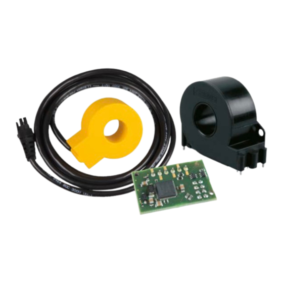
Seite 16: Ordering Information
Nachdruck und Vervielfältigung Reprinting and duplicating nur mit Genehmigung des Herausgebers. only with permission of the publisher. Bender GmbH & Co. KG Bender GmbH & Co. KG Postfach 1161 • 35301 Grünberg • Deutschland PO Box 1161 • 35301 Grünberg • Germany Londorfer Str.