Inhaltsverzeichnis
Werbung
Verfügbare Sprachen
Verfügbare Sprachen
Quicklinks
Werbung
Inhaltsverzeichnis

Verwandte Anleitungen für Fancom AT


Inhaltszusammenfassung für Fancom AT
- Seite 1 AT(M) MANUAL/HANDLEIDING/ANLEITUNG/NOTICE/MANUALE/ Руководство VERSION A1...
- Seite 2 N.B.: The original, authentic version of this manual is the English version produced by Fancom B.V. or one of its daughter companies (referred to further as Fancom). Any modifications introduced to this manual by third parties have neither been checked nor approved by Fancom. Modifications are taken by Fancom to include translations into languages other than English and the insertion and/or deletion of text and/or illustrations to/from the original contents.
- Seite 3 Table of contents General introduction ..........................1 How to use this manual ....................... 1 Symbols on the AT(M) ......................... 1 Fancom Sales & Service Center ....................1 Safety instructions and warnings ....................1 Installing the AT(M) ..........................3 Mount the AT(M) .......................... 3 Connect the AT(M) ........................
-
Seite 4: General Introduction
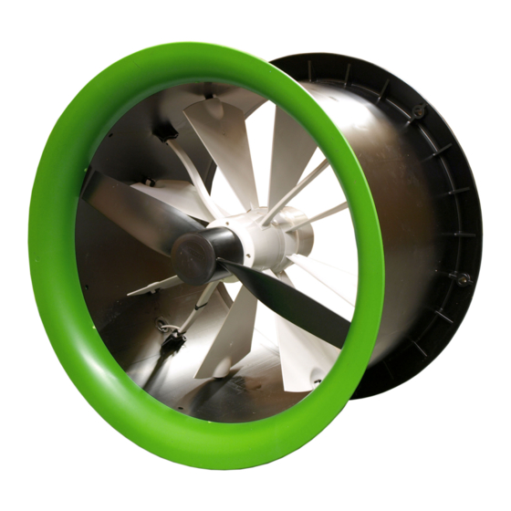
Moving parts can crush and cut. Air flow direction. Fancom Sales & Service Center For any questions and support, please contact the local Fancom Sales & Service Center. Safety instructions and warnings Before installing and commissioning the AT(M), carefully read the separate safety document. This... - Seite 5 Fancom and if the product's motor has been opened and changes have been made to the product. Never install a damaged AT(M). A damaged AT(M) is unsafe because it may fall apart. Which as a result can hurt humans and animals. Notify your supplier of any damages.
- Seite 6 3. Install the protective screen (see (p. 6)) If the AT(M) is installed at heights less than 2.5 m above the floor and/or the AT(M) is within reach of animals/humans then placement of a protective screen is necessary. Contact with rotating parts of the AT(M), can cause serious to fatal injuries as result.
- Seite 7 (M4 bolts spaced 120° from each other) in addition to the 3 standard linking pins. Install the protective screen If the AT(M) is installed at heights less than 2.5 m above the floor and/or the AT(M) is within reach of animals/humans then placement of a protective screen is necessary. Contact with rotating parts...
- Seite 8 If an end station controls more than one AT(M) unit (max. 3) in a parallel circuit, each AT(M) unit must be wired directly from the end station. Do not wire from a connection box of one AT(M) unit to a connection box of another AT(M) unit.
- Seite 9 Position feedback AT motor Cable 7×0.14mm2 shielded Trimming potentiometer max. stroke + s - Alignment lock Wiring connection Connection box Terminal strip 1 2 3 4 5 6 - s + (+) (-) Cable entry: Vortex damper ATM 7×0.8mm 24Vac control 4×0.8mm...
- Seite 10 Air inlet side Install the protective screen on the AT(M) and secure it as shown in the illustration below: Test the AT(M) 1. Check whether the AT(M) has been connected correctly. 2. Check whether the AT(M) works optimally. Do not touch any of the AT(M) moving parts.
-
Seite 11: First Use
20.000 ATM 80 15.000 ATM 63 10.000 5.000 1.000 1.200 1.400 First use Do not touch any of the AT(M) moving parts. Fancom advises to leave the AT(M) on for about 6 hours after installation, to let it run in. - Seite 12 This means the construction is not completely waterproof. Water in the AT(M) can cause mall funtions. Do not turn the AT(M) during or after the cleaning process. Note that the air inlet side is always on the bottom side.
- Seite 13 2. Place the entire AT(M) on the floor. 3. Unscrew the lid at the top and remove it. The AT motor and the DRS feedback sensor are now accessible. 4. Remove the AT motor, without disconnecting any connections. Position the motor so that the screw connection...
- Seite 14 8. Screw the lid on AT(M) (do not force it). 9. Reconnect the plug on the connection box. 10. Check if the system is functioning and re-adjust the AT control damper, if necessary. 11. Re-attach the AT(M) to the ventilation system.
-
Seite 15: Technical Specifications
Technical specifications Housing Protection class IP55 IP55 Operating environment Operating temperature range 0°C to +40°C Storage temperature range -10°C tot 50°C Relative humidity < 85%, not condensing... -
Seite 16: Ec Declaration Of Conformity
EC declaration of conformity Manufacturer: Fancom B.V. Address: Industrieterrein 34 City: Panningen (the Netherlands) Hereby declares that the: AT(M) Complies with the provisions of the: 1. Low voltage directive 2014/35/EU according to EN-EN-IEC 60335-1:2012 + AC:2014 + A11:2014 2. Machine directive 2006/42/EC 3. - Seite 17 N.B.: De originele, authentieke versie van deze handleiding is de door Fancom B.V. of door een van haar dochterondernemingen (verder aangeduid als Fancom) geproduceerde Engelstalige versie. Achteraf door derden aangebrachte wijzigingen in deze handleiding zijn door Fancom noch gecontroleerd, noch goedgekeurd.
- Seite 18 Inhoudsopgave Algemene inleiding ..........................1 Hoe gebruikt u deze handleiding ....................1 Symbolen op de AT(M) ........................ 1 Fancom Sales & Service Centre ....................1 Veiligheidsinstructies en -waarschuwingen .................. 1 De AT(M) installeren ..........................3 Monteer de AT(M) ........................3 Sluit de AT(M) aan ........................
-
Seite 19: Algemene Inleiding
Bewegende onderdelen kunnen verbrijzelen en snijden. Luchtstroomrichting. Fancom Sales & Service Centre Voor ondersteuning en antwoord op eventuele vragen kunt u het lokale Fancom Sales & Service Centre raadplegen. Veiligheidsinstructies en -waarschuwingen Lees het veiligheidsdocument aandachtig door, voordat u de AT(M) installeert en in gebruik neemt. - Seite 20 De garantie is niet van toepassing als het product op een andere wijze is geïnstalleerd dan door Fancom is aangegeven en/of als de motor van het product is geopend en er wijzigingen aan het product zijn aangebracht.
- Seite 21 2. Sluit de AT(M) aan (zie (p. 5)) 3. Plaats het beschermrooster (zie (p. 6)) Plaats een beschermrooster over de AT(M) als deze wordt geïnstalleerd op een hoogte van minder dan 2.5 m boven de vloer en/of binnen bereik van mens/dier. Contact met roterende onderdelen van de AT(M) kan ernstig of dodelijk letsel veroorzaken.
- Seite 22 3. Zet de koppelpennen vast door een schroef met sluitring vanuit de binnenkant van de koker in de koppelpennen te draaien. Boren Zet AT(M) 50 en 56 naast de 3 standaardkoppelpennen ook met 3 extra M4-bouten vast (120° t.o.v. elkaar) wanneer deze worden gebruikt in combinatie met verlengkokers CLICK. Plaats het beschermrooster Plaats een beschermrooster over de AT(M) als deze wordt geïnstalleerd op een hoogte van minder...
- Seite 23 Bedraad elke AT(M) rechtstreeks vanaf het eindstation als een eindstation meer dan één AT(M) regelt (max. 3) in een parallel circuit. Leg geen bedrading aan vanuit de aansluitkast van één AT(M) naar de aansluitkast van een andere AT(M).
- Seite 24 Positieterugmelder AT motor Kabel 7×0.14 mm² afgeschermd Afstelpotmeter max. slag + s - Positioneringsnok Draadbevestiging Aansluitbox Klemmenstrook 1 2 3 4 5 6 - s + (+) (-) Kabelinvoer: Smoorklep- ATM 7×0.8mm 24Vac sturing 4×0.8mm Richtingsgevoelige toerentalterugmelding - RTTM (alleen bij ATM) Plaats het beschermrooster (optie) Schakel de voedingsspanning uit vóór onderhoud of reiniging.
- Seite 25 Luchtinlaatzijde Plaats het beschermrooster op de AT(M) en zet het vast zoals getoond in de afbeelding hieronder: Test de AT(M) 1. Controleer of de AT(M) correct is aangesloten. 2. Controleer of de AT(M) optimaal werkt. Raak de bewegende onderdelen van de AT(M) niet aan.
-
Seite 26: Eerste Gebruik
De AT(M) gebruiken Voordat u de AT(M) kunt gebruiken, moet u de luchtstroommeting instellen in de regelcomputer. AT(M) 35-56 12.000 M3/h (cfm) 10.000 ATM 56 8.000 ATM 50 6.000 ATM 45 ATM 40 4.000 ATM 35 2.000 1.000 1.200 1.400 1.600... - Seite 27 Draai de AT(M) niet tijdens of na het schoonmaken. Zorg dat de luchtinlaat altijd naar beneden is gericht. Zorg dat de AT(M) na installatie altijd onder spanning blijft. Hierdoor wordt condensvorming in de AT(M) voorkomen. Afvoer/recycling Neem bij het afvoeren van de AT(M) alle relevante van toepassing zijnde wet- en regelgeving voor uw land in acht.
- Seite 28 3. Schroef het deksel aan de bovenkant los. Nu kunt u bij de AT-motor. 4. Koppel de bekabeling van de AT-motor los (let op de kleurvolgorde) en verwijder vervolgens de AT-motor. 5. Open de regelkleppen handmatig en controleer of deze soepel bewegen.
- Seite 29 8. Schroef het deksel op de AT(M) (niet forceren). 9. Sluit de stekker in de aansluitkast aan. 10. Controleer of het systeem werkt en stel de AT-regelklep indien noodzakelijk opnieuw af. 11. Bevestig de AT(M) weer op het ventilatiesysteem. Raadpleeg de volgende technische gegevens wanneer u de RTTM-sensor vervangt:...
-
Seite 30: Technische Gegevens
Technische gegevens Behuizing Beschermklasse IP55 IP55 Omgevingsklimaat Bereik bedrijfstemperatuur 0 °C tot +40 °C Bereik opslagtemperatuur -10 °C tot 50 °C Relatieve vochtigheid < 85%, niet condenserend... -
Seite 31: Eg-Verklaring Van Overeenstemming
EG-verklaring van overeenstemming Fabrikant: Fancom B.V. Adres: Industrieterrein 34 Plaats: Panningen (the Netherlands) Verklaart hiermee dat de: AT(M) Voldoet aan de bepalingen van de: 1. Laagspanningsrichtlijn 2014/35/EU conform EN-EN-IEC 60335-1:2012 + AC:2014 + A11:2014 2. Machinerichtlijn 2006/42/EG 3. EMC-richtlijn 2014/30/EU... - Seite 32 Service der zuständigen Fancom-Niederlassung auf. Sollten Sie ungeachtet der Sorgfalt, mit der die Anleitung verfasst worden ist, einen Fehler darin entdecken, bitten wir Sie, Fancom B.V. darüber schriftlich zu informieren. Fancom B.V., PO Box 7131, 5980 AC Panningen (The Netherlands).
- Seite 33 Inhalt Allgemeine Einleitung ..........................1 Zur Verwendung dieses Handbuchs .................... 1 Symbole auf dem AT(M) ......................1 Fancom Sales & Service Center ....................1 Sicherheitshinweise und Warnungen ................... 1 Installation des AT(M) ..........................3 Montage des AT(M) ........................3 Anschließen des AT(M) ....................... 5 Schutzgitter montieren (optional) ....................
-
Seite 34: Allgemeine Einleitung
Bewegliche Teile können zu Quetsch- und Schnittverletzungen führen. Luftstromrichtung. Fancom Sales & Service Center Wenden Sie sich bei Fragen und für Hilfe an das Fancom Sales & Service Center in Ihrer Nähe. Sicherheitshinweise und Warnungen Lesen Sie vor der Installation und Verwendung des AT(M) sorgfältig das separate Sicherheitsdokument. - Seite 35 Öffnen des Motors und am Produkt vorgenommenen Änderungen erlischt jeglicher Garantieanspruch. Es darf niemals ein beschädigter AT(M) installiert werden! Bei einem beschädigten AT(M) ist die Sicherheit nicht gewährleistet, da er auseinanderfallen kann! Dies kann zu Verletzungen von Menschen und Tieren führen. Benachrichtigen Sie Ihren Lieferanten über eventuelle Beschädigungen.
- Seite 36 2. Den AT(M) anschließen (siehe (s. 5)) 3. Schutzgitter montieren (siehe (s. 6)) Ist der AT(M) in einer Höhe von weniger als 2,5 m über dem Boden montiert bzw. befindet sich der AT(M) in Reichweite von Tieren/Menschen, muss ein Schutzgitter angebracht werden. Der Kontakt mit drehenden Teilen des AT(M) kann zu schweren bis tödlichen Verletzungen führen.
- Seite 37 Sicherungsstiften gesichert werden. Schutzgitter montieren Ist der AT(M) in einer Höhe von weniger als 2,5 m über dem Boden montiert bzw. befindet sich der AT(M) in Reichweite von Tieren/Menschen, muss ein Schutzgitter angebracht werden. Der Kontakt mit drehenden Teilen des AT(M) kann zu schweren bis tödlichen Verletzungen führen.
-
Seite 38: Anschließen Des At(M)
Anschlussdose einer AT(M)-Einheit zu der Anschlussdose einer anderen AT(M) Einheit her. Stellen Sie sicher, dass der AT(M) entsprechend den Vorschriften gut und sicher geerdet ist. Halten Sie die Signal- und Stromversorgungskabel so kurz wie möglich. Wenn die Länge des Kabels 40 m überschreitet, muss der 0V-Draht der 24-V-AC-Stromversorgung doppelt... -
Seite 39: Schutzgitter Montieren (Optional)
Positionsrückmelder AT motor Kabel 7×0.14 mm² abgeschirmt Einstellpotentiometer max. Hub. + s - Positionierungsnocke Drahtanschluss Klemmenleiste Anschlussdose 1 2 3 4 5 6 - s + (+) (-) Kabeleinfuhr: Regelklappe- ATM 7×0.8mm 24Vac steuerung 4×0.8mm Richtungsempfindliche Drehzahlrückmeldung - RDRM (ATM) Schutzgitter montieren (optional) Die Stromversorgung vor der Reinigung oder Wartung unterbrechen. - Seite 40 Zuluftseite Das Schutzgitter auf dem AT(M) montieren und gemäß der Darstellung in folgender Abbildung sichern: Testen des AT(M) 1. Überprüfen Sie, ob der AT(M) ordnungsgemäß angeschlossen ist. 2. Überprüfen Sie, ob der AT(M) optimal funktioniert. Berühren Sie keine beweglichen Teile des AT(M).
-
Seite 41: Verwendung Des At(M)
Verwendung des AT(M) Vor der Verwendung des AT(M) muss die Luftstrommessung im Regler eingestellt werden. AT(M) 35-56 12.000 M3/h (cfm) 10.000 ATM 56 8.000 ATM 50 6.000 ATM 45 ATM 40 4.000 ATM 35 2.000 1.000 1.200 1.400 1.600 1.800 AT(M) 63-80 25.000... -
Seite 42: Wartung
Fancom empfiehlt, den AT(M) für ca. 6 Stunden nach der Installation eingeschaltet zu lassen, damit er sich einlaufen kann. Wartung Für den AT(M) ist keine spezielle Wartung erforderlich. Fancom empfiehlt, die gesamte Klimaanlage, zu der diese AT(M) gehört, alle sechs Monate von einen Installateur auf korrekte Funktion überprüfen zu lassen. -
Seite 43: Austausch Des At-Motors
1. Den Stecker aus der Anschlussdose ziehen. 2. Den gesamten AT(M) auf dem Boden abstellen. 3. Den Verschluss an der Oberseite abschrauben und diesen entfernen. Der AT-Motor ist jetzt zugänglich. 4. Die Verkabelung vom AT-Motor abtrennen (hierbei auf die Farbreihenfolge achten) und anschließend den AT- Motor ausbauen. - Seite 44 RDRM-Sensor Magnet <1mm 6. Den AT-Motor wieder in Position bringen. Die Regeldrosselklappen müssen weiterhin geöffnet sein. 7. Den Verschluss wieder einsetzen, sodass die Anschlusszentrierung an der richtigen Position ist. 8. Den Verschluss an den AT(M) anschrauben (keine übermäßige Kraft anwenden).
-
Seite 45: Technische Daten
Technische Daten Gehäuse Schutzklasse IP55 IP55 Betriebsumgebung Betriebstemperaturbereich 0 bis +40°C Lagerungstemperaturbereich -10°C bis 50°C Relative Feuchte < 85 %, nicht kondensierend... -
Seite 46: Ec-Konformitätserklärung
EC-Konformitätserklärung Hersteller: Fancom B.V. Adresse: Industrieterrein 34 Ort: Panningen (The Netherlands) Erklärt hiermit, dass: AT(M) Die Bestimmungen erfüllt von: 1. Niederspannungsrichtlinie 2014/35/EU gemäß EN-EN-IEC 60335-1:2012 + AC:2014 + A11:2014 2. Maschinenrichtlinie 2006/42/EG 3. EMV-Richtlinie 2014/30/EU Emissionen gemäß NEN-EN-IEC 61000-6-3: 2007 Immunität gemäß... - Seite 47 N.B. : La version d’origine de ce manuel est en anglais et est publiée par Fancom B.V.. ou l’une de ses filiales (ci-après désignées par Fancom). En cas de modifications apportées à ce manuel par un tiers, elles ne sont ni vérifiées ni approuvées par Fancom.
- Seite 48 Première utilisation ........................8 Entretien ............................9 Mise au rebut / recyclage ......................9 Entretien ..............................10 Remplacement du moteur AT ....................10 Remplacement du capteur d’asservissement DRS ..............10 Spécifications techniques ........................12 Certificat de conformité CE ........................13...
-
Seite 49: Introduction Générale
Pour toute question ou demande d’assistance, veuillez contacter le SAV local de Fancom. Consignes de sécurité et avertissements Avant d’installer l’AT(M) et de le mettre en service, lisez attentivement le document supplémentaire relatif à la sécurité. Celui-ci contient des instructions, consignes et conditions. - Seite 50 La garantie n’est pas valable si le produit n’est pas installé conformément aux instructions de Fancom, que le moteur a été ouvert et que des modifications lui ont été apportées. N’installez jamais un AT(M) endommagé. Lorsqu’il est endommagé, l'AT(M) présente un danger parce qu'il peut tomber en morceaux.
- Seite 51 3. Installer la grille de protection (voir (p. 6)) Si l’AT(M) est installé à une hauteur de moins de 2,5 m au-dessus du sol et/ou que l’AT(M) se trouve à portée des animaux/humains alors l’installation d’une grille de protection est nécessaire.
- Seite 52 M4 (boulons M4 espacés de 120° les uns des autres) en plus des 3 goujons standard. Installer la grille de protection Si l’AT(M) est installé à une hauteur de moins de 2,5 m au-dessus du sol et/ou que l’AT(M) se trouve à portée des animaux/humains alors l’installation d’une grille de protection est nécessaire.
- Seite 53 Si un poste terminal commande plus d'une unité AT(M) (3 maxi) sur un circuit parallèle, chaque unité AT(M) doit être raccordée directement à partir du poste terminal. Ne branchez pas le boîtier de raccordement d’une unité AT(M) au boîtier de raccordement d’une autre unité AT(M).
- Seite 54 Rétroaction de la position Moteur AT Câble blindé 7×0.14mm² Potentiomètre de réglage course maxi. + s - Détrompeur Fixation de fils Boîtier de raccordement Bornier 1 2 3 4 5 6 - s + (+) (-) Entrée de câble: Réglage de ATM 7×0.8mm...
- Seite 55 Côté admission d’air Installez la grille de protection sur l’AT(M) et fixez-la comme sur l’illustration ci-dessous : Tester l’AT(M) 1. Vérifiez que l’AT(M) a été branché correctement. 2. Vérifiez que l’AT(M) fonctionne correctement. Ne touchez aucune partie mobile de l'AT(M).
-
Seite 56: Première Utilisation
1.800 AT(M) 63-80 25.000 M3/h (cfm) 20.000 ATM 80 15.000 ATM 63 10.000 5.000 1.000 1.200 1.400 Première utilisation Ne touchez aucune partie mobile de l'AT(M). Fancom vous conseille de laisser l’AT(M) sous tension pendant 6 heures environ après l’installation. -
Seite 57: Mise Au Rebut / Recyclage
3.2.1 Nettoyage Il est possible de nettoyer l’AT(M) à l’eau, mais vous devez tenir compte des consignes suivantes : N’utilisez PAS de flexible à haute pression et ne le dirigez pas vers les joints ou les ouvertures à faible distance. - Seite 58 Remplacement du capteur d’asservissement DRS Assurez que le contrôle est de 100 %. Le registre de commande AT doit s’ouvrir entièrement. La tension de sortie doit également être de 0 Vcc. En cas d’ouverture complète du registre de commande AT, procédez comme suit.
- Seite 59 8. Vissez le couvercle AT(M) (ne forcez pas). 9. Reconnectez la fiche au boîtier de raccordement. 10. Assurez-vous que le système fonctionne et si nécessaire, réajustez le registre de commande AT. 11. Fixez le AT(M) au système de ventilation. Reportez-vous aux spécifications techniques lors du remplacement du capteur d’asservissement DRS : Capteur d’asservissement DSR...
-
Seite 60: Spécifications Techniques
Spécifications techniques Boîtier Classe de protection IP55 IP55 Environnement de fonctionnement Températures de fonctionnement 0 °C à +40 °C Températures de stockage -10 à 50 °C Humidité relative < 85 %, sans condensation... -
Seite 61: Certificat De Conformité Ce
Fabricant : Fancom B.V. Adresse : Industrieterrein 34 Ville : Panningen (The Netherlands) Certifie par la présente que le : AT(M) est conforme aux dispositions suivantes : 1. Directive sur les basses tensions 2014/35/EU conformément à la norme EN-EN-IEC 60335-1:2012 + AC:2014 + A11:2014 2. - Seite 62 Fancom B.V. o da una delle sue società controllate (di seguito denominate Fancom). Qualsiasi modifica apportata al presente manuale da terzi non è né controllata né approvata da Fancom. Con modifiche Fancom intende tra le altre cose la traduzione in una lingua diversa da quella inglese e l'aggiunta e/o l'eliminazione di testo e/ o figure dal contenuto originale.
- Seite 63 Indice Introduzione generale ..........................1 Come utilizzare il manuale ......................1 I simboli su AT(M) ........................1 Centro vendite e supporto Fancom ..................... 1 Istruzioni ed avvertenze di sicurezza ..................1 Installazione di AT(M) ..........................3 Montare AT(M) ..........................3 Collegare AT(M) ...........................
-
Seite 64: Introduzione Generale
Direzione del flusso d’aria. Centro vendite e supporto Fancom Per eventuali domande o supporto si prega di contattare il Centro Vendite & Supporto Fancom di zona. Istruzioni ed avvertenze di sicurezza Prima di installare e mettere in servizio AT(M), leggere con attenzione il documento separato relativo alla sicurezza. - Seite 65 La garanzia non si applica se il prodotto viene installato in qualsiasi modo difforme da quanto indicato da Fancom e se il motore del prodotto è stato aperto e sono state apportate modifiche al prodotto.
- Seite 66 3. Installare la griglia di protezione (vedi (p. 6)) Se AT(M) è installato ad un'altezza inferiore a 2,5 m dal pavimento e/o se AT(M) è alla portata di animali e/o persone, è necessario installare una schermatura protettiva. Il contatto con le parti rotanti di AT(M) può...
- Seite 67 3 perni di collegamento standard. Installare la griglia di protezione Se AT(M) è installato ad un'altezza inferiore a 2,5 m dal pavimento e/o se AT(M) è alla portata di animali e/o persone, è necessario installare una schermatura protettiva. Il contatto con le parti...
- Seite 68 Prima di collegare, interrompere l'alimentazione e riaccendere solo dopo aver approntato l'intera installazione. Se una stazione finale controlla più AT(M) (max. 3) collegati in parallelo, ciascun AT(M) deve essere cablato direttamente sulla stazione finale. Non collegare tra loro le scatole di giunzione di due AT(M).
- Seite 69 Retroazione della posizione Motore AT Cavo 7×0.14mm² schermato Potenziometro d'aggiustamento, Corsa massima + s - Perno guida Fissaggio del filo Scatola di giunzione Morsettiera 1 2 3 4 5 6 - s + (+) (-) Pressacavo: Comando ATM 7×0.8mm 24Vac otturatore 4×0.8mm...
- Seite 70 Lato ingresso aria Posizionare la griglia di protezione su AT(M) e fissarla come mostrato nell’illustrazione seguente: Collaudare AT(M) 1. Controllare se AT(M) è stato collegato correttamente. 2. Controllare se AT(M) funziona in modo ottimale. Non toccare parti in movimento di AT(M).
-
Seite 71: Primo Utilizzo
Utilizzo del AT(M) Prima di utilizzare il AT(M) è necessario impostare la misurazione del flusso d’aria nella centralina. AT(M) 35-56 12.000 M3/h (cfm) 10.000 ATM 56 8.000 ATM 50 6.000 ATM 45 ATM 40 4.000 ATM 35 2.000 1.000 1.200 1.400... - Seite 72 Fancom raccomanda di lasciare AT(M) acceso per circa 6 ore dopo l’installazione, per svolgere il corretto rodaggio. Manutenzione AT(M) non necessita di manutenzione specifica. Fancom consiglia ispezioni semestrali svolte dal proprio tecnico installatore sull’intero sistema di climatizzazione, di cui AT(M) fa parte.
- Seite 73 Verificare la presenza di un controllo al 100%, l’otturatore del controllo AT deve essere completamente aperto. Anche la tensione in uscita deve essere a 0 V CC. Se l’otturatore di controllo AT è completamente aperto, procedere come indicato di seguito.
- Seite 74 8. Avvitare il coperchio sul AT(M) (senza forzare). 9. Ricollegare lo spinotto alla scatola di giunzione. 10. Controllare il corretto funzionamento del sistema e regolare nuovamente l’otturatore di controllo AT, se necessario. 11. Ricollegare il AT(M) al sistema di ventilazione.
-
Seite 75: Specifiche Tecniche
Specifiche tecniche Custodia Classe di protezione IP55 IP55 Ambiente operativo Intervallo della temperatura di esercizio da 0 °C a +40 °C Intervallo della temperatura di stoccaggio da -10 °C a 50 °C Umidità relativa < 85%, non condensante... -
Seite 76: Dichiarazione Di Conformità Ce
Dichiarazione di conformità CE Il produttore: Fancom B.V. Indirizzo: Industrieterrein 34 Località: Panningen (the Netherlands) Con la presente dichiara che: AT(M) È conforme alle disposizioni della: 1. Direttiva bassa tensione 2014/35/UE secondo EN-EN-IEC 60335-1:2012 + AC:2014 + A11:2014 2. Direttiva macchine 2006/42/CE 3. - Seite 77 технического обслуживания компании Fancom. Если, несмотря на приложенные при составлении этого руководства усилия, вы обнаружите в нем какие-либо ошибки, сообщите об этом в компанию Fancom B.V. в письменном виде. Fancom B.V., PO Box 7131, 5980 AC Паннинген (Panningen) Нидерланды (The Netherlands).
- Seite 78 Содержание Общее введение ............................1 Принципы работы с этим руководством .................. 1 Обозначения на изделии AT(M) ....................1 Fancom Центр продаж и обслуживания ................... 1 Правила техники безопасности и предупреждения ..............1 Монтаж AT(M) ............................3 Установка AT(M) ......................... 3 Подключение...
-
Seite 79: Общее Введение
Подвижные части могут нанести травмы (например, переломы или порезы). Направление потока воздуха. Fancom Центр продаж и обслуживания По всем вопросам и за помощью обращайтесь в региональный центр продаж и обслуживания Fancom. Правила техники безопасности и предупреждения Перед выполнением работ по монтажу и пусконаладке AT(M) внимательно ознакомьтесь... - Seite 80 квалифицированных монтажников электротехнического оборудования (в соответствии с действующими стандартами). При нарушении инструкций компании Fancom по монтажу изделия, а также в случае внесения изменений в его конструкцию либо вскрытия двигателя гарантия аннулируется. Запрещается устанавливать изделие AT(M) с повреждениями. Поврежденное изделие AT(M) небезопасно, так...
- Seite 81 2. Подсоедините AT(M) (см. (с. 5)). 3. Установите защитный экран (см. (с. 6)). При монтаже AT(M) на высоте менее 2,5 м или в пределах досягаемости людей или животных необходимо использовать защитный экран. Прикосновение к вращающимся элементам AT(M) может привести к тяжелым увечьям или смерти.
- Seite 82 штифтов). При этом угол между любыми двумя болтами M4 должен быть равен 120°. Установка защитного экрана При монтаже AT(M) на высоте менее 2,5 м или в пределах досягаемости людей или животных необходимо использовать защитный экран. Прикосновение к вращающимся элементам AT(M) может привести к тяжелым увечьям или смерти.
- Seite 83 Перед подсоединением изделия выключите электропитание и включите его снова только после полного завершения установки. Если рабочая станция управляет более чем одним блоком AT(M) (до трех) в параллельной цепи, необходимо подсоединить каждый блок AT(M) непосредственно к рабочей станции. Не подсоединяйте распределительную коробку одного блока AT(M) к распределительной...
- Seite 84 Местоположение обратной связи Электродвигатель АТ Экранированный кабель 7×0.14mm² Потенциометр регулировки максимального хода + s - Установочный фиксатор Проводное соединение Соединительная коробка 1 2 3 4 5 6 Клеммная колодка - s + (+) (-) Кабельный ввод: Управление ATM 7×0.8mm 24Vac вихревой...
- Seite 85 Сторона впуска воздуховода Установите защитный экран на изделие AT(M) и закрепите его, как показано на рисунке ниже. Проверка работы AT(M) 1. Проверьте правильность подключения AT(M). 2. Убедитесь в том, что AT(M) работает оптимальным образом. Не прикасайтесь к движущимся частям изделия AT(M).
-
Seite 86: Первое Использование
Эксплуатация AT(M) Перед началом эксплуатации AT(M) необходимо настроить измерение расхода в контроллере. AT(M) 35–56 12.000 M3/h (cfm) 10.000 ATM 56 8.000 ATM 50 6.000 ATM 45 ATM 40 4.000 ATM 35 2.000 1.000 1.200 1.400 1.600 1.800 AT(M) 63–80 25.000... -
Seite 87: Техническое Обслуживание
дроссельные заслонки. Это означает, что конструкция не является полностью влагозащищенной. Попадание воды в изделие AT(M) может привести к неисправностям. Не поворачивайте изделие AT(M) во время или после очистки. Обратите внимание на то, что сторона с впускным воздуховодом всегда должна быть расположена снизу. - Seite 88 1. Отсоедините штекер от распределительной коробки. 2. Расположите устройство AT(M) на полу. 3. Отвинтите верхнюю крышку и снимите ее. В результате откроется доступ к двигателю AT и датчику обратной связи. 4. Извлеките двигатель AT, не отсоединяя его. Расположите двигатель таким образом, чтобы получить...
- Seite 89 вращения магнит <1mm 6. Установите на место двигатель AT. Регулирующие клапаны должны быть по-прежнему открыты. 7. Установите на место крышку; обратите внимание на расположение фиксатора. 8. Закрутите крышку на изделии AT(M) (не применяйте избыточную силу). 9. Подсоедините штекер к распределительной коробке.
-
Seite 90: Технические Характеристики
Технические характеристики Корпус Класс защиты IP55 IP55 Условия эксплуатации Диапазон рабочих температур От 0 до 40 °C Диапазон температуры хранения От -10 до 50 °C Относительная влажность < 85 % без конденсации 12 ... -
Seite 91: Декларация Соответствия Ес
Декларация соответствия ЕС Изготовитель: Fancom B.V. Адрес: Industrieterrein 34 Город: Паннинген (Panningen) Нидерланды (The Netherlands) Настоящим изготовитель гарантирует, что изделие AT(M) соответствует положениям следующих документов: 1. Директива 2014/35/ЕС о низковольтном оборудовании Стандарт NEN-EN-IEC 60335-1:2012, включая дополнения AC:2014 и A11:2014 2. Директива 2006/42/EC о безопасности машин и оборудования...