Herunterladen Inhalt Inhalt Diese Seite drucken

WIKA TR31-3 Betriebsanleitung

Oem-miniatur-widerstandsthermometer
Vorschau ausblenden Andere Handbücher für TR31-3:
Inhaltsverzeichnis

Werbung

Verfügbare Sprachen

Verfügbare Sprachen

OEM miniature resistance thermometer
Models TR31-3, TR31-K
OEM-Miniatur-Widerstandsthermometer
Typen TR31-3, TR31-K
Sonde à résistance miniature OEM
Types TR31-3, TR31-K
Termorresistencia miniatura OEM
Modelo TR31-3, TR31-K
70018194
Model TR31-3
Operating instructions
Betriebsanleitung
Mode d'emploi
Manual de instrucciones
Model TR31-K
EN
DE
FR
ES

Werbung

Inhaltsverzeichnis
loading

Inhaltszusammenfassung für WIKA TR31-3

  • Seite 1 Operating instructions Betriebsanleitung Mode d’emploi Manual de instrucciones OEM miniature resistance thermometer Models TR31-3, TR31-K OEM-Miniatur-Widerstandsthermometer Typen TR31-3, TR31-K Sonde à résistance miniature OEM Types TR31-3, TR31-K Termorresistencia miniatura OEM Modelo TR31-3, TR31-K 70018194 Model TR31-3 Model TR31-K...
  • Seite 2 Mode d'emploi type TR31 Page 71 - 104 Manual de instrucciones modelo TR31 Página 105 - 138 © 07/2014 WIKA Alexander Wiegand SE & Co. KG All rights reserved. / Alle Rechte vorbehalten. WIKA ® is a registered trademark in various countries.
  • Seite 3: Inhaltsverzeichnis

    5. Commissioning, operation 6. Configuration 7. Configuration software WIKAsoft-TT 8. Connecting PU-548 programming unit 9. Faults 10. Maintenance and cleaning 11. Dismounting, return and disposal 12. Specifications Appendix: CSA control drawing Declarations of conformity can be found online at www.wika.com. WIKA operating instructions models TR31-3, TR31-K...
  • Seite 4: General Information

    (IP67 or IP69K). The vibration resistance conforms to IEC 60751 (20 g, dependent on the instrument version). The impact resistance of all versions meets the requirements of IEC 60751. WIKA operating instructions models TR31-3, TR31-K...
  • Seite 5 [ 0,748 inch] [ 0,748 inch] [ 0,748 inch] [ 0,748 inch] SW22/27 SW22/27 SW22/27 SW22/27 Hex22/27 Hex22/27 Hex22/27 Hex22/27 14069565.05 14069565.05 140695 REVISION WIKA operating instructions models TR31-3, TR31-K KLI-ZCHG TR33/34 KLI-ZCHG TR33/34 KLI-ZCHG TR33/34 KLI-ZCHG TR33/34 drawing number...
  • Seite 6 ALEXANDER WIEGAND SE & Co. KG SIZE ISO 14405 >6 >30 >120 ISO 1302 ...6 ...30 ...120 ...400 D-63911 Klingenberg language ISO 8015 [inch] ± ± ± ± www.wika.com R in µm GER/ENG DEKLI1_EN_A3M_T01 13.02.2020 WIKA operating instructions models TR31-3, TR31-K...
  • Seite 7 R in µm R in µm GER/ENG GER/ENG Length of the free stranded wires DEKLI1_EN_A3M_T01 13.02.2020 DEKLI1_EN_A3M_T01 13 Height process connection 1/4 NPT = 15 mm [0.59 in] 1/2 NPT = 19 mm [0.75 in] WIKA operating instructions models TR31-3, TR31-K...
  • Seite 8: Scope Of Delivery

    [-58 ... +302 °F] (without neck tube) and -50 … +250 °C [-58 ... +482 °F] (with neck tube) in liquid and gaseous media. The version with mineral- insulated sheathed cable and neck tube allows to measure temperatures WIKA operating instructions models TR31-3, TR31-K...
  • Seite 9: Responsibility Of The Operator

    Improper handling or operation of the instrument outside of its technical specifications requires the instrument to be taken out of service immediately and inspected by an authorised WIKA service engineer. The manufacturer shall not be liable for claims of any type based on operation contrary to the intended use.
  • Seite 10: Personnel Qualification

    The skilled electrical personnel must comply with current legal accident prevention regulations. Special operating conditions require further appropriate knowledge, e.g. of aggressive media. WIKA operating instructions models TR31-3, TR31-K...
  • Seite 11: Labelling, Safety Marks

    Thermometer with transmitter and 4 ... 20 mA output signal ■ Thermometer with direct sensor output with Pt100 and Pt1000 ■ Serial number, TAG no.  Before mounting and commissioning the instrument, ensure you read the operating instructions! WIKA operating instructions models TR31-3, TR31-K...
  • Seite 12: Transport, Packaging And Storage

    Humidity: 5 ... 95 % r. h. ■ Avoid exposure to the following factors: Direct sunlight or proximity to hot objects ■ Mechanical vibration, mechanical shock (putting it down hard) ■ Soot, vapour, dust and corrosive gases ■ Potentially explosive environments, flammable atmospheres ■ WIKA operating instructions models TR31-3, TR31-K...
  • Seite 13: Commissioning, Operation

    The insertion length, along with the flow velocity and viscosity of the process media, may reduce the max. loading on the thermowell. The housing must be grounded against electromagnetic fields and electrostatic discharge. It is not necessary to connect the housing WIKA operating instructions models TR31-3, TR31-K...
  • Seite 14: Installation Examples

    Insertion length A Installation on pipes a on elbows b in smaller pipe, inclined c perpendicular to flow direction For information on tapped holes, refer to DIN 3852 or for NPT threads to ANSI B 1.20. WIKA operating instructions models TR31-3, TR31-K...
  • Seite 15: Electrical Connection

    ■ M12 x 1 circular connector (4-pin) Directly connected cable 2-wire white 3-wire white 4-wire white white 4 ... 20 mA Alternative pin assignments possible. For further information see order documentation. Accessories: M12 x 1 Pt adapter to DIN EN 175301-803 angular connector M12 x 1 connector Angular connector WIKA operating instructions models TR31-3, TR31-K...
  • Seite 16 Alternative pin assignments possible. For further information see order documentation. Accessories: M12 x 1 transmitter adapter to DIN EN 175301-803 angular connector M12 x 1 connector Angular connector 4 ... 20 mA Pin assignment angular connector Signal Description 10 ... 30 V not connected not connected WIKA operating instructions models TR31-3, TR31-K...
  • Seite 17: Load Diagram

    PU-548, a max. load of 350 Ω is admissible. ≤ (U - 10 V) / 23 mA with R in Ω and U in V 1083 Voltage U in V WIKA operating instructions models TR31-3, TR31-K...
  • Seite 18: Configuration

    PU-548 programming unit (accessories, order no. 14231581). The connection with the thermometer is made via the appropriate adapter cable. Accessories, M12 x 1 circular connector: order number 14003193 ■ Accessories, crocodile clips for bare-end connecting wires: ■ order number 14097967 WIKA operating instructions models TR31-3, TR31-K...
  • Seite 19 Without neck tube -50 ... +150 °C [-58 ... +302 °F] With neck tube -50 ... +250 °C [-58 ... +482 °F] 1) Version with mineral-insulated sheathed cable can be used up to 300 °C [572 °F]. WIKA operating instructions models TR31-3, TR31-K...
  • Seite 20: Configuration Software Wikasoft-Tt

    The selection of the COM port is made automatically. After the connection of a transmitter (using the PU-548), on pressing the “Start” button, the configuration interface is loaded. The configuration interface can only be loaded when an instrument is connected. WIKA operating instructions models TR31-3, TR31-K...
  • Seite 21: Configuration Procedure

    All subsequent instruments ■ 1. “Loading the instrument data” 2. [optional] Cancel write protection 3. [optional] Change the required parameters, e. g. TAG number 4. “Save to the instrument” 5. [optional] Activate write protection WIKA operating instructions models TR31-3, TR31-K...
  • Seite 22: Connecting Pu-548 Programming Unit

    For further information, see chapter 1 “General information”, “Contact data” or the back page of these operating instructions. 8. Connecting PU-548 programming unit Connection PU-548 ↔ adapter cable with M12 connector TR31-3 (predecessor, programming unit model PU-448, also compatible) WIKA operating instructions models TR31-3, TR31-K...
  • Seite 23: Faults

    ▶ Ensure that pressure or signal is no longer present and protect against accidental commissioning. ▶ Contact the manufacturer. ▶ If a return is needed, please follow the instructions given in chapter 11.2 “Return”. WIKA operating instructions models TR31-3, TR31-K...
  • Seite 24 Deposits on the Remove deposits thermowell WIKA operating instructions models TR31-3, TR31-K...
  • Seite 25: Maintenance And Cleaning

    For contact details see chapter 1 “General information” or the back page of the operating instructions. 10.1 Maintenance The resistance thermometers described here require absolutely no maintenance and contain no components which could be repaired or replaced. WIKA operating instructions models TR31-3, TR31-K...
  • Seite 26 Do not use any aggressive cleaning agents. ▶ Do not use any hard or pointed objects for cleaning. ▶ Wash or clean the dismounted instrument, in order to protect persons and the environment from exposure to residual media. WIKA operating instructions models TR31-3, TR31-K...
  • Seite 27: Dismounting, Return And Disposal

    Let the instrument cool down sufficiently before dismounting it! 11.2 Return Strictly observe the following when shipping the instrument: All instruments delivered to WIKA must be free from any kind of hazardous substances (acids, bases, solutions, etc.). When returning the instrument, use the original packaging or a suitable transport package.
  • Seite 28 Dispose of instrument components and packaging materials in an environmentally compatible way and in accordance with the country- specific waste disposal regulations. Do not dispose of with household waste. Ensure a proper disposal in accordance with national regulations. WIKA operating instructions models TR31-3, TR31-K...
  • Seite 29: Specifications

    Total measuring deviation per IEC 62828 element + transmitter Influence of ambient temperature 0.1 % of the set measuring span / 10 K T Influence of supply voltage ±0.025 % / V (depending on the supply voltage U Influence of load ±0.05 % / 100 Ω WIKA operating instructions models TR31-3, TR31-K...
  • Seite 30 (0.35 K² + 0.25 K² + 0.15 K² + 0.15 K² + 0.15 K²+ 0.15 K²) sqrt (0.275 K²) = 0.524 K Measuring deviation (maximum) 0.35 K + 0.25 K + 0.15 K + 0.15 K + 0.15 K + 0.15 K = 1.2 K WIKA operating instructions models TR31-3, TR31-K...
  • Seite 31: Measuring Range

    G ½ B ■ ¼ NPT ■ ½ NPT ■ M12 x 1.5 ■ M20 x 1.5 ■ 7/16-20 UNF-2A ■ Protection tube Protection tube diameter 3 mm [0.12 in] ■ 6 mm [0.24 in] ■ WIKA operating instructions models TR31-3, TR31-K...
  • Seite 32 ≤ 3.6 mA Communication Info data TAG no., description and user message can be stored in transmitter Configuration and Permanently stored calibration data Configuration software WIKAsoft-TT → Configuration software (multilingual) as a download from www.wika.com WIKA operating instructions models TR31-3, TR31-K...
  • Seite 33: Operating Conditions

    After approx. 4 minutes, the instrument will function to the specifications (accuracy) given in the data sheet. Operating conditions Ambient temperature range M12 x 1 circular connector (model TR31-3-x-xx) 4 ... 20 mA version -40 ... +85 °C [-40 ... +185 °F] Version with FKM O-ring: -20 °C [-4 °F] Pt100 / Pt1000 version -50 ...
  • Seite 34 1) Dependent on the instrument version 2) Reduced operating pressure when using a compression fitting: Stainless steel = max. 100 bar [1,450 psi] / PTFE = max. 8 bar [116 psi] 3) Not tested with UL WIKA operating instructions models TR31-3, TR31-K...
  • Seite 35 12. Specifications Patents/property rights No. 001370985 M12 x 1 adapter to angular connector DIN EN 175301-803 → For further specifications see WIKA data sheet TE 60.31 and the order documentation. WIKA operating instructions models TR31-3, TR31-K...
  • Seite 36: Appendix: Csa Control Drawing

    Appendix: CSA control drawing WIKA operating instructions models TR31-3, TR31-K...
  • Seite 37 4. Transport, Verpackung und Lagerung 5. Inbetriebnahme, Betrieb 6. Konfiguration 7. Konfigurationssoftware WIKAsoft-TT 8. Programmiereinheit PU-548 anschließen 9. Störungen 10. Wartung und Reinigung 11. Demontage, Rücksendung und Entsorgung 12. Technische Daten Anlage: CSA control drawing Konformitätserklärungen finden Sie online unter www.wika.de. WIKA-Betriebsanleitung Typen TR31-3, TR31-K...
  • Seite 38: Allgemeines

    Es ist stoß- und vibrationsfest aufgebaut und alle elektrischen Bauteile sind gegen Feuchtigkeit geschützt (IP67 bzw. IP69K). Die Vibrationsbeständigkeit entspricht der IEC 60751 (20 g, abhängig von der Geräteausführung). Die Stoßfestigkeit entspricht für alle Versionen den Anforderungen der IEC 60751. WIKA-Betriebsanleitung Typen TR31-3, TR31-K...
  • Seite 39: Prozessanschluss Mit Zylindrischem Gewinde (Bzw. Ohne Prozessanschluss)

    M12x1 M12x1 M12x1 M12x1 19 mm 19 mm 19 mm 19 mm [ 0,748 inch] [ 0,748 inch] [ 0,748 inch] [ 0,748 inch] SW22/27 SW22/27 SW22/27 SW22/27 Hex22/27 Hex22/27 Hex22/27 Hex22/27 14069565.05 14069565.05 140695 WIKA-Betriebsanleitung Typen TR31-3, TR31-K REVISION...
  • Seite 40 ALEXANDER WIEGAND SE & Co. KG SIZE ISO 14405 >6 >30 >120 ISO 1302 ...6 ...30 ...120 ...400 D-63911 Klingenberg language ISO 8015 [inch] ± ± ± ± www.wika.com R in µm GER/ENG DEKLI1_EN_A3M_T01 13.02.2020 WIKA-Betriebsanleitung Typen TR31-3, TR31-K...
  • Seite 41: Prozessanschluss Mit Kegeligem Gewinde

    ± ± ± ± R in µm R in µm GER/ENG GER/ENG Länge der freien Litzen DEKLI1_EN_A3M_T01 13.02.2020 DEKLI1_EN_A3M_T01 13 Höhe Prozessanschluss 1/4 NPT = 15 mm [0,59 in] 1/2 NPT = 19 mm [0,75 in] WIKA-Betriebsanleitung Typen TR31-3, TR31-K...
  • Seite 42: Lieferumfang

    Das Widerstandsthermometer Typ TR31 wird als universelles Thermometer zum Messen von Temperaturen von -50 ... +150 °C [-58 ... +302 °F] (ohne Halsrohr) und -50 ... +250 °C [-58 ... +482 °F] (mit Halsrohr) in flüssigen und gasförmigen Medien verwendet. Die Ausfüh- WIKA-Betriebsanleitung Typen TR31-3, TR31-K...
  • Seite 43 Die Verantwortung für die Auswahl des Thermometers bzw. mehrteiligen Schutzrohres, sowie für deren Werkstoffauswahl zur Gewährleistung einer sicheren Funktion in der Anlage bzw. Maschine obliegt dem Betrei- ber. WIKA kann während der Angebotserstellung lediglich Empfehlungen aussprechen, die sich an unseren Erfahrungen in ähnlichen Applikatio- nen orientieren.
  • Seite 44: Personalqualifikation

    Normen und Bestimmungen. Das Elektrofachpersonal muss die Bestimmungen der geltenden gesetzlichen Vorschriften zur Unfallverhütung erfüllen. Spezielle Einsatzbedingungen verlangen weiteres entsprechendes Wissen, z. B. über aggressive Medien. WIKA-Betriebsanleitung Typen TR31-3, TR31-K...
  • Seite 45: Beschilderung, Sicherheitskennzeichnungen

    Angaben zur Ausführung (Messelement, Ausgangssignal, Messbereich...)  Thermometer mit Messumformer und Ausgangssignal 4 … 20 mA ■ Thermometer mit direktem Sensorausgang mit Pt100 und Pt1000 ■ Seriennummer, TAG-Nummer  Vor Montage und Inbetriebnahme des Gerätes unbedingt die Betriebsanleitung lesen! WIKA-Betriebsanleitung Typen TR31-3, TR31-K...
  • Seite 46: Transport, Verpackung Und Lagerung

    Feuchtigkeit: 5 ... 95 % r. F. ■ Folgende Einflüsse vermeiden: Direktes Sonnenlicht oder Nähe zu heißen Gegenständen ■ Mechanische Vibration, mechanischer Schock (hartes Aufstellen) ■ Ruß, Dampf, Staub und korrosive Gase ■ Explosionsgefährdete Umgebung, entzündliche Atmosphären ■ WIKA-Betriebsanleitung Typen TR31-3, TR31-K...
  • Seite 47: Inbetriebnahme, Betrieb

    Viskosität des Prozessmediums können sich reduzierend auf die max. Schutzrohrbelastung auswirken. Das Gehäuse muss gegen elektromagnetische Felder und elektrosta- tische Aufladungen geerdet werden. Es muss nicht gesondert an das Potentialausgleichsystem angeschlossen werden, wenn es festen und WIKA-Betriebsanleitung Typen TR31-3, TR31-K...
  • Seite 48: Einbaubeispiele

    Erlöschung der Garantie. Einbaubeispiele Einbaulänge A Installation an Rohren a am Winkelstück b in kleinerem Rohr, geneigt c senkrecht zur Strömungsrichtung Angaben zu den Einschraublöchern der DIN 3852 bzw. für NPT-Gewinde der ANSI B 1.20 entnehmen. WIKA-Betriebsanleitung Typen TR31-3, TR31-K...
  • Seite 49: Anzugsdrehmomente Für Klemmverschraubungen

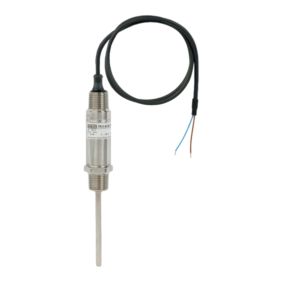
    Der elektrische Anschluss erfolgt über den Rundstecker. Ausgangssignal Pt100 und Pt1000 (Standard) ■ Rundstecker M12 x 1 (4-polig) Direkt angeschlossenes Kabel 2-Leiter weiß 3-Leiter weiß 4-Leiter weiß weiß 4 ... 20 mA Alternative Anschlussbelegungen möglich. Weitere Informationen siehe Bestellunterlagen. Zubehör: Pt-Adapter M12 x 1 zu Winkelstecker DIN EN 175301-803 M12 x 1-Stecker Winkelstecker WIKA-Betriebsanleitung Typen TR31-3, TR31-K...
  • Seite 50: Pin Signal Beschreibung

    10 ... 30 V Braun 10 ... 30 V nicht angeschlossen Blau nicht angeschlossen Alternative Anschlussbelegungen möglich. Weitere Informationen siehe Bestellunterlagen. Zubehör: Transmitter-Adapter M12 x 1 zu Winkelstecker DIN EN 175301-803 M12 x 1-Stecker Winkelstecker 4 ... 20 mA Anschlussbelegung Winkelstecker Signal Beschreibung 10 ... 30 V nicht angeschlossen nicht angeschlossen WIKA-Betriebsanleitung Typen TR31-3, TR31-K...
  • Seite 51: Alternativ Für Nordamerika

    Bei Kommunikation mit dem Gerät, mit Programmiereinheit PU-548, ist eine Bürde von maximal 350 Ω zulässig. ≤ (U - 10 V) / 23 mA mit R in Ω und U in V 1083 Spannung U in V WIKA-Betriebsanleitung Typen TR31-3, TR31-K...
  • Seite 52: Verhalten Des Elektrischen Ausgangssignals 4

    Das Konfigurieren erfolgt über die USB-Schnittstelle eines PC‘s via Programmiereinheit PU-548 (Zubehör, Bestell-Nr. 14231581). Mittels passendem Adapterkabel wird die Verbindung zum Thermometer herge- stellt. Zubehör, M12 x 1-Rundstecker: Bestellnummer 14003193 ■ Zubehör, Krokodilklemmen für lose Anschlussdrähte: ■ Bestellnummer 14097967 WIKA-Betriebsanleitung Typen TR31-3, TR31-K...
  • Seite 53 Mit Halsrohr -30 ... +250 °C [-22 ... +482 °F] Klasse B: ■ Ohne Halsrohr -50 ... +150 °C [-58 ... +302 °F] Mit Halsrohr -50 ... +250 °C [-58 ... +482 °F] 1) Ausführung mit mineralisolierter Mantelleitung einsetzbar bis 300 °C [572 °F]. WIKA-Betriebsanleitung Typen TR31-3, TR31-K...
  • Seite 54: Konfigurationssoftware Wikasoft-Tt

    Länderflagge geändert werden. Die Auswahl des COM-Ports erfolgt automatisch. Nach dem Anschluss eines Transmitters (mit PU-548) kann durch Aktivieren des Start-Buttons die Konfigurationsoberfläche geladen werden. Die Konfigurationsoberfläche kann nur mit einem angeschlossenen Gerät geladen werden. WIKA-Betriebsanleitung Typen TR31-3, TR31-K...
  • Seite 55: Fehlerdiagnose

    4. “In das Gerät speichern” 5. [optional] Schreibschutz aktivieren Alle folgenden Geräte ■ 1. “Gerätedaten laden” 2. [optional] Schreibschutz aufheben 3. [optional] Ändern der gewünschten Parameter, z. B. TAG-Nummer 4. “In das Gerät speichern” 5. [optional] Schreibschutz aktivieren WIKA-Betriebsanleitung Typen TR31-3, TR31-K...
  • Seite 56: Programmiereinheit Pu-548 Anschließen

    8. Programmiereinheit PU-548 anschließen Für weitere Informationen siehe Kontaktdaten Kapitel 1 „Allgemeines“ oder Rückseite der Betriebsanleitung. 8. Programmiereinheit PU-548 anschließen Anschluss PU-548 ↔ Adapterkabel mit Anschluss M12 TR31-3 (Vorgängermodell, Programmiereinheit Typ PU-448, ebenfalls kompatibel) WIKA-Betriebsanleitung Typen TR31-3, TR31-K...
  • Seite 57: Störungen

    Gerät unverzüglich außer Betrieb setzen. ▶ Sicherstellen, dass kein Druck bzw. Signal mehr anliegt und gegen versehentliche Inbetriebnahme schützen. ▶ Kontakt mit dem Hersteller aufnehmen. ▶ Bei notwendiger Rücksendung die Hinweise unter Kapitel 11.2 „Rücksendung“ beachten. WIKA-Betriebsanleitung Typen TR31-3, TR31-K...
  • Seite 58: Körperverletzungen, Sach- Und Umweltschäden Durch Gefährliche Messstoffe

    Falsche Einbaugeometrie, Der temperaturempfindliche Messwerte und zu z. B. zu geringe Einbautiefe Bereich des Sensors muss lange Ansprech- oder zu hohe Wärmeab- innerhalb des Mediums lie- zeiten leitung gen, Oberflächenmessungen müssen isoliert sein Ablagerungen auf dem Ablagerungen entfernen Schutzrohr WIKA-Betriebsanleitung Typen TR31-3, TR31-K...
  • Seite 59: Wartung Und Reinigung

    Verwendung von galvanisch getrennten Speisetrennern oder Transmittern 10. Wartung und Reinigung Kontaktdaten siehe Kapitel 1 „Allgemeines“ oder Rückseite der Betriebsanleitung. 10.1 Wartung Die hier beschriebenen Widerstandsthermometer sind wartungsfrei und enthalten keinerlei Bauteile, welche repariert oder ausgetauscht werden könnten. WIKA-Betriebsanleitung Typen TR31-3, TR31-K...
  • Seite 60 Eine unsachgemäße Reinigung führt zur Beschädigung des Gerätes! ▶ Keine aggressiven Reinigungmittel verwenden. ▶ Keine harten und spitzen Gegenstände zur Reinigung verwenden. ▶ Ausgebautes Gerät spülen bzw. säubern, um Personen und Umwelt vor Gefährdung durch anhaftende Messstoffreste zu schützen. WIKA-Betriebsanleitung Typen TR31-3, TR31-K...
  • Seite 61: Demontage, Rücksendung Und Entsorgung

    ▶ Vor dem Ausbau das Gerät ausreichend abkühlen lassen! 11.2 Rücksendung Beim Versand des Gerätes unbedingt beachten: Alle an WIKA gelieferten Geräte müssen frei von Gefahrstoffen (Säuren, Laugen, Lösungen, etc.) sein. Zur Rücksendung des Gerätes die Originalverpackung oder eine geeig- nete Transportverpackung verwenden. WIKA-Betriebsanleitung Typen TR31-3, TR31-K...
  • Seite 62 „Service“ auf unserer lokalen Internetseite. 11.3 Entsorgung Durch falsche Entsorgung können Gefahren für die Umwelt entstehen. Gerätekomponenten und Verpackungsmaterialien entsprechend den landesspezifischen Abfallbehandlungs- und Entsorgungsvorschriften umweltgerecht entsorgen. Nicht mit dem Hausmüll entsorgen. Für eine geordnete Entsorgung gemäß nationaler Vorgaben sorgen. WIKA-Betriebsanleitung Typen TR31-3, TR31-K...
  • Seite 63: Technische Daten

    ±0,25 K mers nach IEC 62828 Messabweichung des Messelementes Gesamtmessabweichung nach IEC 62828 + des Messumformers Einfluss der Umgebungstemperatur 0,1 % der eingestellten Messspanne / 10 K T Einfluss der Hilfsenergie ±0,025 % / V (abhängig von der Hilfsenergie U Einfluss der Bürde ±0,05 % / 100 Ω WIKA-Betriebsanleitung Typen TR31-3, TR31-K...
  • Seite 64: Beispielrechnung: Gesamtmessabweichung

    (0,35 K² + 0,25 K² + 0,15 K² + 0,15 K² + 0,15 K²+ 0,15 K²) sqrt (0,275 K²) = 0,524 K Messabweichung (maximal) 0,35 K + 0,25 K + 0,15 K + 0,15 K + 0,15 K + 0,15 K = 1,2 K WIKA-Betriebsanleitung Typen TR31-3, TR31-K...
  • Seite 65: Messbereich

    G ⅜ B ■ G ½ B ■ ¼ NPT ■ ½ NPT ■ M12 x 1,5 ■ M20 x 1,5 ■ 7/16-20 UNF-2A ■ Mehrteiliges Schutzrohr Schutzrohrdurchmesser 3 mm [0,12 in] ■ 6 mm [0,24 in] ■ WIKA-Betriebsanleitung Typen TR31-3, TR31-K...
  • Seite 66: Ausgangssignal (Ausführung 4

    Stromwert für Fühlerkurzschluss Nicht konfigurierbar nach NAMUR NE 043 zusteuernd ≤ 3,6 mA Kommunikation Info-Daten TAG-Nr., Beschreibung und Anwender- nachricht im Transmitter speicherbar Konfigurations- und Kalibrie- Dauerhaft gespeichert rungsdaten Konfigurationssoftware WIKAsoft-TT → Konfigurationssoftware (mehrsprachig) als Download von www.wika.de WIKA-Betriebsanleitung Typen TR31-3, TR31-K...
  • Seite 67: Einsatzbedingungen

    Nach ca. 4 Minuten werden die im Daten- blatt angegebenen technischen Daten (Genauigkeit) erreicht. Einsatzbedingungen Umgebungstemperaturbereich M12 x 1-Rundstecker (Typ TR31-3-x-xx) Ausführung 4 ... 20 mA -40 ... +85 °C [-40 ... +185 °F] Ausführung mit FKM O-Ring: -20 °C [-4 °F] Ausführung Pt100 / Pt1000 -50 ...
  • Seite 68 Ca. 0,2 ... 0,7 kg [0,44 ... 1,54 lbs] - je nach Ausführung 1) Abhängig von der Geräteausführung 2) Reduzierter Betriebsdruck bei Verwendung einer Klemmverschraubung: CrNi-Stahl = max. 100 bar [1.450 psi] / PTFE = max. 8 bar [116 psi] 3) Nicht getestet bei UL WIKA-Betriebsanleitung Typen TR31-3, TR31-K...
  • Seite 69 12. Technische Daten Patente/Schutzrechte Nr. 001370985 Adapter M12 x 1 zu Winkelstecker DIN EN 175301-803 → Weitere technische Daten siehe WIKA-Datenblatt TE 60.31 und Bestellunterlagen. WIKA-Betriebsanleitung Typen TR31-3, TR31-K...
  • Seite 70: Anlage: Csa Control Drawing

    Anlage: CSA control drawing WIKA-Betriebsanleitung Typen TR31-3, TR31-K...
  • Seite 71 5. Mise en service, utilisation 6. Configuration 7. Logiciel de configuration WIKAsoft-TT 8. Raccordement de l'unité de programmation PU-548 9. Dysfonctionnements 10. Entretien et nettoyage 11. Démontage, retour et mise au rebut 12. Spécifications Annexe : CSA control drawing Déclarations de conformité disponibles sur www.wika.fr. WIKA mode d'emploi types TR31-3, TR31-K...
  • Seite 72: Généralités

    La résistance aux vibrations est conforme à la norme CEI 60751 (20 g, en fonction de la version de l’instrument). La résistance aux chocs de l’ensemble des versions remplit les exigences de la norme CEI 60751. WIKA mode d'emploi types TR31-3, TR31-K...
  • Seite 73 M12x1 M12x1 19 mm 19 mm 19 mm 19 mm [ 0,748 inch] [ 0,748 inch] [ 0,748 inch] [ 0,748 inch] SW22/27 SW22/27 SW22/27 SW22/27 Hex22/27 Hex22/27 Hex22/27 Hex22/27 14069565.05 14069565.05 140695 WIKA mode d'emploi types TR31-3, TR31-K REVISION...
  • Seite 74 ALEXANDER WIEGAND SE & Co. KG SIZE ISO 14405 >6 >30 >120 ISO 1302 ...6 ...30 ...120 ...400 D-63911 Klingenberg language ISO 8015 [inch] ± ± ± ± www.wika.com R in µm GER/ENG DEKLI1_EN_A3M_T01 13.02.2020 WIKA mode d'emploi types TR31-3, TR31-K...
  • Seite 75 R in µm R in µm GER/ENG GER/ENG DEKLI1_EN_A3M_T01 13.02.2020 DEKLI1_EN_A3M_T01 13 Longueur des fils nus Hauteur du raccord process 1/4 NPT = 15 mm [0,59 in] 1/2 NPT = 19 mm [0,75 in] WIKA mode d'emploi types TR31-3, TR31-K...
  • Seite 76: Détail De La Livraison

    La sonde à résistance de type TR31 est à usage général et permet de mesurer des températures allant de -50 ... +150 °C [-58 ... +302 °F] (sans extension) et de -50 ... +250 °C [-58 ... +482 °F] (avec extension) dans un WIKA mode d'emploi types TR31-3, TR31-K...
  • Seite 77: Responsabilité De L'opérateur

    En soumettant une offre, WIKA peut seulement donner des recommandations fondées sur notre expérience dans des applications similaires.
  • Seite 78: Qualification Du Personnel

    L'électricien qualifié doit satisfaire aux dispositions des prescriptions juridiques en vigueur relatives à la protection contre les accidents. Les conditions d'utilisation spéciales exigent également une connaissance adéquate par exemple des liquides agressifs. WIKA mode d'emploi types TR31-3, TR31-K...
  • Seite 79: Etiquetage, Marquages De Sécurité

    Sonde avec transmetteur et signal de sortie 4 ... 20 mA ■ Thermomètre avec sortie capteur directe avec Pt100 et Pt1000 ■ Numéro de série, n° d‘étiquette  Lire impérativement le mode d'emploi avant le montage et la mise en service de l'instrument ! WIKA mode d'emploi types TR31-3, TR31-K...
  • Seite 80: Transport, Emballage Et Stockage

    Eviter les influences suivantes : Lumière solaire directe ou proximité d'objets chauds ■ Vibrations mécaniques, chocs mécaniques (mouvements brusques ■ en le posant) Suie, vapeur, poussière et gaz corrosifs ■ Environnement présentant des risques d'explosion, atmosphères ■ inflammables WIKA mode d'emploi types TR31-3, TR31-K...
  • Seite 81: Mise En Service, Utilisation

    Le boîtier doit être relié à la terre pour protéger l'instrument contre les champs électromagnétiques et les charges électrostatiques. Il ne doit WIKA mode d'emploi types TR31-3, TR31-K...
  • Seite 82: Exemples D'installation

    à la direction du débit Pour obtenir des informations relatives sur les trous de vissage, veuillez vous référer à la norme DIN 3852, ou ANSI B 1.20 pour les filetage NPT. WIKA mode d'emploi types TR31-3, TR31-K...
  • Seite 83: Joint D'étanchéité

    3 fils blanc rouge rouge 4 fils blanc blanc Autres configurations du raccordement possibles. 4 ... 20 mA Pour plus d‘informations, voir la documentation de commande. Accessoires : Adaptateur Pt M12 x 1 raccordé à connecteur coudé DIN EN 175301-803 Connecteur M12 x 1 Connecteur coudé WIKA mode d'emploi types TR31-3, TR31-K...
  • Seite 84 Autres configurations du raccordement possibles. Pour plus d‘informations, voir la documentation de commande. Accessoires : Adaptateur transmetteur M12 x 1 pour connecteur coudé DIN EN 175301-803 Connecteur M12 x 1 Connecteur coudé 4 ... 20 mA Configuration du raccordement c onnecteur coudé Broche Signal Description 10 ... 30 V non raccordé non raccordé WIKA mode d'emploi types TR31-3, TR31-K...
  • Seite 85 Pour la communication avec l‘instrument avec l‘unité de programmation PU-548, une charge maximale de 350 Ω est autorisée. ≤ (U - 10 V) / 23 mA avec R in Ω et U in V 1083 Tension U en V WIKA mode d'emploi types TR31-3, TR31-K...
  • Seite 86: Configuration

    14231581). Le raccordement avec le thermomètre est effectué au moyen d'un câble adaptateur approprié. Accessoires, connecteur circulaire M12 x 1 : code article 14003193 ■ Accessoires, pince crocodile pour fils de connexion nus: ■ code article 14097967 WIKA mode d'emploi types TR31-3, TR31-K...
  • Seite 87 Sans extension -50 ... +150 °C [-58 ... +302 °F] Avec extension -50 ... +250 °C [-58 ... +482 °F] 1) Version avec câble chemisé à isolation minérale peut être utilisée jusqu’à 300 °C [572 °F]. WIKA mode d'emploi types TR31-3, TR31-K...
  • Seite 88: Logiciel De Configuration Wikasoft-Tt

    Après la connexion d’un transmetteur (à l’aide de la PU-548), l’interface de configuration est chargée en appuyant sur le bouton “Démarrer”. L’interface de configuration ne peut être chargée que lorsqu’un instrument est connecté. WIKA mode d'emploi types TR31-3, TR31-K...
  • Seite 89: Procédure De Configuration

    1. “Chargement de la configuration” 2. [option] Annuler la protection en écriture (symbole “clé” en bas à droite) 3. Modifier les paramètres requis 4. “Enregistrer sur l‘instrument” 5. [option] Activer la protection en écriture WIKA mode d'emploi types TR31-3, TR31-K...
  • Seite 90: Raccordement De L'unité De Programmation Pu

    “Données de contact” ou le dos de ce mode d’emploi. 8. Raccordement de l'unité de programmation PU-548 Connexion PU-548 ↔ câble adaptateur avec connecteur M12 TR31-3 (modèle prédécesseur, unité de programmation type PU-448, également compatible) WIKA mode d'emploi types TR31-3, TR31-K...
  • Seite 91: Dysfonctionnements

    S‘assurer que la pression ou le signal n‘est plus présent et protéger contre une mise en service accidentelle. ▶ Contacter le fabricant. ▶ S‘il est nécessaire de retourner l‘instrument au fabricant, respecter les indications mentionnées au chapitre 11.2 “Retour”. WIKA mode d'emploi types TR31-3, TR31-K...
  • Seite 92 élevée doivent être isolées Dépôts sur le doigt de gant Éliminer les dépôts WIKA mode d'emploi types TR31-3, TR31-K...
  • Seite 93: Entretien Et Nettoyage

    Pour le détail des contacts voir le chapitre 1 “Généralités” ou au dos du mode d‘emploi. 10.1 Entretien Les sondes à résistance décrites dans ce document ne nécessitent pas de maintenance et ne comportent aucun composant devant faire l'objet d'une réparation ou d'un échange. WIKA mode d'emploi types TR31-3, TR31-K...
  • Seite 94 Ne pas utiliser de détergents agressifs. ▶ Ne pas utiliser d‘objets pointus ou durs pour le nettoyage. ▶ Laver et décontaminer l‘instrument démonté afin de protéger les personnes et l‘environnement contre le danger lié aux résidus de fluides. WIKA mode d'emploi types TR31-3, TR31-K...
  • Seite 95: Démontage, Retour Et Mise Au Rebut

    ▶ Avant le démontage du thermomètre, laisser refroidir suffisamment l‘instrument ! 11.2 Retour En cas d‘envoi de l‘instrument, il faut respecter impérativement ceci : Tous les instruments envoyés à WIKA doivent être exempts de toute substance dangereuse (acides, solutions alcalines, solutions, etc.). WIKA mode d'emploi types TR31-3, TR31-K...
  • Seite 96 Ne pas mettre au rebut avec les ordures ménagères. Assurer une mise au rebut correcte en conformité avec les régulations nationales. WIKA mode d'emploi types TR31-3, TR31-K...
  • Seite 97: Spécifications

    Ecart de mesure total selon CEI 62828 + transmetteur Influence de la température 0,1 % de l‘intervalle de mesure / 10 K T ambiante Influence de la tension ±0,025 % / V (dépend de l‘alimentation d‘alimentation électrique U Influence de la charge ±0,05 % / 100 Ω WIKA mode d'emploi types TR31-3, TR31-K...
  • Seite 98 (0,35 K² + 0,25 K² + 0,15 K² + 0,15 K² + 0,15 K²+ 0,15 K²) sqrt (0,275 K²) = 0,524 K Ecart de mesure (maximum) 0,35 K + 0,25 K + 0,15 K + 0,15 K + 0,15 K + 0,15 K = 1,2 K WIKA mode d'emploi types TR31-3, TR31-K...
  • Seite 99 ¼ NPT ■ ½ NPT ■ M12 x 1,5 ■ M20 x 1,5 ■ 7/16-20 UNF-2A ■ Tube de protection Diamètre du tube de protection 3 mm [0,12 in] ■ 6 mm [0,24 in] ■ WIKA mode d'emploi types TR31-3, TR31-K...
  • Seite 100 Données d‘info N° d‘identification, description et message d‘utilisateur peuvent être stockés dans le transmetteur Données de configuration et Stockées en permanence d‘étalonnage Logiciel de configuration WIKAsoft-TT → Logiciel de configuration (multilingue) téléchargeable sur www.wika.fr WIKA mode d'emploi types TR31-3, TR31-K...
  • Seite 101: Conditions De Fonctionnement

    (précision) indiquées dans la fiche technique. Conditions de fonctionnement Plage de température ambiante Connecteur circulaire M12 x 1 (type TR31-3-x-xx) Version 4 ... 20 mA -40 ... +85 °C [-40 ... +185 °F] Version avec joint torique FKM : -20 °C [-4 °F] Version Pt100 / Pt1000 -50 ...
  • Seite 102 2) Pression de service réduite si l’on utilise un raccord coulissant : Acier inox : max. 100 bar [1.450 psi] / PTFE : max. 8 bar [116 psi] 3) Non testé selon le standard UL WIKA mode d'emploi types TR31-3, TR31-K...
  • Seite 103 12. Spécifications Brevets/droits de propriété N° 001370985 Adaptateur M12 x 1 sur connecteur coudé DIN EN 175301-803 → Pour de plus amples spécifications, voir la fiche technique WIKA TE 60.31 et la documentation de commande. WIKA mode d'emploi types TR31-3, TR31-K...
  • Seite 104: Annexe : Csa Control Drawing

    Annexe : CSA control drawing WIKA mode d'emploi types TR31-3, TR31-K...
  • Seite 105 4. Transporte, embalaje y almacenamiento 5. Puesta en servicio, funcionamiento 6. Configuración 7. Software de configuración WIKAsoft_TT 8. Conectar la unidad de programación PU-548 124 9. Errores 10. Mantenimiento y limpieza 11. Desmontaje, devolución y eliminación de residuos 12. Datos técnicos Anexo: CSA control drawing Declaraciones de conformidad puede encontrar en www.wika.es. WIKA manual de instrucciones modelos TR31-3, TR31-K...
  • Seite 106: Información General

    (IP67 o IP69K). Su resistencia a vibraciones es conforme a IEC 60751 (20 g, depende de la versión del aparato). La resistencia a golpes de todas las versiones es conforme a los requerimientos de IEC 60751. WIKA manual de instrucciones modelos TR31-3, TR31-K...
  • Seite 107 [ 0,748 inch] [ 0,748 inch] [ 0,748 inch] [ 0,748 inch] SW22/27 SW22/27 SW22/27 SW22/27 Hex22/27 Hex22/27 Hex22/27 Hex22/27 14069565.05 14069565.05 140695 REVISION WIKA manual de instrucciones modelos TR31-3, TR31-K KLI-ZCHG TR33/34 KLI-ZCHG TR33/34 KLI-ZCHG TR33/34 KLI-ZCHG TR33/34 drawing number...
  • Seite 108 ALEXANDER WIEGAND SE & Co. KG SIZE ISO 14405 >6 >30 >120 ISO 1302 ...6 ...30 ...120 ...400 D-63911 Klingenberg language ISO 8015 [inch] ± ± ± ± www.wika.com R in µm GER/ENG DEKLI1_EN_A3M_T01 13.02.2020 WIKA manual de instrucciones modelos TR31-3, TR31-K...
  • Seite 109 R in µm GER/ENG GER/ENG Longitud de conductor expuesto DEKLI1_EN_A3M_T01 13.02.2020 DEKLI1_EN_A3M_T01 13 Altura de la conexión a proceso 1/4 NPT = 15 mm [0,59 in] 1/2 NPT = 19 mm [0,75 in] WIKA manual de instrucciones modelos TR31-3, TR31-K...
  • Seite 110: Volumen De Suministro

    -50 ... +150 °C [-58 ... + 302 °F] (sin tubo de cuello), así como de -50 ... +250 °C [-58 ... +482 °F] (con tubo de cuello), en medios líquidos o gaseosos. La versión con cable con aislamiento WIKA manual de instrucciones modelos TR31-3, TR31-K...
  • Seite 111: Responsabilidad Del Usuario

    Un manejo no apropiado o una utilización del instrumento no conforme a las especificaciones técnicas requiere la inmediata puesta fuera de servicio y la comprobación por parte de un técnico autorizado por WIKA. No se admite ninguna reclamación debido a una utilización no conforme a lo previsto.
  • Seite 112: Cualificación Del Personal

    Los electricistas profesionales deben cumplir las normativas sobre la prevención de accidentes en vigor. Algunas condiciones de uso específicas requieren conocimientos adicionales, p. ej. acerca de medios agresivos. WIKA manual de instrucciones modelos TR31-3, TR31-K...
  • Seite 113: Rótulos, Marcajes De Seguridad

    Sonda con salida de sensor directa con Pt100 y Pt1000 ■ Número de serie, número TAG  ¡Es absolutamente necesario leer el manual de instrucciones antes del montaje y la puesta en servicio del instrumento! WIKA manual de instrucciones modelos TR31-3, TR31-K...
  • Seite 114: Transporte, Embalaje Y Almacenamiento

    Humedad: 5 ... 95 % humedad relativa ■ Evitar lo siguiente: Luz solar directa o proximidad a objetos calientes ■ Vibración mecánica, impacto mecánico (colocación brusca) ■ Hollín, vapor, polvo y gases corrosivos ■ Entorno potencialmente explosivo, atmósferas inflamables ■ WIKA manual de instrucciones modelos TR31-3, TR31-K...
  • Seite 115: Puesta En Servicio, Funcionamiento

    La caja debe ser puesta a tierra contra campos electromagnéticos y carga electrostática. No tiene que conectarse por separado al sistema equipotencial si tiene ya un contacto metálico fijo y asegurado con WIKA manual de instrucciones modelos TR31-3, TR31-K...
  • Seite 116: Ejemplos De Montaje

    Consultar información sobre los orificios para atornillar en la norma DIN 3852 o para roscas NPT ANSI B 1.20. WIKA manual de instrucciones modelos TR31-3, TR31-K...
  • Seite 117: Conexión Eléctrica

    3 hilos blanco rojo rojo 4 hilos blanco blanco Posibilidad de detalles de conexionados alternativos. 4 ... 20 mA Para más informaciones véase la documentación de pedido. Accesorio: Adaptador Pt M12 x 1 a conector angular DIN EN 175301-803 Conector M12 x 1 Conector angular WIKA manual de instrucciones modelos TR31-3, TR31-K...
  • Seite 118 Posibilidad de detalles de conexionados alternativos. Para más informaciones véase la documentación de pedido. Accesorio: Adaptador de transmisor M12 x 1 a conector angular DIN EN 175301-803 Conector M12 x 1 Conector angular 4 ... 20 mA Detalles del conexionado conector angular Señal Descripción 10 ... 30 V no conectado no conectado WIKA manual de instrucciones modelos TR31-3, TR31-K...
  • Seite 119 Para la comunicación con el instrumento con unidad de programación PU-548 es admisible una carga máx. de 350 Ω. ≤ (U - 10 V) / 23 mA con R en Ω y U en V 1083 Tensión U en V WIKA manual de instrucciones modelos TR31-3, TR31-K...
  • Seite 120: Configuración

    14231581). La conexión con el termómetro se establece mediante un cable adaptador apropiado. Accesorio, conector circular M12 x 1: Nº de art. 14003193 ■ Accesorio, pinzas de cocodrilo para cables de conexión sueltos: ■ Nº de art. 14097967 WIKA manual de instrucciones modelos TR31-3, TR31-K...
  • Seite 121 Sin tubo de cuello -50 ... +150 °C [-58 ... +302 °F] Sin tubo de cuello -50 ... +250 °C [-58 ... +482 °F] 1) Versión con capilar con aislamiento mineral utilizable hasta 300 °C [572 °F]. WIKA manual de instrucciones modelos TR31-3, TR31-K...
  • Seite 122: Software De Configuración Wikasoft_Tt

    La selección del puerto COM se efectúa automáticamente. Después de haber conectado un transmisor (con PU-548) se puede cargar la superficie de configuración activando el botón Inicio. La superficie de configuración sólo puede cargarse con un dispositivo conectado. WIKA manual de instrucciones modelos TR31-3, TR31-K...
  • Seite 123: Diagnóstico De Fallos

    1. “Cargar configuración” 2. [opcional] Eliminar la protección contra escritura (símbolo de candado abajo a la derecha) 3. Modificación de los parámetros deseados 4. “Guardar en el instrumento” 5. [opcional] Activar la protección contra escritura WIKA manual de instrucciones modelos TR31-3, TR31-K...
  • Seite 124: Conectar La Unidad De Programación Pu

    Para más informaciones véase los datos de contacto, capítulo 1 “Información general” o parte posterior del manual de instrucciones. 8. Conectar la unidad de programación PU-548 Conexión PU-548 ↔ cable adaptador para conexión M12 TR31-3 (modelo anterior, unidad de programación modelo PU-448, igualmente compatible) WIKA manual de instrucciones modelos TR31-3, TR31-K...
  • Seite 125: Errores

    Asegurar que el dispositivo no queda expuesto a presión o una señal y protegerlo contra usos accidentales. ▶ Contactar el fabricante. ▶ Si necesita devolver el instrumento, observar las indicaciones en el capítulo 11.2 “Devolución”. WIKA manual de instrucciones modelos TR31-3, TR31-K...
  • Seite 126 Depósitos en la vaina Eliminar los residuos WIKA manual de instrucciones modelos TR31-3, TR31-K...
  • Seite 127: Mantenimiento Y Limpieza

    Datos de contacto ver capítulo 1 “Información general” o parte posterior del manual de instrucciones. 10.1 Mantenimiento Las termorresistencias descritas aquí no requieren mantenimiento y no llevan componentes que pudieran ser susceptibles de reparación o sustitución. WIKA manual de instrucciones modelos TR31-3, TR31-K...
  • Seite 128 No utilizar productos de limpieza agresivos. ▶ No utilizar objetos duros o puntiagudos para limpiar. ▶ Enjuagar y limpiar el aparato desmontado para proteger a las personas y el medio ambiente contra peligros por medios residuales adherentes. WIKA manual de instrucciones modelos TR31-3, TR31-K...
  • Seite 129: Desmontaje, Devolución Y Eliminación De Residuos

    ▶ ¡Dejar enfriar el instrumento lo suficiente antes de desmontarlo! 11.2 Devolución Es imprescindible observar lo siguiente para el envío del instrumento: Todos los instrumentos enviados a WIKA deben estar libres de sustancias peligrosas (ácidos, lejías, soluciones, etc.). WIKA manual de instrucciones modelos TR31-3, TR31-K...
  • Seite 130: Eliminación De Residuos

    No eliminar en las basuras domésticas. Garantizar una eliminación correcta según las prescripciones nacionales. WIKA manual de instrucciones modelos TR31-3, TR31-K...
  • Seite 131: Datos Técnicos

    Error de medición del elemento de IEC 62828 medición + del transmisor Influencia de la temperatura ambiente 0,1 % del conjunto de medición del span / 10 K T Influencia de la alimentación auxiliar ±0,025 % / V (en función de la alimentación auxiliar U WIKA manual de instrucciones modelos TR31-3, TR31-K...
  • Seite 132 (0,35 K² + 0,25 K² + 0,15 K² + 0,15 K² + 0,15 K²+ 0,15 K²) sqrt (0,275 K²) = 0,524 K Error de medición (máximo) 0,35 K + 0,25 K + 0,15 K + 0,15 K + 0,15 K + 0,15 K = 1,2 K WIKA manual de instrucciones modelos TR31-3, TR31-K...
  • Seite 133 ½ NPT ■ M12 x 1,5 ■ M20 x 1,5 ■ 7/16-20 UNF-2A ■ Vaina de tubo Diámetro de la vaina de tubo 3 mm [0,12 in] ■ 6 mm [0,24 in] ■ WIKA manual de instrucciones modelos TR31-3, TR31-K...
  • Seite 134 Datos de configuración y Permanentemente guardados calibración Software de configuración WIKAsoft-TT → El software de configuración (en varios idiomas) puede descargarse en www.wika.es Alimentación de corriente Alimentación auxiliar U DC 10 ... 30 V WIKA manual de instrucciones modelos TR31-3, TR31-K...
  • Seite 135: Condiciones De Utilización

    (exactitud) indicados en la hoja técnica. Condiciones de utilización Rango de temperaturas ambiente Conector circular M12 x 1 (modelo TR31-3-x-xx) Versión 4 ... 20 mA -40 ... +85 °C [-40 ... +185 °F] Versión con junta tórica FKM: -20 °C [-4 °F] Versión Pt100 /...
  • Seite 136 2) Presión de trabajo reducida cuando se utiliza un racor de apriete: Acero inoxidable = máx. 100 bar [1.450 psi] / PTFE = máx. 8 bar [116 psi] 3) No se ha probado con UL WIKA manual de instrucciones modelos TR31-3, TR31-K...
  • Seite 137 12. Datos técnicos Patentes/derechos de propiedad Nº 001370985 Adaptador M12 x 1 a conector angular DIN EN 175301-803 → Para más datos técnicos consulte la hoja técnica de WIKA TE 60.31 y la documentación de pedido. WIKA manual de instrucciones modelos TR31-3, TR31-K...
  • Seite 138: Anexo: Csa Control Drawing

    Anexo: CSA control drawing WIKA manual de instrucciones modelos TR31-3, TR31-K...
  • Seite 139 WIKA operating instructions models TR31-3, TR31-K...
  • Seite 140 WIKA subsidiaries worldwide can be found online at www.wika.com. WIKA-Niederlassungen weltweit finden Sie online unter www.wika.de. La liste des filiales WIKA dans le monde se trouve sur www.wika.fr. Sucursales WIKA en todo el mundo puede encontrar en www.wika.es. WIKA Alexander Wiegand SE & Co. KG Alexander-Wiegand-Strasse 30 63911 Klingenberg •...

Diese Anleitung auch für:

Tr31-k

Inhaltsverzeichnis