testo 305-1 Bedienungsanleitung
Inhaltsverzeichnis
Verfügbare Sprachen
Verfügbare Sprachen
Kapitel
Inhaltsverzeichnis

Verwandte Anleitungen für testo Testo 305-1


Inhaltszusammenfassung für testo Testo 305-1
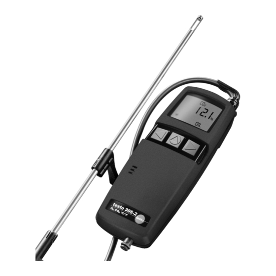
- Seite 1 305-1 testo 305-2 Abgasmessgerät Flue gas analyser Bedienungsanleitung Instruction manual...
-
Seite 2: Inhaltsverzeichnis
2.3 Messwerte und Gebietsversionen ........6 leisten, damit Ihnen lange Ausfallzeiten erspart bleiben. 3. Bedienung ............7 Wir hoffen, dass Sie an Ihrem neuen testo 305 lange Freude haben werden und es Sie bei Ihrer Arbeit hilfreich unterstützt. 3.1 Einstellen ..............7 3.2 Messen ................8 Allgemeine Hinweise 4. -
Seite 3: Grundlegende Sicherheitshinweise
Prüfen Sie vor jeder Messung das komplette Messsystem (Sonde, Kondensatfalle, Schläuche und - Das Gerät ist betriebsbereit. Anschlüsse) auf Dichtigkeit um Fehlmessungen durch Ziehen von Falschluft zu vermeiden. Sorgen Sie dafür, dass der Gasausgang am testo 305 stets frei ist. Nur so kann Messgas un- gehindert entweichen. 2.2 Anzeige- und Bedienelemente... -
Seite 4: Messwerte Und Gebietsversionen
S. 6) und bestätigen Sie Ihre Auswahl mit Abgasverlust bez. auf H 3 Wählen Sie mit die gewünschte Temperatureinheit (°C oder °F). Abgasverlust Nur bei testo 305-1: die gewünschte CO-Einheit (ppm oder mg/m Wählen Sie mit Abgasverlust bez. auf Umrechnungsformel: O -Bezug fest auf 3% eingestellt). -
Seite 5: Messen
3. Bedienung 3. Bedienung 3.2 Messen • Die Spitze des Thermoelements darf das Sondenrohr nicht Thermoelement Thermoelement berühren: Wenn nötig, biegen Sie die Spitze zurecht 1 Schalten Sie das Gerät ein, indem Sie den Ein-/Ausschalter an • An der Messsonde herunterlaufende Kondensattropfen kön- der linken Seite des Gerätes betätigen falsch! richtig! -
Seite 6: Wartung
4. Wartung 4. Wartung 4.1 Batterien/Akkus wechseln 4 Legen Sie einen neuen Filter ein und verschließen Sie das Filterfach mit dem Filterdeckel. Filterdeckel fest andrücken! Schalten Sie das Gerät vor dem Öffnen aus und leeren Sie 5 Verschließen Sie das Gerät mit dem Service-Deckel. die Kondensatfalle (siehe 4.2 Kondensatfalle leeren, S. -
Seite 7: Abgaspumpe Reinigen
4. Wartung 4. Wartung 12 Befestigen Sie mit einem Kreuz-Schraubendreher die Schrau- 5 Entnehmen Sie die Baugruppe aus dem Gehäuse-Oberteil. be am unteren Ende des Gerätes. 6 Lösen Sie die zweipolige Steckverbindung der Abgaspumpe 13 Legen Sie die Akkus/Batterien in das Batteriefach ein. Achten auf der Baugruppe Sie dabei auf die richtige Polung (siehe Kennzeichnung im 7 Ziehen Sie die Abgaspumpe... -
Seite 8: Fehlermeldungen
5. Fehlermeldungen 6. Technische Daten 6.1 Messbereiche und -genauigkeiten Sollten Störungen auftreten, die hier nicht beschrieben sind, wenden Sie sich bitte an den Testo- Kundenservice (siehe 9. Kundenservice, S. 18) oder Ihren Händler. Messart Messbereich Messwertgenauigkeit Anzeigeauflösung Störungen während der Nullung des Gerätes: Fehlermeldung Mögliche Ursachen... -
Seite 9: Berechnungsgrundlagen
21% - O Verbrennungstemperatur A2 / B: brennstoffspezifische Faktoren Testo gewährt auf dieses Produkt 24 Monate Garantie ab dem Zeitpunkt des Ersterwerbs. Für CO-Messzellen gilt 21%: Sauerstoffgehalt der Luft eine Garantie von 6 Monaten, für O -Messzellen von 12 Monaten. Von der Garantie abgedeckt sind alle Material- gemessener Sauerstoffgehalt in % und Fabrikationsfehler. -
Seite 10: Kundenservice
9. Kundenservice testo 305-1 testo 305-2 Abgasmessgerät Flue gas analyser Bedienungsanleitung Instruction manual... - Seite 21 Testo AG Postfach 11 40, D-79849 Lenzkirch Testo-Straße 1, D-79853 Lenzkirch Tel. (0 76 53) 6 81 - 0 (0 76 53) 6 81 - 1 00 E-Mail: info@testo.de http://www.testo.de 0973.3050/T/dr/PC_qxd/01.03...