Inhaltsverzeichnis
Werbung
Verfügbare Sprachen
Verfügbare Sprachen
Quicklinks
Werbung
Kapitel
Inhaltsverzeichnis
Fehlerbehebung

Verwandte Anleitungen für ECOLAB Elados EMP IV E00


Inhaltszusammenfassung für ECOLAB Elados EMP IV E00
- Seite 1 All manuals and user guides at all-guides.com Betriebsanleitung Operating Instruction Notice Technique Membrandosierpumpe Diaphragm Metering Pump Pompe doseuse à membrane Elados EMP IV E00 / E10 Deutsch English Francaise 417101090_EMP_IV_E00_E10 Rev. 8-06.13...
-
Seite 2: Inhaltsverzeichnis
All manuals and user guides at all-guides.com Inhaltsverzeichnis Allgemeines .......................... 3 Hervorhebungen / Aufzählungen ........................3 Allgemeines zu dieser Betriebsanleitung ......................3 EBS-Nummernreihe ............................3 Transportschäden ............................3 Gewährleistungsumfang ..........................4 Gerätekennzeichnung ............................4 Kontaktadresse / Hersteller ..........................4 Sicherheit ..........................5 Bestimmungsgemäße Verwendung ......................... -
Seite 3: Allgemeines
Wartungspersonal jederzeit zur Verfügung stehen. Bei einem Weiterverkauf ist die Betriebsanleitung immer mitzuliefern. EBS-Nummernreihe Innerhalb dieser Betriebsanleitung werden sowohl Artikelnummern, als auch EBS-Nummern dargestellt. EBS-Nummern sind Ecolab-interne Artikelnummern und werden „konzernintern“ verwendet. Transportschäden Wird beim Auspacken ein Transportschaden festgestellt, darf die... -
Seite 4: Gewährleistungsumfang
HINWEIS • der Benennung • des Types Nur so ist eine einwandfreie und schnelle Bearbeitung möglich. Kontaktadresse / Hersteller Ecolab Engineering GmbH Raiffeisenstraße 7 D-83313 Siegsdorf Telefon (+49) 86 62 / 61 0 Telefax (+49) 86 62 / 61 235 eMail: engineering-mailbox@ecolab.com... -
Seite 5: Sicherheit
Die Sicherheitshinweise und Hervorhebungen sind in jedem Fall zu beachten! ACHTUNG Bestimmungsgemäße Verwendung EMP-IV darf nur mit von Ecolab validierten Produkten verwendet werden. Bei ACHTUNG Verwendung unvalidierter Produkte kann keine Gewährleistung übernommen werden! Die Dosierpumpe ist für saubere, nicht abrasive Dosiermedien bis zu einer Viskosität von 100 mPas (Messmethode: Brookfield) geeignet. -
Seite 6: Fachkraft
All manuals and user guides at all-guides.com 2.3.2 Fachkraft Eine Person mit geeignetem Training, geeigneter Ausbildung und Erfahrungen die sie in die Lage versetzt Risiken zu erkennen und Gefährdungen zu vermeiden. In der Definition angelehnt an die EN 60204-1:2006. Pflichten des Betreibers In dem EWR (Europäischen Wirtschaftsraum) ist die nationale Umsetzung der Rahmenrichtlinie (89/391/EWG) sowie die dazugehörigen Einzelrichtlinien und davon HINWEIS... -
Seite 7: Lieferumfang
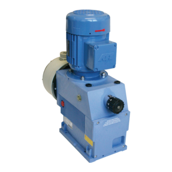
All manuals and user guides at all-guides.com Lieferumfang Der Lieferumfang besteht aus: Abb. 3.1 • Dosierpumpe ELADOS EMP IV E00 & E10 Abb. 3.2 • Betriebsanleitung Artikel Nr. 417101090 EBS Nr. auf Anfrage 417101090_EMP_IV_E00_E10 - 7 - Rev. 8-06.13... -
Seite 8: Funktionsbeschreibung
All manuals and user guides at all-guides.com Funktionsbeschreibung Mechanische Funktionen Die Dosierpumpe ELADOS EMP IV ist eine elektromotorisch betriebene Membran- Verdränger-Pumpe für den Einsatz im gewerblichen Bereich. Die Dosierpumpe ist für saubere, nicht abrasive Dosiermedien bis zu einer Viskosität von 100 mPas (Messmethode: Brookfield) geeignet. -
Seite 9: Aufbau
All manuals and user guides at all-guides.com Aufbau Abb. 5.1 Pos. Bezeichnung Elektrischer Motoranschluss Motor Öl-Einfüllöffnung mit Überdruckkappe Drehknopf für Hublängeneinstellung Ölstandsschauglas Pumpenkopf Druckventil Saugventil Ölablassschraube Anschluss Membranbruchsensor / Membranbruchablauf Fließrichtung des Dosiermediums Ausführung E00 / E10 Pos. Bezeichnung Klemmkasten Mechanische Hubverstellung EIN -/ AUS- Schalter (nur E10) Kontrolllampe (Anzeige „betriebsbereit“, nur E10) -
Seite 10: Geräteinstallation
All manuals and user guides at all-guides.com Geräteinstallation Hydraulische Installation 6.1.1 Installationsbeispiele Die Installation darf nur durch zugelassene Fachkräfte durchgeführt werden. Allgemeine Richtlinien und örtliche Installationsvorschriften sind hierbei zu beachten! Besondere Maßnahmen und Schutzeinrichtungen für die Dosierung gefährlicher bzw. ACHTUNG aggressiver Chemikalien sind hier nicht aufgeführt. - Seite 11 All manuals and user guides at all-guides.com Bei Dosierung in Rohrleitungen mit Unterdruck ist ein Druckhalteventil Abb. 6.3 in die Dosierleitung einzubauen. Ein Druckhalteventil oder ein Dosierventil ist kein HINWEIS absolut dicht schließendes Absperrorgan. Um ein Auslaufen des Dosiermediums bei Pumpen-Stillstand zu verhindern, empfehlen wir zusätzlich den Einbau eines Magnetventils, das mit der Pumpe freigegeben wird.
-
Seite 12: Anschluss Der Saug- Und Dosierleitungen
All manuals and user guides at all-guides.com Anschluss der Saug- und Dosierleitungen Achten Sie darauf, dass beim Anschluss der Saug- und Druckleitung die O-Ringe auf den VORSICHT Anschlüssen montiert sind, um die notwendige Abdichtung zu erreichen. HINWEIS Wir empfehlen die Verwendung einer passenden Sauglanze aus unserem Lieferprogramm. 6.2.1 Anschluss der Saug- und Dosierleitung mit Schlauchtülle Pos. -
Seite 13: Elektrische Installation / Netzanschluss
All manuals and user guides at all-guides.com Elektrische Installation / Netzanschluss ( Klemmkasten Innenansicht Version E00, 1-Phasen-Motor Pos. Bezeichnung Netzleitung Anschluss Anlaufelektronik* (im Klemmenkastendeckel) Der elektrische Anschluss ist nach den geltenden CE-Richtlinien herzustellen. Außerdem sind die jeweiligen Bestimmungen der Länder sowie örtliche EVU-Vorschriften zu beachten. -
Seite 14: Inbetriebnahme
All manuals and user guides at all-guides.com Inbetriebnahme Bei Inbetriebnahme das System wie in Kapitel „Entlüftung der Dosierpumpe“ beschrieben entlüften! HINWEIS Nach 24 Stunden Betrieb sind die Dosierkopfschrauben mit ca. 12 Nm diagonal nachzuziehen. Ist die Dosierleitung absperrbar, so sollte ein druckseitiges Überströmventil (Sicherheitsventil) zur Sicherung der Dosierleitung eingebaut werden, das beim max. -
Seite 15: Entlüftung Der Dosierpumpe
All manuals and user guides at all-guides.com Entlüftung der Dosierpumpe Bei einem anstehenden Dosiergegendruck von > 0,05 MPa (0,5 bar) empfehlen wir die Verwendung eines Mehrfunktionsventils aus unserem Zubehörprogramm. Ansonsten muss der montierte Kugelhahn (siehe Kapitel 6.1.1, „Installationsbeispiele“, Abb. 6.1) geöffnet oder die Dosierleitung anderweitig entlastet werden. HINWEIS Um eine optimale Ansaugleistung zu gewährleisten, sollte die Hublängeneinstellung auf 100% eingestellt sein. -
Seite 16: Wartung
All manuals and user guides at all-guides.com Wartung Vor Reparatur- und Wartungsarbeiten und Dosierung von gefährlichen Medien immer den Dosierkopf spülen, die Druckleitung entlasten und Schutzkleidung (Schutzbrille, Schutzhandschuhe und Schürze) tragen. Elektroreparaturen dürfen nur durch Elektrofachkräfte ausgeführt werden! Beim Öffnen von Abdeckungen oder Entfernen von Teilen, außer wenn dies ohne VORSICHT Werkzeug möglich ist, können spannungsführende Teile freigelegt werden. -
Seite 17: Austausch Des Pumpenkopfes Und Der Membrane
All manuals and user guides at all-guides.com Austausch des Pumpenkopfes und der Membrane Abb. 8.3 Pos. Bezeichnung Dosierkopfschraube Andrückplatte Dosierkopf Fördermembrane Zwischenring Schutzmembrane HINWEIS Bei geplanter Wiederverwendung der Ventile zunächst Ventile ausbauen wie unter Kapitel „Austausch von Saug- / Druckventil“ beschrieben. Vor dem Austausch der Membrane die Hublängeneinstellung auf unter 50 % einstellen! -
Seite 18: Getriebeöl Ablassen
All manuals and user guides at all-guides.com 8.3.1 Getriebeöl ablassen Getriebeentlüftungsschraube (Pos. 1) von Hand herausschrauben. Geeigneten Auffangbehälter (min. 0,9 l) unter Verschlussschraube (Pos. 3) halten. Verschlussschraube mit Steckschlüsseleinsatz (SW19) lösen und vorsichtig herausschrauben. Auslaufendes Öl in Auffangbehälter fließen lassen. ... -
Seite 19: Betriebsstörungen - Störungssuche
All manuals and user guides at all-guides.com Betriebsstörungen – Störungssuche Störung mögliche Ursache Behebung Netzkabel beschädigt Netzkabel wechseln Dosierpumpe arbeitet Falsche Spannung Netzspannung überprüfen nicht, keine Anzeige der Anschluss nach Klemmenplan LED grün (nur E10) Falsch angeschlossen überprüfen Pumpe saugt trotz Über Saugleitung den Dosierkopf Ablagerungen, Verkleben, Entlüftung und max. -
Seite 20: Verschleiß- Und Ersatzteile
All manuals and user guides at all-guides.com Verschleiß- und Ersatzteile 10.1 Ersatzteile Abb. 10.1 01400 02100 04500 06300 07500 Pos Beschreibung Artikelnummer (EBS-Nummer) SDV PPFPKE000 G1¼ - G1¼ -99 249075 (10001904) Saug- Druckventil PP/FPM (Viton B) G1¼“ SDV PPFPKE000 G2 – G2 -99 249503 (10079760) Saug- Druckventil PP/FPM (Viton B) G2“... -
Seite 21: Verschleißteilset
All manuals and user guides at all-guides.com 10.2 Verschleißteilset bestehend aus je 1 Stück: Saugventil • Druckventil • Membrane • Schutzmembrane • Beschreibung - Verschleißteilset EMP IV Material-Nr. (EBS-Nummer) 01400/02100 PPFPKE 250160 (10200645) 01400/02100 PPEPKE 250161 (10200648) 01400/02100 PVFPKE 250162 (10122651) 01400/02100 PVEPKE 250163 (auf Anfrage) 04500 PPFPKE... -
Seite 22: Technische Daten
All manuals and user guides at all-guides.com Technische Daten 11.1 Pumpenschlüssel 1. Elektrische Version E 00 Klemmkasten am Motor, mechanische Hubverstellung Klemmkasten am Motor, Ein- /Aus- schalter, mechanische Hubverstellung 2. Pumpenleistung 50 Hz (60 Hz) 01400 = 140 l/h (168 l/h) 02100 = 210 l/h (252 l/h) -
Seite 23: Beispiel Für Den Kompletten Pumpenschlüssel Einer Standardpumpe
All manuals and user guides at all-guides.com Pumpenschlüssel 2 11. Anschluss Saugseite = Schlauchtülle ID20 bis ID22 = Schlauchtülle ID25 bis ID27 = Schlauchtülle ID30 bis ID32 = Einlegeteil für Rohr AD 20 = Einlegeteil für Rohr AD 25 = Einlegeteil für Rohr AD 32 = ohne Anschluss 12.Anschluss Druckseite = Schlauchtülle ID20 bis ID22... -
Seite 24: Abmessungen
All manuals and user guides at all-guides.com 11.2 Abmessungen Abb. 11.1 Leistung Maße [mm] 00140 133,5 1¼" 00210 133,5 1¼" 00450 142,5 303,5 2" 00630 142,5 318,5 2" 00750 142,5 318,5 2" 11.3 Technische Daten „Übersichtslisten“ 11.3.1 Elektrische Daten Pumpentyp Bezeichnung 01400 02100... -
Seite 25: Allgemeine Daten - Standardpumpen
All manuals and user guides at all-guides.com 11.3.2 Allgemeine Daten – Standardpumpen Pumpentyp Bezeichnung 01400 02100 04500 06300 07500 Pumpenleistung [l/h]* / *** max. Dosiergegendruck [MPa (bar)] 0,1 (10) 0,8 (8) 0,6 (6) 0,4 (4) 0,3 (3) Hubmenge [1/min] Dosiermenge/Hub [ml] 50 Hz/60 Hz 19,4 29,2 62,5... -
Seite 26: Förderleistungen In Abhängigkeit Von Gegendruck Und Hubeinstellung
All manuals and user guides at all-guides.com 11.6 Förderleistungen in Abhängigkeit von Gegendruck und Hubeinstellung Einstellgenauigkeit + 15 %–5 % vom Nennwert, sämtliche Angaben bezogen auf Wasser bei 20 °C und gemäß der Hinweise in der Bedienungsanleitungen. 11.6.1 Förderleistung, Typ 01400 / 0,1 MPa (10 bar) Abb. -
Seite 27: Förderleistung, Typ 02100 / 0,8 Mpa (8 Bar)
All manuals and user guides at all-guides.com 11.6.3 Förderleistung, Typ 02100 / 0,8 MPa (8 bar) Abb. 11.4 Hublängeneinstellung (%) 11.6.4 Förderleistung, Typ 02100 / 1 MPa (10 bar) Abb. 11.5 Hublängeneinstellung (%) 417101090_EMP_IV_E00_E10 - 27 - Rev. 8-06.13... -
Seite 28: Förderleistung, Typ 04500 / 0,6 Mpa (6 Bar)
All manuals and user guides at all-guides.com 11.6.5 Förderleistung, Typ 04500 / 0,6 MPa (6 bar) Abb. 11.6 Hublängeneinstellung (%) 11.6.6 Förderleistung, Typ 06300 / 0,4 MPa (4 bar) Abb. 11.7 Hublängeneinstellung (%) 417101090_EMP_IV_E00_E10 - 28 - Rev. 8-06.13... -
Seite 29: Förderleistung, Typ 07500 / 0,3 Mpa (3 Bar)
All manuals and user guides at all-guides.com 11.6.7 Förderleistung, Typ 07500 / 0,3 MPa (3 bar) Abb. 11.8 Hublängeneinstellung (%) 417101090_EMP_IV_E00_E10 - 29 - Rev. 8-06.13... -
Seite 30: Demontage / Entsorgung
All manuals and user guides at all-guides.com Demontage / Entsorgung Demontage Die Demontage darf nur vom Fachpersonal durchgeführt werden. Achten Sie darauf, dass vor Beginn der Demontagearbeiten das Gerät komplett von der Stromversorgung getrennt wurde. Das Gerät muss sorgfältig durchgespült werden um Chemiereste zu beseitigen. Entsorgung Die Pumpe ist überwiegend aus Stahl (in bestimmtem Umfang auch aus Aluminium) hergestellt (außer der Elektroausrüstung) und ist entsprechend... -
Seite 31: Konformitätserklärung
All manuals and user guides at all-guides.com Konformitätserklärung 417101090_EMP_IV_E00_E10 - 31 - Rev. 8-06.13... - Seite 32 All manuals and user guides at all-guides.com Table of Contents General ..........................33 Highlighting / Lists ............................33 General information about these operating instructions ................. 33 EBS Article numbers ............................33 Transport damage ............................33 Warranty coverage ............................34 Unit marking ..............................34 Contact address / Manufacturer ........................
-
Seite 33: General
CAUTION unpacking! The carrier in question must be notified immediately, and a damage confirmation slip must be requested. A copy of the damage confirmation slip must be sent ATTENTION Ecolab Engineering GmbH immediately. 417101090_EMP_IV_E00_E10 - 33 - Rev. 8-06.13... -
Seite 34: Warranty Coverage
• The warranty claim is invalidated if the pump housing is opened. In addition, the general warranty and service conditions of the company Ecolab Engineering GmbH are applicable. Unit marking The information contained in these operating instructions only applies to the unit whose model no. -
Seite 35: Safety
ATTENTION Use as intended EMP IV may only be used in conjunction with products validated by Ecolab. Liability is ATTENTION not accepted if products are used which have not been validated! The metering pump is suitable for clean, non-abrasive metering media with a viscosity of up to 100 mPas (measuring method: Brookfield). -
Seite 36: Specialist
All manuals and user guides at all-guides.com 2.3.2 Specialist A person with appropriate training, schooling and experience enabling him or her to identify risks and avert danger. Definition based on EN 60204-1:2006. Duties of the owner Within the EEA (European Economic Area), national transposition of the framework directive (89/391/EEC) and corresponding individual directives, in particular the directive NOTE (89/655/EEC) concerning the minimum safety and health requirements for the use of... -
Seite 37: Delivery Scope
All manuals and user guides at all-guides.com Delivery scope The delivery scope consists of: Fig. 3.1 • Metering Pump ELADOS EMP IV E00 & E10 Fig. 3.2 • Operating Instructions (Art. No. 417101090) EBS No. on request 417101090_EMP_IV_E00_E10 - 37 - Rev. -
Seite 38: Functional Description
All manuals and user guides at all-guides.com Functional description Mechanical functions The metering pump ELADOS EMP IV is a diaphragm metering pump driven by an electrical motorfor industrial use. The metering pumps are suitable for use with clean, non-abrasive metering media with a viscosity of up to 100 mPas (measuring manner: Brookfield). -
Seite 39: Setup
All manuals and user guides at all-guides.com Setup Fig. 5.1 Pos. Description Electrical motor connection Motor Oil filler opening with overpressure cap Knob for setting the stroke length Oil-level gauge glass Pump head Pressure valve Suction valve Waste oil screw Connection for diaphragm sensor / diaphragm breakage drain Flow direction of the... -
Seite 40: Device Installation
All manuals and user guides at all-guides.com Device installation Hydraulic installation 6.1.1 Installation examples The installation must only be performed by authorized personnel and the general guidelines and local installation regulations must be observed! Specific measures and protection devices for the metering of dangerous or aggressive ATTENTION chemicals are not provided here. - Seite 41 All manuals and user guides at all-guides.com For metering in pipelines with underpressure, a pressure control valve Fig. 6.3 must be built into the metering pipe. A pressure control valve or a metering valve is not an NOTE absolutely hermetically sealing shutoff device. To prevent the running out of the metering medium when the pump is stopped, we also recommend the fitting of a solenoid valve which is approved for use with the pump.
-
Seite 42: Connecting The Suction Pipe And Pressure Pipe
All manuals and user guides at all-guides.com Connecting the suction pipe and pressure pipe When connecting the suction and pressure pipes, ensure that the O-rings are fixed to the CAUTION connectors so as to achieve the required seal. NOTE The use of an appropriate suction pipe from our product range is recommended. 6.2.1 Suction and metering line connection with hose nipple Fig. -
Seite 43: Electrical Connection / Power Suppy
All manuals and user guides at all-guides.com Electrical connection / Power suppy (Terminal box – internal view) Version E00, 1-phase motor Pos. Description Powerline Connection start-up electronics* (in terminal box cover) Power connection should be produced according to the current CE guidelines. Furthermore, the specific regulations, which were enforced in every single country, as well as all regulations established by local electric supply companies have to be observed. -
Seite 44: Startup
All manuals and user guides at all-guides.com Startup On start up, vent the system as described in chapter “venting the metering pump”! NOTE After 24 hours of operation, metering head screws should be diagonally tightened with approx. 12 Nm. If the metering line can be blocked off, an overflow valve (safety valve) which opens at the maximum allowed pressure should be installed on the pressure side for safeguarding the CAUTION metering line and pump. -
Seite 45: Venting The Metering Pump
All manuals and user guides at all-guides.com Venting the metering pump With an applied metering backpressure of > 0,05 MPa (0,5 bar), the use of a multifunction valve from our product range is recommended. Otherwise the fitted ball cock (see chapter 6.1.1 “Installation examples”, Fig. -
Seite 46: Maintenance
All manuals and user guides at all-guides.com Maintenance Prior to repair and maintenance work and metering of dangerous media, always rinse the metering head, relieve the pressure pipe and wear protective clothing (protective goggles, gloves and apron). Metering pumps must only be maintained by technically competent and authorized CAUTION persons. -
Seite 47: Metering Head And Diaphragm Replacement
All manuals and user guides at all-guides.com Metering head and diaphragm replacement Fig. 8.3 Pos. Description Metering head screws Pressing plate Metering head Delivery diaphragm Intermediate ring Protective diaphragm NOTE If you plan to reuse valves, they should be initially dismantled as described in chapter “Replacing the suction / pressure valve”. -
Seite 48: Gear Oil Draining
All manuals and user guides at all-guides.com 8.3.1 Gear oil draining Manually unscrew gear vent screw (pos. 1). Put a suitable collecting basin (min. volume 0.9 l) underneath the locking nut (pos. 3). Loosen locking nut with a socket for wrenches (SW 19) and unscrew it carefully. ... -
Seite 49: Operating Faults - Trouble Shooting
All manuals and user guides at all-guides.com Operating faults – Trouble shooting Fault Possible cause Rectification Metering pump does not Incorrect voltage Check power supply work, green LED not showing mains power cable damaged change mains power cable (only E10) wrong connection check connections acc. -
Seite 50: Wearing Parts And Spare Parts
All manuals and user guides at all-guides.com Wearing parts and spare parts 10.1 Spare parts Fig. 10.1 01400 02100 04500 06300 07500 Pos. Description Article no (EBS no.) SDV PPFPKE000 G1¼ - G1¼ -99 249075 (10001904) Suction- /Pressure valve PP/FPM (Viton B) G1¼“ SDV PPFPKE000 G2 –... -
Seite 51: Set Of Wearing Parts
All manuals and user guides at all-guides.com 10.2 Set of wearing parts Consisting of 1 piece each: • Suction valve • Pressure valve • Diaphragms • Protective diaphragm Description - Wearing part set EMP IV Article No. (EBS No.) 01400/02100 PPFPKE 250160 (10200645) 01400/02100 PPEPKE 250161 (10200648) -
Seite 52: Technical Specifications
All manuals and user guides at all-guides.com Technical Specifications 11.1 Pump key 1. Electrical Version E 00 Terminal box on motor, mechanical stroke adjustment Electrical motor connection, on/off switch mechanical stroke adjustment 2. Pump output 50 Hz (60 Hz) 01400 = 140 l/h (168 l/h) 02100 =... - Seite 53 All manuals and user guides at all-guides.com Pump key 2 11. Suction-side connection = hose nozzle ID20 to ID22 = hose nozzle ID25 to ID27 = hose nozzle ID30 to ID32 = insert for pipe AD 20 = insert for pipe AD 25 = insert for pipe AD 32 = without connection 12.
-
Seite 54: Dimensions
All manuals and user guides at all-guides.com 11.2 Dimensions Fig. 11.1 capacity measurement [mm] type 00140 133,5 1¼" 00210 133,5 1¼" 00450 142,5 303,5 2" 00630 142,5 318,5 2" 00750 142,5 318,5 2" 11.3 Technical specifications “Overview” 11.3.1 Electrical Data Pump type Description 01400... -
Seite 55: General Datas - Standard Pumps
All manuals and user guides at all-guides.com 11.3.2 General datas – Standard pumps Pump type Description 01400 02100 04500 06300 07500 Pump output [l/h]* / *** Max. metering backpressure [MPa (bar)] ***] 0.1 (10) 0.8 (8) 0.6 (6) 0.4 (4) 0.3 (3) Number of strokes [1/min] Metering quantity/stroke [ml] 50 Hz/60 Hz... -
Seite 56: Delivery Capacity Depending On The Backpressure And Stroke Setting
All manuals and user guides at all-guides.com 11.6 Delivery capacity depending on the backpressure and stroke setting Setting accuracy + 15 % - 5 % of the nominal value; all data relate to water at 20°C and comply with the notes in the operating instructions. 11.6.1 Delivery capacity, type 01400 / 0.1 MPa (10 bar) Fig. -
Seite 57: Delivery Capacity, Type 02100 / 0.8 Mpa (8 Bar)
All manuals and user guides at all-guides.com 11.6.3 Delivery capacity, type 02100 / 0.8 MPa (8 bar) Fig. 11.4 Stroke length setting (%) 11.6.4 Delivery capacity, type 02100 / 1 MPa (10 bar) Fig. 11.5 Stroke length setting (%) 417101090_EMP_IV_E00_E10 - 57 - Rev. -
Seite 58: Delivery Capacity, Type 04500 / 0.6 Mpa (6 Bar)
All manuals and user guides at all-guides.com 11.6.5 Delivery capacity, type 04500 / 0.6 MPa (6 bar) Fig. 11.6 Stroke length setting (%) 11.6.6 Delivery capacity, type 06300 / 0.4 MPa (4 bar) Fig. 11.7 Stroke length setting (%) 417101090_EMP_IV_E00_E10 - 58 - Rev. -
Seite 59: Delivery Capacity, Type 07500 / 0.3 Mpa (3 Bar)
All manuals and user guides at all-guides.com 11.6.7 Delivery capacity, type 07500 / 0.3 MPa (3 bar) Fig. 11.8 Stroke length setting (%) 417101090_EMP_IV_E00_E10 - 59 - Rev. 8-06.13... -
Seite 60: Dismantling / Disposal
All manuals and user guides at all-guides.com Dismantling / Disposal Dismantling The system may only be dismantled by specialist personnel. Before commencing dismantling, ensure that the unit has been fully isolated from the power supply. The device must be flushed through with care in order to get rid of any residual chemicals. Disposal The pump is predominantly made of steel (and also of aluminium to a certain extent) (apart from the electrical equipment) and is to be disposed of in... -
Seite 61: Declaration Of Conformity
All manuals and user guides at all-guides.com Declaration of Conformity 417101090_EMP_IV_E00_E10 - 61 - Rev. 8-06.13... - Seite 62 All manuals and user guides at all-guides.com Tables des martieres Généralités..........................63 Mises en garde / énumérations ........................... 63 Généralités concernant la présente notice d'utilisation ..................63 Numéros EBS ..............................63 Dégâts causés pendant le transport ........................63 Etendue de la garantie............................64 Identification de l'appareil ............................
-
Seite 63: Généralités
EMP-IV. La société de transport doit être immédiatement informée et doit fournir une déclaration de dommages. Une copie de la déclaration de dommages doit être ATTENTION immédiatement envoyée à la société Ecolab Engineering GmbH. 417101090_EMP_IV_E00_E10 - 63 - Rev. 8-06.13... -
Seite 64: Etendue De La Garantie
• la désignation • le type C'est la condition sine qua non pour un traitement rapide et efficace des demandes. Adresse de contact / Fabricant Ecolab Engineering GmbH Raiffeisenstraße 7 D-83313 Siegsdorf Téléphone (+49) 86 62 / 61 0 Télécopie (+49) 86 62 / 61 235 eMail: engineering-mailbox@ecolab.com... -
Seite 65: Sécurité
Utilisation conforme La pompe EMP-IV ne doit être utilisée qu'avec des produits validés par Ecolab. Aucune ATTENTION garantie ne saurait être honorée en cas d'utilisation de produits non validés ! La pompe doseuse est conçue pour des fluides de dosage propres non abrasifs jusqu'à une viscosité... -
Seite 66: Personne Qualifiée
All manuals and user guides at all-guides.com 2.3.2 Personne qualifiée Une personne possédant la formation, l'entraînement et l'expérience appropriés lui permettant de reconnaître les risques et d'éviter les dangers. Définition tirée de la norme EN 60204-1:2006. Obligations de l'exploitant Dans l'EEE (Espace économique européen), la transposition en droit national de la directive cadre (89/391/CEE) ainsi que les directives individuelles connexes, dont en AVIS particulier la directive (2009/104/CE) concernant les prescriptions minimales de sécurité... -
Seite 67: Contenu De La Livraison
All manuals and user guides at all-guides.com Contenu de la livraison La livraison comprend les éléments suivants : Fig. 3.1 • Pompe doseuse ELADOS EMP IV E00 & E10 Fig. 3.2 • Notice technique (art. n° 417101090) EBS n° sur demande 417101090_EMP_IV_E00_E10 - 67 - Rev. -
Seite 68: Description Du Fonctionnement
All manuals and user guides at all-guides.com Description du fonctionnement Fonctions mécaniques La pompe doseuse ELADOS EMP IV est une pompe volumétrique électromécanique à membrane destinée à une utilisation dans le domaine commercial. Lapompe doseuse convient à l’utilisation de substances dosées propres et non abrasives dont la viscosité... -
Seite 69: Structure
All manuals and user guides at all-guides.com Structure Fig. 5.1 Pos. Désignation Raccord du moteur électrique Moteur Ouverture de remplissage d’huile avec clapet de surpression Bouton tournant pour le réglage de la longueur de course Verre indicateur de niveau d’huile de niveau d’huile Tête de pompe Soupape de pression... -
Seite 70: Installation De L'appareil
All manuals and user guides at all-guides.com Installation de l’appareil Installation hydraulique 6.1.1 Exemples d’installation L’installation doit être exécutée uniquement par des ouvriers spécialisés et agréés ; de plus, il est impératif d’observer les directives générales et les prescriptions d’installation locales ! ATTENTION Des mesures spéciales et des dispositifs de protection particuliers pour le dosage de... - Seite 71 All manuals and user guides at all-guides.com Il faut installer une soupape de maintien de la pression dans la conduite Fig. 6.3 de dosage lors du dosage dans des tuyauteries où règne une dépression. Une soupape de maintien de la pression ou une REMARQUE soupape de dosage n’est pas un organe d’arrêt qui se ferme avec une étanchéité...
-
Seite 72: Raccordement De La Conduite D'aspiration Et De La Conduite De Dosage Avec Une Pièce Conique
All manuals and user guides at all-guides.com Raccordement de la conduite d’aspiration et de la conduite de dosage avec une pièce conique Pour le raccordement de la conduite d’aspiration et de la conduite de pression, veiller à PRECAUTION ce que les joints toriques soient montés sur les raccords pour obtenir l’étanchéité nécessaire. -
Seite 73: Connexions Électriques / Connexion Au Réseau
All manuals and user guides at all-guides.com Connexions électriques / Connexion au réseau (Boîte de connexions, vue intérieure) Version E00, moteur à 1 phase Pos. Désignation Conducteur de réseau Connexion de l’unité électronique de démarrage* (dans le couvercle du coffret des bornes) La connexion électrique doit être effectuée selon les directives CE en vigueur ainsi que selon les dispositions du pays respectif et les règlements locaux des entreprises... -
Seite 74: Mise En Service
All manuals and user guides at all-guides.com Mise en service Lors de la mise en service, il convient de purger le système comme décrit au chapitre 7.5« Purge de la pompe deseuse »! REMARQUE Après 24 heures de fonctionnement, les vis de la tête de dosage doivent être resserrées diagonalement à... -
Seite 75: Purge De La Pompe Doseuse
All manuals and user guides at all-guides.com Purge de la pompe doseuse Lors d’une contre-pression de dosage existante supérieure à 0,05 MPa (0,5 bar), nous recommandons d’utiliser une soupape multifonctions appartenant à notre programme d’accessoires. Sinon, le robinet à boisseau sphérique monté (recommandation voir au chapitre 6.1.1 «... -
Seite 76: Maintenance
All manuals and user guides at all-guides.com Maintenance Avant de procéder aux travaux de maintenance et de réparation, ainsi qu’au dosage de matières dangereuses, il faut toujours rincer la tête de dosage, décharger la conduite de pression et porter des vêtements de protection (lunettes de protection, gants de protection et tablier). -
Seite 77: Remplacement De La Tête De Pompe Et De La Membrane
All manuals and user guides at all-guides.com Remplacement de la tête de pompe et de la membrane Fig. 8.3 Pos. Désignation Vis de la tête de dosage Plaque de pression Tête de pompe Membrane de convoyage Rondelle intermédiaire Membrane de protection REMARQUE S’il est prévu de réutiliser les soupapes, ces dernières doivent être tout d’abord... -
Seite 78: Ecoulement De L'huile D'engrenage
All manuals and user guides at all-guides.com 8.3.1 Ecoulement de l’huile d’engrenage Dévisser la vis de purge de la transmission (pos. 1) à la main. Placer un récipient de recueil approprié (d’un volume d’au moins 0.9 l) sous la vis de fermeture (pos. -
Seite 79: Défauts De Service - Tableau D'erreurs
All manuals and user guides at all-guides.com Défauts de service – Tableau d’erreurs Défaut Origine possible Elimination Pompe doseuse ne marche Tension incorrecte / pas, voyant lumineux vert Vérifier la tension d'alimentation pas de tension pas allumé ou pas d’indication sur affichage Contrôler le branchement (plan de Pompe mal branchée (E10) -
Seite 80: Pièces D'usure Et Pièces Détachées
All manuals and user guides at all-guides.com Pièces d’usure et pièces détachées 10.1 Pièces détachées Fig. 10.1 01400 02100 04500 06300 07500 Pos Désignation Article n° (EBS n°) SDV PPFPKE000 G1¼ - G1¼ -99, Soupape 249075 (10001904) d’aspiration et de pression PP/FPM (Viton B) G1¼“ SDV PPFPKE000 G2 –... -
Seite 81: Kit De Pièces D'usure Complet
All manuals and user guides at all-guides.com 10.2 Kit de pièces d'usure complet Comportant à chaque fois 1 pièce des composants suivants : Soupape d'aspiration • Soupape de refoulement • Membrane • Membrane de protection • Désignation - Kit de pièces d'usure EMP IV Article n°... -
Seite 82: Données Techniques
All manuals and user guides at all-guides.com Données techniques 11.1 Codes de pompe 1. Version électrique E 00 = boîte terminal sur le moteur, réglage mécanique de la course Boîte terminal sur le moteur, interrupteur marche/arrêt, réglage mécanique de la course 2. - Seite 83 All manuals and user guides at all-guides.com Codes de pompe 2 11. Raccord du côté aspiration = embout à olive ID20 jusqu’à ID22 = embout à olive ID25 jusqu’à ID27 = embout à olive ID30 jusqu’à ID32 = pièce d’insertion pour tuyauterie AD 20 = pièce d’insertion pour tuyauterie AD 25 = pièce d’insertion pour tuyauterie AD 32 = sans raccord...
-
Seite 84: Dimensions
All manuals and user guides at all-guides.com 11.2 Dimensions Fig. 11.1 Débit Dimensions [mm] Type 00140 133,5 1¼" 00210 133,5 1¼" 00450 142,5 303,5 2" 00630 142,5 318,5 2" 00750 142,5 318,5 2" 11.3 Données techniques 11.3.1 Donées électrique Type de pompe Désignation 01400 02100 04500 06300 07500 Tension d’alimentation... -
Seite 85: Donées Géneralés - Standard Pompe
All manuals and user guides at all-guides.com 11.3.2 Donées géneralés – standard pompe Type de pompe Désignation 01400 02100 04500 06300 07500 Débit de la pompe [l/h]* / *** Contre-pression maximale de dosage [MPa (bar)] 0,1 (10) 0,8 (8) 0,6 (6) 0,4 (4) 0,3 (3) Nombre de courses [1/min] pour 50 Hz Quantité... -
Seite 86: Performances De Débit En Fonction De La Contre-Pression Et Du Réglage De Course
All manuals and user guides at all-guides.com 11.6 Performances de débit en fonction de la contre-pression et du réglage de course Exactitude de réglage : + 15 % - 5 % dela valeur nominale ; toutes les indications se réfèrent à de l’eau sous une température de 20 °C et conformément aux remarques figurant dans les modes d’emploi. -
Seite 87: Performance De Debit, Type 02100 / 0,8 Mpa (8 Bar)
All manuals and user guides at all-guides.com 11.6.3 Performance de debit, type 02100 / 0,8 MPa (8 bar) Fig. 11.4 Réglage de la longueur de course (%) 11.6.4 Performance de debit, type 02100 / 1 MPa (10 bar) Fig. 11.5 Réglage de la longueur de course (%) 417101090_EMP_IV_E00_E10 - 87 -... -
Seite 88: Performance De Debit, Type 04500 / 0,6 Mpa (6 Bar)
All manuals and user guides at all-guides.com 11.6.5 Performance de debit, type 04500 / 0,6 MPa (6 bar) Fig. 11.6 Réglage de la longueur de course (%) 11.6.6 Performance de debit, type 06300 / 0,4 MPa (4 bar) Fig. 11.7 Réglage de la longueur de course (%) 417101090_EMP_IV_E00_E10 - 88 -... -
Seite 89: Performance De Debit, Type 07500 / 0,3 Mpa (3 Bar)
All manuals and user guides at all-guides.com 11.6.7 Performance de debit, type 07500 / 0,3 MPa (3 bar) Fig. 11.8 Réglage de la longueur de course (%) 417101090_EMP_IV_E00_E10 - 89 - Rev. 8-06.13... -
Seite 90: Démontage / Mise Au Rebut
All manuals and user guides at all-guides.com Démontage / mise au rebut Démontage Le démontage ne peut être effectué que par un personnel qualifié. S'assurer avant le début des travaux de démontage que l'appareil a été entièrement débranché de l'alimentation électrique. -
Seite 91: Déclaration De Conformité
All manuals and user guides at all-guides.com Déclaration de conformité 417101090_EMP_IV_E00_E10 - 91 - Rev. 8-06.13... - Seite 92 Letzte Änderung: 28.06.2013 last changing: © Copyright Ecolab Engineering GmbH, 2013 All rights reserved Alle Rechte vorbehalten. Nachdruck, auch auszugsweise, nur mit Genehmigung der Firma Ecolab Engineering GmbH gestattet. Reproduction, also in part, only with permission of Ecolab Engineering GmbH.