PeakTech 2725 Bedienungsanleitung

Verwandte Anleitungen für PeakTech 2725


Inhaltszusammenfassung für PeakTech 2725
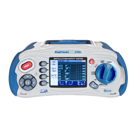
- Seite 1 All manuals and user guides at all-guides.com 2755 Bedienungsanleitung / Operation Manual Installationstester Installation Safety Tester...
-
Seite 2: Inhaltsverzeichnis
All manuals and user guides at all-guides.com Thema Seite 1. Einleitung 2. Sicherheitshinweise 2.1. Sicherheitssysmbole am Gerät 2.2. Erfüllte Normen 3. Technische Merkmale 3.1. Gerätespezifikationen 3.2. Begriffserklärung 4. Vorbereitung 4.1. Funktionstasten 4.2. Anschlüsse 4.3. Akku/Batterien und Sicherungen 4.4. Anzeige / Symbole 5. - Seite 3 All manuals and user guides at all-guides.com Issue Page 1. Introduction 2. Safety Precautions 2.1. Safety Symbols 2.2. Used standards 3. Specifications 3.1 General Specifications 3.2. Explanation of therms 4. Control 4.1. Function keys 4.2. Connections 4.3. Batteries and Fuses 4.4.
-
Seite 4: Einleitung
All manuals and user guides at all-guides.com 1. Einleitung Dieses Gerät erfüllt die EU-Bestimmungen 2004/108/EG (elektromagnetische Kompatibilität) und 2006/95/EG (Niederspannung) entsprechend der Festlegung im Nachtrag 2004/22/EG (CE- Zeichen). Überspannungskategorie CAT III 600V Verschmutzungsgrad 2. 2. Sicherheitshinweise Zur Betriebssicherheit des Gerätes und zur Vermeidung von schweren Verletzungen durch Strom- oder Spannungsüberschläge bzw. -
Seite 5: Sicherheitssysmbole Am Gerät
All manuals and user guides at all-guides.com 2.1. Sicherheitssysmbole am Gerät Achtung! Stromschlaggefahr! Öffnen Sie nicht das Gehäuse während eines Messvorganges! Achtung! Keine Überspannung an die Eingangsbuchsen anlegen! Entfernen Sie die Prüfleitungen vor dem Öffnen des Batteriefachs! Reinigung – Benutzen Sie nur trockene Tücher zum Reinigen des Gehäuses! Beachten Sie alle Sicherheitshinweise aus der Bedienungsanleitung! Erdung... -
Seite 6: Technische Merkmale
All manuals and user guides at all-guides.com 3. Technische Merkmale Schleifenwiderstand L-PE (Hi-Amp) Bereich (Ω) Auflösung (Ω) Genauigkeit 0.23 – 9.99 0.01 10.0 – 99.9 ±(4% v.M.+ 6 Stellen) 100 – 999 ………..…………….………………………………………………… 8.0 A ~ 25.0 A Prüfstrom Spannungsbereich ……………………………………………195 V AC. – 260 V AC (50,60Hz) L- PE (Kein Auslösen des FI) Bereich (Ω) Auflösung (Ω) - Seite 7 All manuals and user guides at all-guides.com Genauigkeit beim angegebenen Prüfstrom Prüfstrom Genauigkeit der Auslösezeit x1/2 ±(1% + 1 ms) ±(1% + 1 ms) ±(1% + 1 ms) ±(1% + 1 ms) Sinuswellenform (AC) Form des Prüfstroms Pulswellenform (DC) General (G - nicht verzögert), FI Form Selektive (S - zeitverzögert) Anfängliche Polarität des Prüfstroms...
- Seite 8 All manuals and user guides at all-guides.com Isolationswiderstand (Isolation) Prüf- Messbereich Auflösung Genauigkeit Prüfstrom Kurzschlussstrom spannung 0.125~4.000 MΩ 0.001MΩ ±2% + 10St. 4.001~40.00 MΩ 0.01MΩ ±2% + 10St. 125V ≥ 1mA 125kΩ (0%~+10%) 40.01~400.0 MΩ 0.1MΩ ±4% + 5St. Last 400.1~1000 MΩ...
-
Seite 9: Gerätespezifikationen Stromversorgung
All manuals and user guides at all-guides.com 3.1. Gerätespezifikationen Stromversorgung 12 V DC 8x 1,2V Ni-Mh Akkus (2500mAh) oder äquivalent Batteriebetriebsdauer ca.15 Stunden (typisch) Überspannungskategorie CAT III 600 V Schutzklasse II (doppelt isoliert) Schutzart IP65 (staub & wasserdicht) LCD- Anzeige 320x240 Pixel Betriebstemperatur 0°C ~ 45 °C... - Seite 10 All manuals and user guides at all-guides.com Die Schleifenimpedanz gibt die Summe aller Widerstandskomponenten einer Stromschleife an, welche bei einem Fehler vom Fehlerstrom durchflossen wird. Dieser LOOP Widerstand muss möglichst gering sein bis die Schutzmaßnahmen ausgelöst haben und den Stromkreis unterbrechen, damit bei hohen Fehlerströmen keine Hitze in den Leitungen entsteht, wodurch ein Brand entstehen kann.
- Seite 11 All manuals and user guides at all-guides.com Eine Durchgangsprüfung dient zur Überprüfung von intakten Verbindungen in einem nicht aktiven Stromkreis. Sind alle Klemmen korrekt angeschlossen, sollte der Widerstand möglichst gering sein. Bei korrodierten, verschmorten oder Continuity schlecht verschraubten Verbindungen ist der Widerstand (Durchgang) höher (Übergangswiderstand), was zu einer Erhitzung der Klemmen- und schließlich zu einem Brand führen kann.
-
Seite 12: Vorbereitung
All manuals and user guides at all-guides.com 4. Vorbereitung 4.1. Funktionstasten Nummer Beschreibung Startet den ausgewählten Test. Die Test-Taste wird durch ein "Touch-Pad" umgeben. Das Touchpad erfasst das Potential zwischen dem Anwender und der PE-Klemme. Wenn Sie eine 100-V-Schwelle überschreiten, wird das Warnsymbol (2) am Touchpad beleuchtet. -
Seite 13: Anschlüsse
All manuals and user guides at all-guides.com 4.2. Anschlüsse Nummer Beschreibung Zusatzeingangsbuchsen für Hochspannungstastkopf L – Eingang Phase PE – Eingang Erdung N – Eingang Neutralleiter Zusatzeingangsbuchsen für Hochspannungstastkopf TV OUT -Buchse System Reset USB Anschluss SD-Kartenslot Audio Out Buchse Buchse zur Spannungsversorgung mit AC-Adapter / Akkuladung -10-... -
Seite 14: Akku/Batterien Und Sicherungen
All manuals and user guides at all-guides.com 4.3. Akku/Batterien und Sicherungen Nummer Beschreibung Sicherung 5A/600V; 6x32mm Sicherung 5A/600V; 6x32mm Sicherung 500mA/600V; 6x32mm 8 x 1,2V AA Ni-Mh Akku (2500mAh) oder äquivalente 1,5V AA Batterien -11-... -
Seite 15: Anzeige / Symbole
All manuals and user guides at all-guides.com zeige / Symbole 4.4. An Nummer Funktion / Symbol Wert / Bedeutung AUTO ½ (FI-Test) RAMP Loop/PFC L-PE (Schleifenimpedanz) V/Phase L-PE (Spannung / Phasendrehung) 0.5 1.0 2.0 Continuity 5.0 (Durchgangsprüfung) 10.0 20.0 50.0 125V Terminal Voltage 250V... - Seite 16 All manuals and user guides at all-guides.com Nummer Funktion / Symbol Wert / Bedeutung 30mA 100mA 300mA Trip Current 500mA (Auslösestrom) 650mA 1000mA 10mA Current NO Trip (Auslöseverhalten) Hi Amp Beeper (Summer) Normaler FI- sinusförmiger Prüfstrom Selektiver FI- sinusförmiger Prüfstrom Type of RCD (Art des FI) Normaler FI- Halbwelle-Prüfstrom...
- Seite 17 All manuals and user guides at all-guides.com Nummer Funktion / Symbol Wert / Bedeutung Summer Sperre für fortlaufende Prüfung aktiv Haltefunktion Datenlogger Bluetooth Verbindung aktiviert Wird bei Überhitzung angezeigt Anzeige bei zeitverzögerten FI‘s (30 Sekunden) Test wird aktuell ausgeführt Primäre Anzeige mit aktuellem Messwert Einheit des aktuellen Messwertes Sekundäre Anzeige mit aktuellem Messwert Einheit des aktuellen Messwertes...
-
Seite 18: Bedienung
All manuals and user guides at all-guides.com Nummer Funktion / Symbol Wert / Bedeutung N-PE N-PE Wert (Neutralleiter zu Erdung) L-N Wert (Phase zu Neutralleiter) L-PE L-PE Wert (Phase zu Erdung) Erdschlussstrom. Berechnet die Spannung und Schleifenimpedanz, die von Phase zu Schutzleiter gemessen wird. Voraussichtlicher Kurzschlussstrom, welcher fließen kann, wenn Phase gegen Phase oder Neutralleiter kurzgeschlossen wird. -
Seite 19: Symbole Und Meldungen In Der Spannungsfunktion
All manuals and user guides at all-guides.com 5.1.1 Symbole und Meldungen in der Spannungsfunktion Zeigt die richtigen Eingangsverbindungen an. Der Benutzer sollte die Messleitungen an die entsprechenden Klemmen anschließen. Zeigt an, dass keine Verbindung auf dem PE- Eingangsanschluss ist. Zeigt an, dass die L-Verbindung auf dem N- Eingangsanschluss liegt und umgekehrt (Verpolung) Wenn die Verdrahtungsbedingungen anders als üblich sind (also L, N und PE ohne korrekte... -
Seite 20: Symbole Und Meldungen In Der Fi (Rcd) Funktion
All manuals and user guides at all-guides.com Fehlermeldungen: Funktion in Betrieb – Messung wird durchgeführt Mess... : RCD Trip: Während der Messung wurde der RCD (FI-Schutzschalter) ausgelöst, daher wurde kein Testergebnis erhalten Erscheint während der „No Trip“-Schleifenmessung und deutet an, dass der Noise: angezeigte Wert wegen "Netzinterferenzen"... -
Seite 21: Symbole Und Meldungen In Der Low Ohm- Oder Durchgangsfunktion
All manuals and user guides at all-guides.com 5.1.4 Symbole und Meldungen in der LOW OHM- oder Durchgangsfunktion Zeigt die korrekten Eingangsverbindungen an: Der Nutzer sollte die Prüfleitungen nach der Farbkodierung richtig anschließen. Batteriespannung ist ungenügend. Das Symbol blinkt und ein Warngeräusch ertönt. Der Eigenwiderstand der Prüfleitungen ist Bestandteil der Messung. -
Seite 22: Anwendung Der Loop / Pfc-Funktion
All manuals and user guides at all-guides.com 5.2 Anwendung der LOOP / PFC-Funktion 1. Bevor Sie eine Schleifenimpedanz-Messung machen, verwenden Sie die „Zero“ Funktion, um die verwendeten Messleitungen oder das Netzkabel zu „nullen“. Zuvor müssen alle drei Messleitungsenden (zu Tester-Eingängen „L“, „N“, „PE“ führend) miteinander kurzgeschlossen werden. -
Seite 23: No Trip" Schleifenmessung (Loop Messung)
All manuals and user guides at all-guides.com 5.2.1 „No Trip“ Schleifenmessung (Loop Messung) Die „No Trip“ Schleifenmessung (LOOP Messung) sollte gewählt werden, wenn der zu messende Stromzweig durch einen FI-Schutzschalter (RCD) geschützt wird, dessen Auslösewert bei 30mA oder höher liegt. 1. -
Seite 24: Loop / Pfc Funktionsmenü
All manuals and user guides at all-guides.com 5.2.2 LOOP / PFC Funktionsmenü Hauptanzeige Menüanzeige F1 Taste Pop-Up Menü für Loop / PFC-Menü wird aktiviert. F2 Taste Pop-Up Menü für das Strommenü wird aktiviert. F3 Taste Keine Menüfunktion vorhanden F4 Taste Drücken Sie die Taste F4 für die Nullungsfunktion. -
Seite 25: Hi Amp Loop/Pfc Messung
All manuals and user guides at all-guides.com Drücken Sie die Test-Taste, wenn eine Wiederholung der Messung notwendig ist. Wenn eines der folgenden Symbole angezeigt wird, kann die Messung nicht durchgeführt werden: 5.2.3 Hi Amp LOOP/PFC Messung Es sollte die Hi Amp LOOP Messung ausgewählt werden, wenn der Stromkreis nicht durch Einbeziehung eines FI (RCD) geschützt wird. -
Seite 26: L-N Impedanz Messung
All manuals and user guides at all-guides.com Wenn eines der folgenden Symbole angezeigt wird, kann die Messung nicht durchgeführt werden: 5.2.4. L-N Impedanz Messung 1. Drehen Sie den Drehschalter in die LOOP/PSC - Position. 2. Drücken Sie die F1-Taste, um von L-PE auf L-N umzuschalten. 3. -
Seite 27: Fi (Rcd)-Test Funktion
All manuals and user guides at all-guides.com 5.2.5 FI (RCD)-Test Funktion Sie können durch Drücken und Halten der F3-Taste (länger als 2 Sekunden) die U -Spannung wählen (25 V oder 50 V). Der angezeigte U -Wert, ist die Berührungsspannung. Funktionstastenbeschreibung: Taste RCD t∆... -
Seite 28: Anwendung Der Fi-Messfunktionen Über Die F1-Taste
All manuals and user guides at all-guides.com 5.2.5.1 Anwendung der FI-Messfunktionen über die F1-Taste Anschluss bei der FI-Messung 5.2.5.2 Anwendung des AUTO Modus Anzeige des AUTO Modus Drehen Sie den Drehschalter in die Position RCD Der Einstiegsbildschirm ist das Setup des AUTO-Modus Mit der F2-und F3-Taste, wählen Sie die Bewertung und den Typ des FIs aus Messleitungen anschließen, wie in der Abbildung gezeigt. -
Seite 29: Anwendung Des X½, X1, X2 Und X5 Modus In Manueller Auswahl
All manuals and user guides at all-guides.com 5.2.5.3 Anwendung des x½, x1, x2 und x5 Modus in manueller Auswahl 1. Drehen Sie den Drehschalter in die Position RCD ½ 2. Drücken Sie F1-Taste, um aus dem AUTO x , x1, x2 und x5 Modus zu wählen 3. -
Seite 30: Anwendung Der „Ramp"-Funktion
All manuals and user guides at all-guides.com 5.2.5.4 Anwenden der „Ramp“-Funktion Bei unbekannter Auslösegröße des Fehlerstroms kann die Ramp-Funktion genutzt werden, um einen stetig steigenden Prüfstrom auszugeben. Wenn dieser den Auslösestrom des FI erreicht und damit ausgelöst hat, kann der Messwert als Bemessungsgrundlage für den FI verwendet werden. 1. -
Seite 31: Anwendung Der Spannungsfunktion
All manuals and user guides at all-guides.com Menüanzeige F1 Taste Pop-Up Menü für Messart (Auto, Time, Ramp) wird geöffnet. F2 Taste Pop-Up Menü für Nenn-Auslösestrom (10mA bis 650mA) wird geöffnet. F3 Taste Pop-Up Menü für FI-Art und Form des Prüfstroms (Allgemein, Selektiv / Sinus, Halbwelle) wird geöffnet. -
Seite 32: Anwendung Der Phasensequenzfunktion (Drehrichtungsanzeige)
All manuals and user guides at all-guides.com 5.2.8 Anwendung der Phasensequenzfunktion (Drehrichtungsanzeige) Startbild der Phasensequenzmessung Anschluss der Phasensequenzmessung 1. Drehen Sie den Drehschalter in die Position V 2. Drücken Sie F1, um auf Phasensequenz umzuschalten 3. Schließen Sie die Messleitungen an L1, L2, L3 an, wie im Bild dargestellt 4. -
Seite 33: Voltage/Phase Funktionsmenüs
All manuals and user guides at all-guides.com 5.2.9. Voltage/Phase Funktionsmenüs Hauptanzeige Menüanzeige F1 Taste Pop-up Menü für Spannungsmessung (L-PE, L-N, N-PE) oder Phasensequenz wird aktiviert F2 Taste Keine F3 Taste Keine F4 Taste Keine ▲ Taste Drücken um die aktuellen aktiven Optionen auszuwählen. ▼... -
Seite 34: Isolationswiderstandsmessung
All manuals and user guides at all-guides.com 5.3. Isolationswiderstandsmessung 5.3.1 Funktionsmenüs der Isoaltionsprüfung Hauptanzeige Menüanzeige F1 Taste Pop-Up Menü für die Prüfspannung wird aktiviert. F2 Taste Pop-Up Menü für den Warnsummer wird aktiviert. F3 Taste Pop-Up Menü für den Warnsummer wird aktiviert. F4 Taste Pop-Up Menü... -
Seite 35: Messung Des Isolationswiderstands
All manuals and user guides at all-guides.com 5.3.2 Messung des Isolationswiderstands Isolationswiderstand / Schalter und Anschlusseinstellungen Messungen dürfen nur an spannungsfreien Stromkreisen durchgeführt werden. 1. Schalten Sie den Drehschalter in die „INSULATION“-Position. 2. Verwenden Sie die Klemmen L und N (rot und schwarz) für diesen Test. 3. - Seite 36 All manuals and user guides at all-guides.com Die beste Genauigkeit wird erzielt, wenn der Abstand des mittleren Erdspießes ca. 62% der Strecke der Entfernung zum am weitesten entfernten Erdspieß erreicht, wie im folgenden Bild dargestellt: Die Erdspieße sollten hierbei in einer geraden Linie aufgestellt und die Leitungen getrennt werden, um eine gegenseitige Kopplung zu vermeiden.
-
Seite 37: Erdungswiderstand Funktionsmenü
All manuals and user guides at all-guides.com 5.4.1. Erdungswiderstand Funktionsmenü Hauptanzeige F1 Taste Keine F2 Taste Keine F3 Taste Keine F4 Taste Nullung der Prüfleitungen ▲ Taste Drücken um die aktuellen aktiven Optionen auszuwählen. ▼ Taste Drücken um die aktuellen aktiven Optionen auszuwählen. Enter Taste Bestätigen Sie die Benutzerauswahl. -
Seite 38: Optionen / Einstellungen
All manuals and user guides at all-guides.com Menüanzeige F1 Taste Pop-Up Menü zur Grenzwerteinstellung der Durchgangsprüfung F2 Taste Pop-Up zum Ein/Ausschalten des Summers F3 Taste Keine F4 Taste Nullung der Prüfleitungen ▲ Taste Drücken um die aktuellen aktiven Optionen auszuwählen. ▼... -
Seite 39: Systemeinstellungen
All manuals and user guides at all-guides.com 6.1. Systemeinstellungen Symbol Menu Languages - Spracheinstellungen Date/Time - Datum Zeit TV – TV Ausgang Memory - Datenspeicheroptionen Auto screen-off – Automatische Bildschirmabschaltung Auto power-off – Automatische Geräteabschaltung System default settings – Werkseinstellungen System upgrade –... -
Seite 40: Sprachauswahl
All manuals and user guides at all-guides.com 6.1.1. Sprachauswahl Drücken Sie die ▲oder ▼ Tasten, um durch das Sprachmenü (Language) zu navigieren und bestätigen Sie die Auswahl mit der □ –Taste (Enter). Hinweis: Die zur Auswahl stehenden Sprachen können sich mit neueren Firmware-Versionen ändern. -
Seite 41: Tv-Ausgabe
All manuals and user guides at all-guides.com 6.1.3. TV-Ausgabe Das Gerät verfügt über die Möglichkeit das Anzeigebild als TV-Out Signal an einen Fernseher weiterzuleiten. Drücken Sie die ▲oder ▼ Tasten, um durch das Menü zu navigieren und bestätigen Sie die Auswahl mit der □... -
Seite 42: Automatische Bildschirmabschaltung
All manuals and user guides at all-guides.com 6.1.5. Automatische Bildschirmabschaltung Um die Einsatzdauer der geladenen Akkus zu verlängern, sollte sich der Bildschirm nach einigen Minuten automatisch deaktivieren (Auto Screen Off), da die Hintergrundbeleuchtung der größte Einzelverbraucher im Gerät ist. Drücken Sie die ▲oder ▼ , um zwischen den verschiedenen Optionen umzuschalten, wobei 3 Minuten der Standard ist. -
Seite 43: Werkseinstellungen
All manuals and user guides at all-guides.com 6.1.7. Werkseinstellungen Sollte das Gerät Probleme bei der Anwendung zeigen oder versehentlich Einstellungen verändert worden sein, kann eine Rücksetzung auf Werkseinstellungen (System Default) helfen. Drücken Sie die ▲oder ▼ Tasten, um zwischen YES (JA) oder NO (NEIN) umzuschalten und bestätigen Sie die Auswahl mit der □... -
Seite 44: Datenspeicher, Schnittstellen Und Aufnahmefunktion
All manuals and user guides at all-guides.com 7. Datenspeicher, Schnittstellen und Aufnahmefunktion 7.1 Aufnahmefunktion (Run Settings) Symbole Menü Bluetooth Ein/Aus Datenaufzeichnung (Einzelwert) Datenlogger (Messwertaufzeichnung) 7.2 Bluetooth Drücken Sie die ◄ oder ► Tasten, um die Bluetooth Datenübertragung am Gerät ein- oder auszuschalten. -
Seite 45: Datalogger
All manuals and user guides at all-guides.com 7.4 Datalogger Die Option „Datalogger“ zeichnet nach Aktivierung die Messwerte des ausgewählten Bereiches in tabellarischer Form auf. Diese kann später auf den PC übertragen oder wieder als Bilddatei am Gerät dargestellt werden. Der Dateiname setzt sich automatisch aus dem Datum und der Uhrzeit der Aufnahme zusammen. -
Seite 46: Datenspeicher (Data Record)
All manuals and user guides at all-guides.com 7.5 Datenspeicher (Data Record) Im Menü Data Record sehen Sie eine Übersicht der zuvor abgespeicherten Messwerte als Textdatei für Einzelwerte oder Datalogger-Dateien. Drücken Sie die ▲oder ▼ Tasten, um durch das Menü zu navigieren und bestätigen Sie die Auswahl mit der □ –Taste (Enter). Folgende Ansicht erscheint nach Auswahl einer gespeicherten Datei: Ansicht einer aufgerufenen Datei Taste... -
Seite 47: Zusatzoptionen Im Data Record Menü
All manuals and user guides at all-guides.com Wenn Sie eine aufgenommene Datei aus dem internen Speicher oder von der SD-Karte löschen wollen, wählen Sie die Datei mit den ▲oder ▼ Tasten aus und betätigen die HELP-Taste. Es erscheint das nachfolgende Pop-Up Fenster: Nutzen Sie die ▲oder ▼... -
Seite 48: Zeitliniendarstellung (Drawing)
All manuals and user guides at all-guides.com 7.7. Zeitliniendarstellung (Drawing) Nummer Anzeige Bedeutung Dateiname Der Dateiname der angezeigten Datenloggerdatei setzt sich zusammen aus: Funktion, Monat/Tag, Uhrzeit, Dateiart Primäranzeige Messwert am Cursor (gelbe Linie) mit zugehörender Messeinheit und Messeinheit (im Beispiel Schleifenstrom) Sekundäranzeige Messwert am Cursor (gelbe Linie) mit zugehörender Messeinheit und Messeinheit... -
Seite 49: Kurvenfarbe (Drawing Color)
All manuals and user guides at all-guides.com 7.8 Kurvenfarbe (Drawing Color) Pop-Up Menü Taste Funktion ◄ ► Umschalten zwischen D1 (Kurve 1) und D2 (Kurve 2) ▲ ▼ Farbauswahl für die angewählte Kurve umschalten. ESC-Taste Einstellungen speichern und in das Menü zurückkehren. -46-... -
Seite 50: Software
All manuals and user guides at all-guides.com 8. Software 8.1 PC Software Öffnen Sie die “PeakTech Safety-Tester.exe” von der beiliegenden Software CD und installieren Sie das Programm auf Ihrem PC. Sie können die beiliegende Software nutzen, um im Gerät abgespeicherte Messungen per USB auf Ihren PC zu übertragen oder die Daten in Echtzeit per Bluetooth Adapter in der Software... - Seite 51 All manuals and user guides at all-guides.com Nummer Funktion Bedeutung Communicate Auswahl der Kommunikationsbedingungen COM-Port: Bluetooth Verbindung über einen virtuellen COM-Port Meter Storage: Auslesen des internen Speichers über USB Language Auswahl der Sprache Help Öffnet die Hilfe-Funktion Meter Storage Zeigt bei angeschlossener USB-Verbindung den Inhalt des internen Speichers Protokolldaten Eingabe von Auftragsdaten zur Erstellung eines Messprotokolls...
-
Seite 52: App Für Smartphones
All manuals and user guides at all-guides.com 8.2. App für Smartphones Laden Sie die App „PeakTech Safety Tester“ kostenfrei aus dem App-Store oder installieren Sie die apk-Datei von der CD manuell (nur Android). Öffnen Sie die Applikation und stellen Sie eine Bluetooth-Datenverbindung her. Beachten Sie dabei, dass sowohl am Installationstester, als auch an Ihrem Smartphone die Bluetooth Schnittstelle aktiviert ist.