Zehnder ComfoAir 550 Installationsanleitung
Vorschau ausblenden
Andere Handbücher für ComfoAir 550:
- Installationsanleitung (88 Seiten) ,
- Bedienungsanleitung (40 Seiten) ,
- Benutzerhandbuch (40 Seiten)
Inhaltsverzeichnis
Werbung
Verfügbare Sprachen
Verfügbare Sprachen
Quicklinks
Werbung
Kapitel
Inhaltsverzeichnis
Fehlerbehebung

Verwandte Anleitungen für Zehnder ComfoAir 550


Inhaltszusammenfassung für Zehnder ComfoAir 550
- Seite 1 ComfoAir 550 Manuale installatore Installationsanleitung Installer manual...
- Seite 2 Tutti i diritti riservati. Il presente manuale è stato redatto con la massima attenzione, non è tuttavia possibile considerare l'editore responsabile di eventuali danni derivanti dalla mancanza o dall'inesattezza delle informazioni fornite.
-
Seite 3: Inhaltsverzeichnis
2.10.3 Cosa fare in caso di guasto? / Guida guasti ................. 21 2.10.4 Guasti (o problemi) senza messaggio ................... 27 Parti di ricambio ..........................28 2.11 Schema elettrico: ComfoAir 550 Base - Modello SINISTRO ............29 2.12 Schema elettrico: ComfoAir 550 Base - Modello DESTRO ............30 2.13 2.14... -
Seite 4: Premessa
Le richieste d’intervento in garanzia cessarie per eseguire l’installazione ottimale e in devono essere presentate solo per difetti dei mate- sicurezza e la manutenzione del ComfoAir 550 . Il manuale intende, inoltre, essere un documento di riali e/o di fabbricazione che si manifestano durante riferimento per gli interventi di assistenza, in modo il periodo di validità... -
Seite 5: Sicurezza
Sicurezza 1.2.2 Misure e disposizioni di sicurezza • L’unità non può essere aperta senza utilizzare gli appositi utensili; 1.2.1 Norme di sicurezza • Non deve essere possibile toccare i ventilatori Rispettare sempre le norme di sicurezza contenu- con le mani e per questo motivo i condotti de- te in questo manuale. -
Seite 6: Per L'installatore
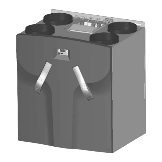
2 Per l’installatore ComfoAir confi gurazione Il ComfoAir è composto normalmente da: • Involucro esterno rivestito (A); • Interno (B) in polipropilene espanso di alta qualità (E)PP; • 4 allacciamenti (C) per i condotti dell’aria. • 2 materiali fi ltranti (D) per la depurazione dell’aria. Categoria fi ltro: aria esterna G3, aria di ritorno G3; •... -
Seite 7: Dati Tecnici
Dati tecnici ComfoAir 550 (posizione nL) Posizione Capacità di ventilazione Energia 50 m3/h con 5 Pa 13 W OSIZIONE ASSENTE 150 m3/h con 50 Pa 30 W OSIZIONE BASSA 225 m3/h con 100 Pa 69 W OSIZIONE MEDIA 330 m3/h con 215 Pa... - Seite 8 Dati tecnici ComfoAir 550 (posizione HL) Posizione Capacità di ventilazione Energia 50 m3/h con 5 Pa 13 W OSIZIONE ASSENTE 180 m3/h con 60 Pa 41 W OSIZIONE BASSA 330 m3/h con 215 Pa 160 W OSIZIONE MEDIA 430 m3/h con 360 Pa...
-
Seite 9: Disegno Quotato
Disegno quotato DATI ELETTRICI E COLLEGAMENTO 724.5 208.5 208.5 ø 32 SCARICO CONDENSA SCARICO CONDENSA DESTRO SINISTRO... -
Seite 10: Condizioni Di Installazione
Matricola (come il bagno o WC). Questo consentirà di ComfoAir 550 L ComfoAir 550 R evitare la condensa sulla superfi cie esterna ComfoAir 550 L RF ComfoAir 550 R RF del ComfoAir. • Nell’ambiente scelto per l’installazione devono Signifi cato delle lettere: essere presenti le seguenti strutture: •... -
Seite 11: Montaggio Del Comfoair
Zehnder. Qualsiasi altro condotto fl essibile an- Per il montaggio su altre pareti consigliamo utilizza- nullerà le funzioni di base del sistema di venti- re il supporto di montaggio a pavimento di Zehnder lazione bilanciata. (da richiedere come opzione). Questo accorgimento •... -
Seite 12: Allacciamento Dello Scarico Condensa
2.6.3 Allacciamento dello scarico condensa Messa in servizio del ComfoAir Dopo l'installazione il ComfoAir deve essere messo in servizio. La messa in servizio può essere effettuata dai menu P del dispositivo di funzionamento digitale. In questi menu P è possibile scegliere diverse impostazioni per il ComfoAir (ovvero le regolazioni della ventila- zione). -
Seite 13: Display Sull'unità
L'utente può accedere ai menu P - P1, P2 e P9 - Accesso ai menu principalmente per verifi care gli stati e impostare i valori di ritardo. I restanti menu P, da P3 a P8, sono Sequenza Premere tasto Display Descrizione destinati esclusivamente all’installatore. -
Seite 14: Menu P Per L'utente
2.7.2 Menu P per l’utente Menu P1 Stato delle regolazioni Stato Sottome- Descrizione Attivato Menu 21 attivo in questo momento? Sì (1) / No (0) Menu 22 attivo in questo momento? Sì (1) / No (0) Menu 23 attivo in questo momento? Sì... -
Seite 15: Menu P Per L'installatore
Valori di ritardo Sottomenu Descrizione Minimo Massimo Reset Ritardo di disattivazione per la posizio- 1 Min. 120 Min. 30 Min. ne di ventilazione 3 " ". Nota: Applicabile solo • Dopo aver premuto a lungo “ ” alle installazioni con interrut- (>2 sec.), il ComfoAir passa per ‘x’... - Seite 16 Valore corrente della T2 Effettivi (= temperatura aria di immissione) Valore corrente della T3 Effettivi (= temperatura aria di ritorno) Valore corrente della T4 Effettivi (= temperatura aria di scarico) Menu P5 Impostazione delle regolazioni aggiuntive Valori regolazioni aggiuntive Sottomenu Descrizione Minimo...
- Seite 17 Valori regolazioni aggiuntive Sottomenu Descrizione Minimo Massimo Reset Indicare la presenza di uno scambiatore entalpico. 0 (= no) 2 (= sì) • 0; Lo scambiatore entalpico è assente • 1; Lo scambiatore entalpico è presente con sensore • 2; Lo scambiatore entalpico è presente senza senso- re RH Verifi...
- Seite 18 Menu P8 Impostazione degli RF ingresso e ingresso analogico (0-10V) Valori informazioni (di errore) N. seq. Descrizione Minimo Massimo Reset Ingresso RF 1 0 = assente 1 = presente 0 = azionare 1 = regolare (ingresso RF1) valore di riferimento ingresso RF 1 (regolare) impostazione min.
-
Seite 19: Regolazione Delle Specifi Che Di Ventilazione
2.8 Regolazione delle specifi che di ventilazione Dopo l’installazione il ComfoAir deve essere regolato. Le regolazioni possono essere effettuate dalle sud- 5 Controllare che entrambi i ventilatori funzionino dette specifi che di ventilazione del ComfoAir. alle tre velocità. Le impostazioni standard del ComfoAir, nL, sono: 6 Commutare il ComfoAir su alta velocità. -
Seite 20: Manutenzione Per L'installatore
Quando si effettua il riassemblaggio del Per impostare i ventilatori, utilizzare il gra- fi co con le specifi che di circolazione del pannello anteriore, la sezione inferiore ComfoAir. deve essere innanzitutto inserita dietro al bordo rialzato per garantire una buona Qualora i volumi d'aria ora impostati dovesse- tenuta. -
Seite 21: Ispezione Dei Ventilatori
Risciacquare lo scambiatore con acqua calda 2.9.2 Ispezione dello dei ventilatori pulita di rubinetto (max. 40 Tenere lo scambiatore con due mani usando le Controllare i ventilatori 1 volta ogni due anni superfi ci laterali colorate e scuoterlo bene per far fuoriuscire l’acqua in eccesso. -
Seite 22: Pulizia Fi Ltro In Presenza Di Un Dispositivo Antigelo (Opzionale)
2.9.3 Pulizia fi ltro in presenza di un 2.10 Guasti L’eventuale presenza di guasti al ComfoAir viene dispositivo antigelo comunicata nei seguenti modi: • Il messaggio di errore appare sul display del Il fi ltro del dispositivo antigelo (se presente) ComfoAir. -
Seite 23: Interrruttore A 3 Posizioni Con Indicazione Del Guasto
2.10.2 Interruttore a 3 posizioni con indicazione del guasto Gli interruttori a 3 posizioni che dispongono di un in- dicatore di errore, in caso di guasto o di fi ltro sporco ne indicano immediatamente la presenza. A secon- da del tipo di interruttore a 3 posizioni, la comunica- zione avviene nei seguenti due modi: •... -
Seite 24: Cosa Fare In Caso Di Guasto / Guida Alla Risoluzione Dei Guasti
2.10.3 Cosa fare in caso di guasto / Guida alla risoluzione dei guasti Di seguito vengono fornite indicazioni relative ai messaggi di errore che possono essere visualizzati sul display digitale in caso di guasti. A1 / A2 / A3 / A4 Il sensore NTC T1 / T2 / T3 / T4 è... - Seite 25 A5 / Guasto al motore del bypass / preriscaldatore. Rimuovere le maniglie dal ComfoAir. Rimuovere i filtri dal ComfoAir. Allentare il pannello anteriore rimuovendo le viti. Far scorrere il pannello anteriore verso l'alto e rimuoverlo dal ComfoAir. Allentare il coperchio sigillato rimuovendo le viti.
- Seite 26 Questo messaggio di erro- Preriscaldatore non re appare se la temperatu- riscalda a sufficienza. ra di T1 aumenta di meno di 4°C tre minuti dopo l’accensione del preriscal- P51 e P57 datore. È anche possibile sono impostati che nel preriscaldatore sul valore scorra troppa aria fredda.
- Seite 27 Il preriscaldatore si surriscalda. (T1 > 40ºC) Rimuovere le maniglie dal ComfoAir. Rimuovere i filtri dal ComfoAir. Rimuovere i filtri dal ComfoAir. Far scorrere il pannello anteriore verso l'alto e rimuoverlo dal ComfoAir. Allentare il coperchio sigillato r imuovendo le viti. Allentare il coperchio Tensione elettrica sigillato rimuovendo le viti.
- Seite 28 Guasto Impostare P60 su "0" Ripristinare l'unità (P74 su 1) EA2 Assenza di comunicazione tra il sensore di entalpia e il ComfoAir. È uno scambiatore entalpico a disposizione? Impostare P59 su "0" Impostare P59 su "2" Ripristinare l'unità Ripristinare l'unità (P74 su 1) (P74 au 1) ,Fil',tEr' Il filtro...
- Seite 29 E1 / Il ventilatore di immissione / scarico non gira Rimuovere le maniglie dal ComfoAir. Rimuovere i filtri dal ComfoAir. Allentare il pannello anteriore rimuovendo le viti. Far scorrere il pannello anteriore verso l'alto e rimuoverlo dal ComfoAir. Allentare il coperchio sigillato rimuovendo le viti.
-
Seite 30: Guasti (O Problemi) Senza Messaggio
2.10.4 Guasti (o problemi) senza messaggio Di seguito presentiamo una panoramica dei guasti (o problemi) che non sono accompagnati da messaggi. Problema/Guasto Indicazione Controllo / operazione È tutto spento Alimentazione presente Controllare il fusibile sul circuito stam- pato. • Sostituire il fusibile se è guasto. •... -
Seite 31: Parti Di Ricambio
2.11 Parti di ricambio Di seguito presentiamo una panoramica delle parti di ricambio disponibili per il ComfoAir. Numero Componente Numero articolo Ventilatori (sinistra e destra) 400200015 Servomotore e cavo (per il bypass e il dispositivo antigelo) 400300024 Sensore di temperatura T1 / T3 (in alto sull'apparecchio; 400300025 vicino al carrello elettronico). -
Seite 32: Schema Elettrico: Comfoair 550 Base - Modello Sinistro
2.12 Schema elettrico: ComfoAir 550 Base – Modello SINISTRO MANTELLO Marrone Marrone VENT. VENT. Dispositivo antigelo DISPLAY Bianco ( Blu (-) Giallo(0-10V) Giallo (0-10V) Blu (-) Bianco Marrone Marrone Bianco Bianco Marrone Marrone Bianco Bianco Rosso Nero Nero Rosso Valvola del bypass... -
Seite 33: Schema Elettrico: Comfoair 550 Base - Modello Destro
2.13 Schema elettrico: ComfoAir 550 Base – Modello DESTRO MANTELLO Marrone Marrone VENT. VENT. Dispositivo antigelo DISPLAY Bianco ( Blu (-) Giallo(0-10V) Giallo (0-10V) Blu (-) Bianco Marrone Marrone Bianco Bianco Marrone Marrone Bianco Bianco Rosso Nero Nero Rosso Valvola del bypass... -
Seite 34: Dichiarazione Ce Di Conformità
Tel.: +31 (0)38-4296911 Fax: +31 (0)38-4225694 Registro delle imprese di Zwolle 05022293 Dichiarazione CE di conformità Descrizione della macchina : Unità di recupero calore: ComfoAir 550 serie : Direttiva macchine (2006/42/CEE) Conforme con le direttive Direttiva Bassa tensione (2006/95/CEE) Direttiva EMC... - Seite 35 Alle Rechte vorbehalten. Die Zusammenstellung dieser Anleitung ist mit grösster Sorgfalt erfolgt. Dennoch haftet der Herausgeber nicht für Schäden aufgrund von fehlenden oder nicht korrekten Angaben in dieser Anleitung.
- Seite 36 2.10.3 Was im Falle einer Störung zu tun? / Störungsübersicht ............ 21 2.10.4 Störungen (oder Probleme) ohne Meldung ................27 2.11 Ersatzteile ............................28 2.12 Schaltplan: ComfoAir 550 Basic – LINKSSEITIGE Ausführung ............29 2.13 Schaltplan: ComfoAir 550 Basic – RECHTSSEITIGE Ausführung ............ 30 2.14 EWG-Konformitätserklärung ......................31...
-
Seite 37: Vorwort
Garantieansprüche zur sicheren und optimalen Installation und War- können ausschliesslich für Material- und/oder Kon- tung des ComfoAir 550 . Weiters soll sie Ihnen als struktionsfehler, die im Garantiezeitraum aufgetre- Nachschlagewerk bei Service- und Wartungsarbei- ten sind, geltend gemacht werden. Im Falle eines ten dienen, um diese auch mit größter Sorgfalt dur-... -
Seite 38: Sicherheit
1.2 Sicherheit 1.2.2 Sicherheitsvorrichtungen und Massnahmen • Der ComfoAir kann nicht ohne Werkzeug geöff- 1.2.1 Sicherheitsvorschriften Beachten Sie jederzeit die Sicherheitsvorschriften net werden; in dieser Anleitung. Bei Nichtbeachtung der Si- • Es muss ausgeschlossen sein, dass die Venti- cherheitsvorschriften und Anweisungen sowie der latoren mit der Hand berührt werden können. -
Seite 39: Comfoair Konfi Guration
Hinweise für den Installateur ComfoAir Konfi guration Der ComfoAir besteht serienmässig aus den folgenden Bauteilen: • Aussengehäuse (A) aus beschichtetem Stahlblech; • Innenraum (B) aus hochwertigem expandierten Polypropylen (E)PP; • 4 Anschlüsse (C) für die Luftreinigung. • 2 Filtertücher (D) für die Luftfi lterung. Filterklasse: Außenluft G3, Rückluft G3; •... -
Seite 40: Technische Spezifi Kationen
2.2 Technische Spezifi kationen ComfoAir 550 (Stufe nL) Stufe Belüftungsleistung Leistung 50 m3/h bei 5 Pa 13 W TUFE BWESEND 150 m3/h bei 50 Pa 30 W TUFE NIEDRIG 225 m3/h bei 100 Pa 69 W TUFE MITTEL 330 m3/h bei 215 Pa... - Seite 41 ComfoAir 550 (Stufe HL) Stufe Belüftungsleistung Leistung 50 m3/h bei 5 Pa 13 W TUFE BWESEND 180 m3/h bei 60 Pa 41 W TUFE NIEDRIG 330 m3/h bei 215 Pa 160 W TUFE MITTEL 430 m3/h bei 360 Pa 310 W...
-
Seite 42: Massskizze
Massskizze KABELDURCHFÜHRUNG STROMANSCHLUSS UND KABELDATEN. 724.5 208.5 208.5 ø32 KONDENSATABLAUF KONDENSATABLAUF ComfoAir RECHTS ComfoAir LINKS... -
Seite 43: Installationsvoraussetzungen
Im Raum müssen die folgenden Vorrichtungen ComfoAir 550 L vorhanden sein: ComfoAir 550 R Luftkanalanschlüsse. 230 V Netzanschluss. ComfoAir 550 L RF Anschluss für den Kondensatablauf. ComfoAir 550 R RF Anschluss eines drahtgebundenen 3-Stu- fenschalters (optional). Bedeutung der Zusätze: •... -
Seite 44: Montage Des Comfoair
Masse von mindestens 200 kg/m Zehnder zulässig. Flexible Kanäle anderer Für andere Wände empfehlen wir, den Monta- Hersteller behindern die grundsätzliche gesockel von Zehnder zur Aufstellung auf dem Funktion des Belüftungssystems. Boden zu verwenden (als Option erhältlich). Auf •... -
Seite 45: Anschluss Der Kondensatablauf
2.6.3 Anschluss des Kondensatablaufs Inbetriebnahme des ComfoAir Der ComfoAir kann nach der Installation in Betrieb genommen werden. Die Inbetriebnahme kann mit den P-Menüs über das digitale Bediengerät erfolgen. In diesen P-Menüs können verschiedene Einstellungen (vor allem Belüftungsregelungen) für den ComfoAir gewählt werden. -
Seite 46: Zugang Zu Den Menüs
Zugang zu den Menüs Reihen- Drucktasten Display Bezeichnung folge MENU Zeitverzögerungen ▲ + ▼ Tasten gleichzeitig (3 Sekunden) drücken ▲ Temperaturen ▲ Regelungen ▲ Regelungen ▲ Störung / Reset / Selbsttest ▲ 0 - 10 V-Eingänge ▲ Statusanzeige Einstellbeispiel Der Leistung des Zuluftventilators in DER MITTLEREN STUFE auf 40% einstellen Reihen- Drucktasten... -
Seite 47: P-Menüs Für Den Benutzer
2.7.2 P-Menüs für den Benutzer Menü P1 Status der Regelungen Status Submenü Bezeichnung Aktiviert Menü 21 zurzeit aktiv? Ja (1) / Nein (0) Menü 22 zurzeit aktiv? Ja (1) / Nein (0) Menü 23 zurzeit aktiv? Ja (1) / Nein (0) Menü... - Seite 48 Werte Zeitverzögerungen Submenü Bezeichnung Minimum Maxi- Voll- stän- diger Reset Ausschaltverzögerung für Belüf- 1 Min. 120 Min. 30 Min. tungsstufe 3 " ". • Der ComfoAir schaltet nach lan- Hinweis: Nur für Anlagen mit einem RF-Schalter. gem Drücken (> 2 s) auf „ “, „x“...
-
Seite 49: P-Menüs Für Den Installateur
2.7.3 P-Menüs für den Installateur Menüs ohne Min- und Maxwert können nur ausgelesen aber nicht verändert werden. Menü P3 Belüftungsregelungen einstellen Werte Belüftungsregelungen Submenü Bezeichnung Minimum Maximum Vollständiger Reset N.v. 0% oder 15% 97% nL / HL 15% / 15% Leistung (in %) des Abluftventilators nL / HL 35% / 40%... - Seite 50 Menü P5 Einstellung von Zusatzregelungen Werte Zusatzregelungen Submenü Bezeichnung Minimum Maximum Vollständiger Reset Aktivierung der 0 (= Nein) 1 (= Ja) Kaminregelung. Vorhandensein eines 0 (= Nein) 1 (= Ja) Frostschutzelements angeben. Hinweis: Änderungen nur nach einem vollständigen Reset oder wenn nachträglich ein Vorwärmer installiert wurde vornehmen.
- Seite 51 Werte Zusatzregelungen Submenü Bezeichnung Minimum Maximum Vollständiger Reset Vorhandensein des Enthalpietau- 0 (= Nein) 2 (= Ja) schers angeben. • 0; kein Enthalpietauscher vorhan- • 1; Enthalpietauscher mit RH-Sen- sor vorhanden • 2; Enthalpietauscher ohne RH- Sensor vorhanden Überprüfen Sie, ob der Kondensatablauf luftdicht ist. Nur ein Enthalpietauscher ohne RH-Sensor kann werden eingesetzt.
- Seite 52 Selbsttest des ComfoAir (= Aktivieren) Hinweis: • Die LEDs auf dem Display beginnen zu blinken. • Der ComfoAir läuft mit maximaler Drehzahl (RPM). • Das Bypassventil öffnet und schließt. • Das Vorwärmerventil öffnet und schließt, nachdem das Bypassventil geschlossen hat (bei Vorhandensein eines Vorwärmers). Reset Zähler Filterverunreinigung (= Aktivieren) Hinweis:...
-
Seite 53: Einstellung Der Luftspezifi Kationen
Einstellung der Luftspezifi kationen Der ComfoAir muss nach der Installation eingestellt werden. Dies kann anhand der oben dargestellten Luftspezifi kationen des ComfoAir erfolgen. Die Standardeinstellungen des ComfoAir, nL, lauten wie folgt: 7. Platzieren Sie alle Ventile und stellen Sie die Stufe N IEDRIG Ventile gemäss den Anweisungen oder wie in... -
Seite 54: Pfl Ege Durch Den Installateur
9. Sollten die bisher eingestellten Luftmengen Bei der Montage der Dichtungsplatte noch zu viel abweichen: Stellen Sie die Ventile muss die Unterseite der Dichtungsplat- dann nach. 10. Kontrollieren Sie nach der Einstellung aller Ven- te erst hinter den aufstehenden Rand tilstufen noch einmal die gesamte Anlage. -
Seite 55: Inspektion Der Ventilatoren
Nur bei Standard Wärmetauschern mit grünem De- ckel und Enthalpietauscher mit blauem Deckel: a. Tauchen Sie den Wärmetauscher dazu einige Mal in warmes Wasser (max. 40 °C). b. Spülen Sie den Wärmetauscher anschlies- send gründlich mit warmem Leitungswasser ab (max. 40°C). c. -
Seite 56: Störungen
2.10.2 3-Stufenschalter mit Störungsmelder Die nach innen gewölbte (hohle) Seite des Die 3-Stufenschalter, die über einen Störungsmel- fi lter der Frostschutzelement muss zum der verfügen, geben beim Auftreten oder bei einer Halter des Frostschutzelement zeigen. Filtermeldung ein Störung ein Signal ab. Dieses er- folgt je nach Typ des 3-Stufenschalters auf eine der 11. -
Seite 57: Was Im Falle Einer Störung Zu Tun? / Störungsübersicht
2.10.3 Was im Falle einer Störung zu tun? / Störungsübersicht Im Folgenden geben wir Ihnen Hinweise für das Vorgehen bei den genannten Störungsmeldungen, die auf dem digitalen Gerät angezeigt werden. A1 / A2 / A3 / A4 NTC-Fühler T1 / T2 / T3 / T4 ist defekt. -
Seite 58: Elektrische Spannung
A5 / Störung am Motor von Bypass oder Vorwämer. Handgriffe aus dem ComfoAir ziehen. Filter aus dem ComfoAir ziehen. Lösen Sie die Front- platte, indem Sie die Schrauben entfernen. Schieben Sie die Front- platte hoch und nehmen Sie die Frontplatte des ComfoAir ab. - Seite 59 Diese Fehlermeldung wird Vorwärmer angezeigt, wenn die Tem- erhitzt nicht ausreichend. peratur von T1 drei Minu- ten nach Einschalten des Vorwärmers um weniger als 4 °C gestiegen ist. Es P51 und P57 auf korrekten ist auch möglich, dass zu Nein viel kalte Luft am Spannungsversorgung P51 und P57 auf kor-...
- Seite 60 Vorwärmer zu heiß. (T1 > 40 ºC) Handgriffe aus dem ComfoAir ziehen. Filter aus dem ComfoAir ziehen. Lösen Sie die Frontplatte, indem Sie die Schrauben entfernen. Schieben Sie die Frontplatte hoch und nehmen Sie die Front- platte des ComfoAir ab. Lösen Sie die Dichtungs- platte, indem Sie die Schrauben entfernen.
- Seite 61 Störung Gerät zurücksetzen (P74 auf 1) Keine Kommunikation zwischen Enthalpiesensor und ComfoAir. Ist ein Nein Enthalpietauscher vorhanden? P59 auf "0" stellen P59 auf "2" stellen Gerät zurücksetzen Gerät zurücksetzen (P74 auf 1) (P74 auf 1) ,Fil',tEr' Internes Filter verschmutzt Maximal 4 Sekunden auf OK auf dem Bildschirm drücken, bis die Warnung verschwindet.
- Seite 62 E1 / Zu-/Abluftventilator läuft nicht. Handgriffe aus dem ComfoAir ziehen. Filter aus dem ComfoAir ziehen. Lösen Sie die Front- platte, indem Sie die Schrauben entfernen. Schieben Sie die Front- platte hoch und nehmen Sie die Frontplatte des ComfoAir ab. Lösen Sie die Dichtungs- platte, indem Sie die Schrauben entfernen.
-
Seite 63: Störungen (Oder Probleme) Ohne Meldung
2.10.4 Störungen (oder Probleme) ohne Meldung Im Folgenden eine Übersicht über Störungen (oder Probleme), bei denen keine Meldung erscheint. Problem / Störung Ursache/Anzeichen Kontrolle / Maßnahme Alles aus Speisespannung Kontrollieren Sie die Sicherung auf der Steuerplatine. • Defekte Sicherungen tauschen. •... -
Seite 64: Ersatzteile
2.11 Ersatzteile Im Folgenden eine Übersicht der verfügbaren Ersatzteile für den ComfoAir. Nummer Teil Artikelnummer Ventilatoren (links und rechts) 400200015 Servomotor & kabel (für den Bypass und Frostschutzelement) 400300024 Temperaturfühler T1 / T3 (oben im Gerät, bei Elektronikschlitten) 400300025 Temperaturfühler T2 / T4 (in Schneckenhaus der beiden Ventilatoren) 400300026 Frostschutzelement 400300027... -
Seite 65: Schaltplan: Comfoair 550 Basic - Linksseitige Ausführung
2.12 Schaltplan: ComfoAir 550 Basic – LINKSSEITIGE Ausführung BEHUIZING Blau Braun Braun Blau Vorwärmer Weiß Blau Gelb Gelb Blau Weiß Braun Braun Weiß Weiß Braun Braun Weiß Weiß Schwarz Schwarz Bypassventil Vorwärmerventil Grün/Gelb Grün/Gelb Grün/Gelb... -
Seite 66: Schaltplan: Comfoair 550 Basic - Rechtsseitige Ausführung
2.13 Schaltplan: ComfoAir 550 Basic – RECHTSSEITIGE Ausführung GEHAÜSE Blau Braun Braun Blau Vorwärmer Weiß Blau Gelb Gelb Blau Weiß Braun Braun Weiß Weiß Braun Braun Weiß Weiß Schwarz Schwarz Vorwärmerventil Bypassventil Grün/Gelb Grün/Gelb Grün/Gelb... -
Seite 67: Ewg-Konformitätserklärung
Zehnder Group Nederland B.V. Lingenstraat 2 8028 PM Zwolle-NL Tel.: +31 (0)38-4296911 Fax: +31 (0)38-4225694 Handelsregister Zwolle 05022293 EWG-Konformitätserklärung Bezeichnung des Geräts : Wärmerückgewinnungsgeräte: ComfoAir 550 Serie : Maschinenrichtlinie (2006/42/EWG) Entspricht den Richtlinien Niederspannungsvorschrift (2006/95/EWG) EMC-Vorschrift (2004/108/EWG) Zwolle, 19 März, 2010 Zehnder Group Nederland B.V... - Seite 68 All rights reserved. This manual has been compiled with the utmost care. The publisher cannot be held liable for any damage caused as a result of missing or incorrect information in this manual. In case of dis putes the Dutch version of these instructions will be binding.
- Seite 69 2.10.4 Malfunctions (or problems) without alarms ................25 2.11 Service parts ............................26 2.12 Wiring diagram: ComfoAir 550 Basic – LEFT-HAND version ............27 2.13 Wiring diagram: ComfoAir 550 Basic – RIGHT-HAND version ............28 2.14 EEC declaration of conformity ......................29...
-
Seite 70: Preface
30 months after the date of manu- facture. Warranty claims may only be submitted for of the ComfoAir 550 . It is also intended as a re- material faults and/or construction faults arising ference for servicing, so that this can be carried out in a responsible manner. -
Seite 71: Safety
Safety 1.2.2 Safety provisions and measures • The ComfoAir cannot be opened without using tools; 1.2.1 Safety regulations • It should not be possible to touch the fans, Always comply with safety regulations in this ma- therefore ducting must be connected to the nual. -
Seite 72: For The Fitter
2 For the Fitter ComfoAir confi guration The standard ComfoAir confi guration consists of: • External casing (A) of coated sheeting; • Interior (B) of high-quality, expanded polypropylene (E)PP; • 4 connections (C) for the air ducts; • 2 cloth fi lters (D) for air purifi cation. Filter classifi cation: outside air G3, return air G3; •... -
Seite 73: Technical Specifi Cations
2.2 Technical specifi cations ComfoAir 550 (nL setting) Position Ventilation capacity Power 50 m3/h at 5 Pa 13 W BSENT ETTING 150 m3/h at 50 Pa 30 W ETTING 225 m3/h at 100 Pa 69 W EDIUM ETTING 330 m3/h at 215 Pa... - Seite 74 ComfoAir 550 (HL setting) Position Ventilation capacity Power 50 m3/h at 5 Pa 13 W BSENT ETTING 180 m3/h at 60 Pa 41 W ETTING 330 m3/h at 215 Pa 160 W EDIUM ETTING 430 m3/h at 360 Pa 310 W...
-
Seite 75: Dimension Sketch
Dimension sketch ELECTRICAL AND DATA CONNECTION 724.5 208.5 208.5 ø 32 CONDENSATION DRAIN CONDENSATION DRAIN LEFT-HAND VERSION RIGHT-HAND VERSION EN - 6... -
Seite 76: Installation Conditions
. For other types of wall, we re- • A gap should be left near the doors in order to commend using the Zehnder mounting frame on the ensure effective and draughtfree airfl ow in the fl oor (available as an optional extra). This reduces house. -
Seite 77: Connection Of The Air Ducts
Zehnder. Position the upper edge of the water seal at • When using fl exible channels only Zehnder • least 40 mm underneath the condensation channel systems may be used. Any other fl ex- drain of the ComfoAir. -
Seite 78: Commissioning The Comfoair
Commissioning the ComfoAir Access to the menus After installation, the ComfoAir must be commissio- Sequen- Press Display Description ned. MENU Time delay This can be done via the P menus on the digital Press the buttons operating device. These P menus can be used to (3 seconds) simultaneously. -
Seite 79: P Menus For The User
2.7.2 P menus for the user Menu P1 Status of programmes Status Sub- Description Activated menu Is menu 21 currently active? Yes (1) / No (0) Is menu 22 currently active? Yes (1) / No (0) Is menu 23 currently active? Yes (1) / No (0) Is menu 24 currently active? Yes (1) / No (0) -
Seite 80: P Menus For The Installer
Time delay values Sub-menu Description Minimum Maxi- General Reset Overrun timer for ventilation setting 3 " using 1 Min. 120 Min. 30 Min. ". Note: • After pressing " " (> 2 CONTINUOUSLY Only applies to systems fi t- sec.), the ComfoAir will switch to the HIGH ted with an RF switch. - Seite 81 Menu P4 Reading the temperatures Temperature values Submenu Description Minimum Maximum General Reset Comfort temperature Current value of T1 Current (= outside air temperature) Current value of T2 Current (= supply air temperature) Current value of T3 Current (= return air temperature) Current value of T4 Current (= exhaust air temperature)
- Seite 82 Additional programme values Submenu Description Minimum Maximum General Reset Confi rming the presence of an enthalpy exchanger. 0 (= No) 2 (= Yes) • 0; Enthalpy exchanger not fi tted • 1; Enthalpy exchanger with RH sensor. • 2; Enthalpy exchanger without RH sensor. Only a enthalpy exchanger without RH sensor can be fi...
-
Seite 83: Programming Air Specifi Cations
Menu P8 Setting the RF input and digital inputs (0-10V) Analogue input values Submenu Description Minimum Maximum General Reset RF input 1 0= not fi tted 1= fi tted 0= controlling 1= programming (RF input 1) 0 set point RF input 1 (programming) min. -
Seite 84: Maintenance By The Installer
This can be done using the air specifi cations of the Use the chart of the ComfoAir's air specifi ca- ComfoAir above. tions to set the fans. The default settings of the ComfoAir nL are: 9. In the event that the currently set air volumes still deviate too much: Adjust the valves. -
Seite 85: Inspecting And Cleaning The Fans
er can be washed with water. When having an Enthalpy exchanger with a white cover do never wash it with water. Do not use aggressive cleaning agents or solvents. If the fans or preheater element fi lter also need maintenance do not re-install the heat exchanger yet. -
Seite 86: Inspecting And Cleaning The Preheater Element Fi Lter
menu P76. 2.10 Malfunctions Malfunctions in the ComfoAir are reported as fol- lows: Fasten the screws to a maximum of 1.5 Nm. • The malfunction alert appears on the display. This is roughly equal to speed 2 of an aver- •... -
Seite 87: 3-Position Switches With Malfunction Indicator
2.10.2 3-position switch with malfunction indicators The 3-position switches that are fi tted with a mal- function indicator show when a malfunction or fi l- ter dirty alert has occurred. Depending on the type of the 3-position switch, this is done in one of the following two ways: •... -
Seite 88: What To Do In The Event Of A Malfunction / Trouble Shooting
2.10.3 What to do in the event of a malfunction / Trouble shooting Below are a number of trouble-shooting tips for the malfunction alerts described previously which can appear on the digital operating device in the event of a malfunction. A1 / A2 / A3 / A4 NTC sensor... - Seite 89 A5 / Malfunction in the bypass / preheater element motor Remove the handles from the ComfoAir. Remove the filters from the ComfoAir. Release the front panel by unscrewing the screws. Slide the front panel upwards and remove the front panel from the ComfoAir.
- Seite 90 This error will appear Preheater element when after 3 minutes of does not heat sufficiently. switching on the preheater element the temperature increase of T1 is less P51 and then 4ºC. This can also P57 set to happen when there is too the correct much cold air passing the value?
- Seite 91 Preheater element becomes too hot. º (T1 > 40 Remove the handles from the ComfoAir. Remove the filters from the ComfoAir. Release the front panel by unscrewing the screws. Slide the front panel upwards and remove the front panel from the ComfoAir.
- Seite 92 Malfunction Set P60 on "0". Reset the unit (P74 on 1) No communication between the enthalpy sensor and the ComfoAir Is an enthalpy exchanger present? Set P59 to '0' Set P59 to '2' Reset the unit Reset the unit (P74 on 1) (P74 on 1) ,Fil' ,tEr' Internal Filter is dirty...
- Seite 93 E1 / Supply fan / Exhaust fan not rotating Remove the handles from the ComfoAir. Remove the filters from the ComfoAir. Release the front panel by unscrewing the screws. Slide the front panel upwards and remove the front panel from the ComfoAir.
-
Seite 94: Malfunctions (Or Problems) Without Alarms
2.10.4 Malfunctions (or problems) without alerts An overview of the malfunctions (or problems) without notifi cations is given below. Problem/Malfunction Indication Check / action System switched off Power supply on Check the fuse on the control circuit board. • If the fuse is Defect, replace fuse. •... -
Seite 95: Service Parts
2.11 Service parts The following table contains an overview of the spare parts available for the ComfoAir. Number Part Art.nr. Fans (left and right) 400200015 Servo motor & cable (for the bypass and the pre-heater) 400300024 Temperature sensor T1 / T3 (in top of unit; near the electronic carriage) 400300025 Temperature sensor T2 / T4 (in scroll casing of both fans) 400300026... -
Seite 96: Wiring Diagram: Comfoair 550 Basic - Left-Hand Version
2.12 Wiring diagram: ComfoAir 550 Basic - LEFT-HAND version CASING Blue Brown Brown Blue Preheater malfunction indicator of wired 3-position switch White Blue Yellow Yellow Blue White Brown Brown White White Brown Brown White White Black Black Bypass valve Preheater valve... -
Seite 97: Wiring Diagram: Comfoair 550 Basic - Right-Hand Version
2.13 Wiring diagram: ComfoAir 550 Basic - RIGHT-HAND version CASING Blue Brown Brown Blue VENT. VENT. Preheater malfunction indicator of wired 3-position switch DISPLAY White ( Blue(-) Yellow (0-10V) Yellow (0-10V) Blue (-) White ( Brown Brown White White Brown... -
Seite 98: Eec Declaration Of Conformity
8028 PM Zwolle-NL Tel.: +31 (0)38-4296911 Fax: +31 (0)38-4225694 Company register Zwolle 05022293 EEC declaration of conformity Machine description : Heat recovery units: ComfoAir 550 series Complies with the following directives : Machinery Directive (2006/42/EEC) Low Voltage Directive (2006/95/EEC) EMC Directive... - Seite 99 31 - EN...
- Seite 100 Zehnder Tecnosystems S.r.l. Via XXV Luglio, 6 I - 41011 Campogalliano (MO) tel.: +39 (0)59 9786200 fax: +39 (0)59 9786201 Internet: www.comfosystems.it E-mail: info@comfosystems.it...