Herunterladen Inhalt Inhalt Diese Seite drucken
Carrier CCU Regelungshandbuch
Vorschau ausblenden Andere Handbücher für CCU:
Inhaltsverzeichnis

Werbung

Verfügbare Sprachen
  • DE

Verfügbare Sprachen

  • DEUTSCH, seite 79
M A N U E L
D E
R É G U L A T I O N
MANUEL DE RÉGULATION FR
CONTROL MANUAL EN
HANDBUCH FÜR DIE REGELUNG DE
IT
MANUAL DE REGULACIÓN
BEDIENINGSHANDLEIDING SP
INSTRUKCJA OBSŁUGI SYSTEMU STEROWANIA PL
Close control units
CARRIER CCU Controller
Notice originale

Werbung

Inhaltsverzeichnis
loading

Inhaltszusammenfassung für Carrier CCU

  • Seite 1 R É G U L A T I O N MANUEL DE RÉGULATION FR CONTROL MANUAL EN HANDBUCH FÜR DIE REGELUNG DE MANUAL DE REGULACIÓN BEDIENINGSHANDLEIDING SP INSTRUKCJA OBSŁUGI SYSTEMU STEROWANIA PL Close control units CARRIER CCU Controller Notice originale...
  • Seite 2: Inhaltsverzeichnis

    SOMMAIRE 1 - GENERALITES ....................................3 2 - COMPOSITION ....................................4 2.1 - Sur la face avant : ..................................4 2.2 - Sur la face arrière : ..................................5 3 - ARBORESCENCE DES MENUS ..............................8 4 - NIVEAU D'ACCES (MENU 8) ..............................11 5 - CONFIGURATION DU NOMBRE D'UNITES ..........................
  • Seite 3: Generalites

    1 - GENERALITES Le régulateur CCU CONTROLLER équipe en option standard les systèmes Close Control Unit. Pupitre de réglage et de signalisation  muni  d’un  afficheur  LCD  (160  caractères).  Le  régulateur  CCU CONTROLLER  est  équipé  d’un  microprocesseur  et  d’une  carte  additionnelle pour assurer les fonctions suivantes :  ■ Filtration Contrôle de la perte de charge des filtres avec surveillance de la présence de débit d’air et de l’encrassement.  ■ Asservissement (Mode Refroidissement) • Modèle eau glacée : Ouverture progressive de la vanne 3 voies sur élévation de la température.  • Modèle détente directe : Enclenchement d'un ou plusieurs étages frigorifiques sur élévation de la température. (Action sur groupe de condensation).
  • Seite 4: Composition

    7 - Validation 8 -  Correction  9 -  Valeurs consignes 10 - Ecran LCD 160 caractères Le  dialogue  entre  les  machines  et  l’utilisateur  est  assuré  par  des  messages  de  textes  simples  et  précis  sur  un  écran  LCD  à  160  caractères. Le CCU CONTROLLER affiche automatiquement des informations propres au fonctionnement du groupe. (ExempleApparition d’un défaut).  Il est composé de :  - Un écran à cristaux rétro éclairés de 4 lignes de 40 caractères.  - Un bouton poussoir d’autorisation de marche ou arrêt forcé, équipé d’une Led de signalisation (Led verte). • Led verte éteinte → unité à l'arrȇt.
  • Seite 5: Sur La Face Arrière

    2 - COMPOSITION NOTA : Le texte qui suit le numéro de l’unité indique son état de fonctionnement. La première ligne est simplement un affichage de la date et de l’heure. Nous accédons à ce menu principal par la touche numérique  ‘’0’’ à partir de n’importe quel affichage. Déplacer le curseur à l’aide du pavé directionnel en face de la ligne correspondant aux informations voulues et taper "ENTRER".  La ligne ‘’CONFIGURATION NOMBRE D’UNITES’’ permet de configurer le fonctionnement en des unités raccordées sur le bus.  Les lignes ‘’UNITE…’’permettent d’interroger la machine.  Pour revenir au menu principal appuyer plusieurs fois sur la touche numérique ‘’0’’.  ■ Verrouillage du clavier Le régulateur peut être verrouillé ou déverrouillé en appuyant simultanément sur les touches “flèche droite” et “flèche gauche” pendant  5 secondes. Lorsque le régulateur est vérouillé, l'utilisateur peut consulté les informations mais ne pas modifier les réglages. 2.2 - Sur la face arrière : Les différents connecteurs permettant de relier les différents éléments nécessaire au pilotage de l'unité. ■...
  • Seite 6 2 - COMPOSITION ■ Désignation des borniers EA = Entrées Analogiques EL = Entrées Logiques  SA = Sorties Analogiques SL = Sorties Logiques BORNIER CCU Controller Sonde de la température à réguler (10K Ω) 0 V Sonde de la température de limitation de soufflage (10K Ω) Sonde de l'humidité relative à réguler (0 - 10V) (EA) 0 V Sonde de contrôle, de la pression différentielle sur le filtre (0-10V ou 0.5 - 4.5V) +12 V Commande à distance  Détection incendie / Sécurité extérieure Retour marche ventilateur de soufflage  Thermostat de sécurité de la batterie électrique électrique à réarmement manuel (EL) Défaut ou entretien de l'humidificateur Fuite d'eau Commun entrée logique Synthèse des défauts du groupe de condensation circuit 1 Décalage consigne température...
  • Seite 7 2 - COMPOSITION BORNIER CCU Controller Commande groupe de condensation 1 Commun étage frigorifique n° 1 (SL) Commande groupe de condensation 2 Commun étage frigorifique n°2 Commande de l'étage 1 de la batterie électrique Commande de l'étage 2 de la batterie électrique Commun commande batterie électrique  (SL) Commande du ventilateur de soufflage  Non utilisé Commun commande ventilateur  Alimentation 24VAC Alimentation 24VAC 0 V RS485 A ou + (Liaison entre régulateurs pour fonction maître / esclave) RS485 B ou - (Liaison entre régulateurs pour fonction maître / esclave) 0 V RS485 A ou + (Liaison avec GTC ou passerelle) RS485 B ou - (Liaison avec GTC ou passerelle) 0 V + 12 V RS485 A ou + (Liaison avec l'humidificateur CPY et/ou GMV) RS485 B ou - (Liaison avec l'humidificateur CPY et/ou GMV) 0 V 0 V Sonde de la température extérieure (10K Ω) Sonde de l'humidité relative extérieure (0 - 10 V) Sonde de contrôle de la pression différentielle en faux-plancher (0 - 10 V) (SA) Sonde de la pression différentielle ventilateur (0-10V) ou sonde température à réguler (2-10V) ou  pourcentage demandé sur signal externe (2-10V) COMMUTATEUR COM - COM 1 : résistance de fin de ligne sur liaison GTC (voir chapitre 13)
  • Seite 8: Arborescence Des Menus

    3 - ARBORESCENCE DES MENUS Suivant la configuration, seuls les menus utilisés sont affichés. L U N 1 0 / 0 4 / 2 0 1 7 0 9 H 3 0 S Y S T E M E C C U . C C O N F I G U R A T I O N N O M B R E D ' U N I T E S U N I T E...
  • Seite 9 3 - ARBORESCENCE DES MENUS Unité 1 Sans défaut, indication de la température, de  ENTER 1 Infos marche ENTER l'hygrométrie, des consignes, de l'état de l'unité et  de l'état de l'unité sur la liaison maitre/esclave Avec défaut, indication du type du défaut avec le  remède(BP reset pour annuler après réparation) Retour menu ENTER Liste des 20 derniers défauts horodatés. Pour avoir  2 Mémoire défaut l'état de la machine à l'instant du défaut, sélectionner  le défaut avec les surseurs et faire ENTER Retour menu 3.1 Type  3 Paramètres ENTER d'appareil 3.2 Régulation et ...
  • Seite 10 3 - ARBORESCENCE DES MENUS 20 pas de programmation  5.1 Marche ventilation 5 Programmation horloge ENTER pour marche ventilateur 20 pas de programmation horaire  5.2 Décalage consigne pour décalage consigne Retour menu 6 Niveau défaut ENTER Sélection pour repport des défauts sur  les relais défauts simple ou important Retour menu P700 7 Communication ENTER Configuration de la communication P706 Retour menu 8 Niveau d'accès ENTER 8.1 Accès niveau 1 Pour changement du niveau  8.2 Accès niveau 2 d'accès 8.3 Accès niveau 3 Retour menu...
  • Seite 11: Niveau D'acces (Menu 8)

    Retour menu 4 - NIVEAU D'ACCES (MENU 8) La  régulation  CCU  Controller  possède  3  niveaux  d’accès  dont  2  nécessitant  un  code.  L'accès  aux  différents  niveaux  se  fait  par  l'utilisation du menu 8 dans le menu de l’unité. ■ Accès au niveau 1 (Pas de code d'accès) Il s'agit du niveau général destiné à l'utilisateur final. Ce niveau permet d'accéder à tous les paramètres de lecture et aux réglages ...
  • Seite 12: Configuration Du Nombre D'unites

    5 - CONFIGURATION DU NOMBRE D'UNITES Ces paramètres sont visibles seulement si le paramètre P215 = 1 (unité maître) Ce sous-menu regroupe les paramètres de fonctionnement des unités. Elles peuvent fonctionner individuellement ou regroupées en  maître/esclaves. Niveau d'accès N° Désignation Réglage Par défaut Condition d'affichage CONFIGURATION DE FONCTIONNEMENT 1 à 32 : en unités indépendantes C01 Nombre d'unité 2 à 10 : en maitre/esclave 0 : Pas d'unité en complément C02 Unité en complément C01 > 1 et C01 < 11 1 : Une unité en complément 0 : Pas d'unité en secours...
  • Seite 13 5 - CONFIGURATION DU NOMBRE D'UNITES ARBORESCENCE DE LA CONFIGURATION DU NOMBRE D’UNITES (visible seulement si le paramètre P215 = 1 "unité maitre") Nombre d'unité Pas de secours Pas de complément Secours L'unité en complément Complément sert de secours Une unité en complément secour Une unité en secours Français Anglais Allemand Pas de rotation Espagnol Rotation automatique Temporisation de rotation Déverrouillé Relance périodique Verrouillé Nb de jours entre 2 relances Heure de relance Durée de la relance Décalage consigne froid Consigne d'enclenchement ...
  • Seite 14: Configuration De L'unite

    6 - CONFIGURATION DE L’UNITE 6.1 - Paramètres de l’unité 6.1.1 - TYPE D’APPAREIL (sous-menu 3.1) Afin  de  limiter  la  multiplication  des  logiciels  tout  en  répondant  aux  besoins  des  applications  rencontrées  chez  nos  clients,  CCU CONTROLLER est doté d'un système de paramètrages. Il permet de configurer la composition de l'unité ainsi que toutes les fonctions  qui devront être gérées par le système Pour paramètrer CCU CONTROLLER, utiliser le menu N°3 : PARAMETRE et le sous menu N°3.1 : TYPE D’APPAREIL. (Menu sur  l’affichage de CCU CONTROLLER) ...
  • Seite 15 6 - CONFIGURATION DE L’UNITE Niveau d'accès N° Désignation Réglage Par défaut Condition d'affichage CHOIX DE LA REGULATION 0 : Pas régulation en chauffage 1 : Une batterie de chauffage à eau Régulation en chauffage 2 : Une batterie de chauffage électrique 3  :  Batterie  électrique  ou  batterie  eau  chaude par contact 0 : Pas de régulation en déshumidification Régulation en déshumidification 1 : Une batterie à eau glacée 2 : Un système de détente directe 0 : Pas de régulation en humidification Réguration en humidification 2 : Progressive MODBUS 0 = Sans  Régulation en free-cooling P07 > 0 1 = Avec CONFIGURATION DES ECHANGEURS 1 : Une sortie tout ou rien (un étage)
  • Seite 16 6 - CONFIGURATION DE L’UNITE Niveau d'accès N° Désignation Réglage Par défaut Condition d'affichage VERROUILLAGE 0 : Configuration déverrouillée (L'unité  ne  peut  pas  démarrer,  les  paramètres  type  d'appareil  peuvent  être  modifiés). 1 : Configuration verrouillée Verrouillage de la configuration (L'unité peut démarrer après avoir appuyé  sur  le  bouton  poussoir"Marche/Arrêt"  du  pupitre. Les paramètres de type d'appareil  ne peuvent plus être modifiés. Le nombre  de déverrouillage est comptabilisé.) (*) Sur modification de ces paramètres lancement d'une séquence pour la paramètrage des GMV. 6.1.2 - REGULATION ET REGLAGES (sous-menu 3.2) Niveau d'accès N°...
  • Seite 17 6 - CONFIGURATION DE L’UNITE Niveau d'accès N° Désignation Réglage Par défaut Condition d'affichage REGULATION EN FREE-COOLING Différentiel enclenchement 3 à 20 K 3 K P11 = 1 free-cooling Consigne limite basse  -5 à 20 °C 0 °C P11 = 1 enclenchement free-cooling Limitation ouverture free-cooling 0 à 100 % 100 % P11 = 1 P11 = 1 et Consigne limite basse en poids  0 à 15 g 4 g (P09>0 ou  d'eau extérieure P10>0) P11 = 1 et Consigne limite hausse en ...
  • Seite 18 6 - CONFIGURATION DE L’UNITE Niveau d'accès N° Désignation Réglage Par défaut Condition d'affichage CONTROLE DES FILTRES Les valeurs correspondent au débit d'air maximum de l'appareil. En cas de variation de la vitesse du ventilateur, ces valeurs sont diminuées de façon proportionnelle Consigne de la pression  différentielle d'indication de la 10 à 80 Pa 30 Pa P02 ≠ 17 présence de débit d'air Consigne de la pression  différentielle d'indication 60 à 500 Pa 150 Pa d'encrassement du filtre Consigne de la pression  différentielle d'indication du filtre  100 à 550 Pa 190 Pa bouché CONTROLE DU DEBIT D'AIR Limite basse débit d'air 0 à MIN(P146,10000) 4000m³/h P02 = 17...
  • Seite 19 8,0 à 45,0 si P08>0 25,0°C P07 > 0 et P207 = 2 sur défaut sonde 2-10V Consigne température en chaud  MAX (8,P212) à 45,0°C si P07>0 20,0°C P08 > 0 et P207 = 2 sur défaut sonde 2-10V BUS MAITRE/ESCLAVE Numéro de l'unité sur le pupitre 1 à 32 6.1.3 - Paramètres de lecture (sous-menu 3.3) Ce troisième sous menu donne accès à toutes les valeurs (températures, humidités relatives, pressions, temporisations, compteurs,  états des entrée et sorties, etc) gérées par CCU CONTROLLER.. Seuls les paramètres utiles sont affichés. Ils ne peuvent pas être  modifiés  Les compteurs peuvent être remis à zéro. Pour cela, placer le curseur sur le compteur choisi, appuyer simultanément sur les touches  Reset et 0 pendant 5 à 6 secondes.  Tous ces paramètres sont accessibles au niveau accès “client”.  Niveau d'accès N° Désignation Unité Condition d'affichage CONSIGNE CALCULEE Valeur de la consigne en refroidissement  °C P07 > 0 Valeur de la consigne de la température en chauffage ...
  • Seite 20 Compteur horaire de l'indication des défauts simples ETAT DES COMMANDES DU VENTILATEUR Demande de marche de ventilateur Off/on P01 = 2 Demande de décalage de la consigne de température  Off/On P31 = 2 ou P32 = 2 DECOMPTE DE TEMPORISATION Mise en régime Temporisation d'enclenchement des étages de compresseurs P17 = 3 ou 4 NUMERO DE VERSION Numéro de version du soft du CCU CONTROLLER TEMPERATURE POUR REGULATION Température mesurée par le régulateur °C P207 = 1 et P207=2 Température reçue par Modbus °C P207 = 1 Température mesurée sur entrée 2-10V °C (P07>0 ou P08>0) et P207=2 pourcentage sur signal externe (P07>0 et P08=0) et P207=3 NUMERO DE COMMANDE Numéro de commande SO...
  • Seite 21: Paramètres De L'humidificateur (Visible Si P10 = 2)

    6 - CONFIGURATION DE L’UNITE 6.2 - Paramètres de l’humidificateur (visible si P10 = 2) 6.2.1 - Réglages (sous-menu 9.1) Niveau d'accès N° Désignation Réglage Par défaut Condition d'affichage Production maximale 20 à 100 % 100 % P10 = 2 Temps de retard en arrêt  0 s à120 s 0 s P10 = 2 Conductivité de l'eau (0 = mesure automatique > 0 =  0 à 125µS/cm 0 µS/cm P10 = 2...
  • Seite 22: Paramètres Des Ventilateurs De Soufflage (Visible Si P05 = 1 Ou 2 Ou 3)

    6 - CONFIGURATION DE L’UNITE 6.2.3 - Alarme (sous-menu 9.3) Alarme Désignation L'humidificateur n'a pas de défaut Remplacer le cylindre Conductivité de l'eau trop élevée Erreur paramètre de configuration Erreur mémoire interne Surintensité électrode Faible débit de vapeur pendant production réduite Niveau d'eau élevé sans demande d'humidification Manque d'eau alimentation Problème de vidange  Pour acquiter un défaut sur l’humidificateur il faut être dans le menu « ALARME » (menu 9.3) et appuyer sur la touche «...
  • Seite 23 6 - CONFIGURATION DE L’UNITE 6.3.2 - Informations GMV2 (sous-menu 10.2) Niveau d'accès N° Désignation Unité Condition d'affichage 1050 Vitesse maxi GMV2 tr/min P05 = 2 ou 3 1051 Vitesse demandée au GMV2  tr/min P05 = 2 ou 3 1052 Vitesse actuelle du GMV2 tr/min P05 = 2 ou 3 1053 Intensité consommée GMV2 P05 = 2 ou 3  1054 Tension alimentation crète GMV2 P05 = 2 ou 3  1055 Puissance absorbée GMV2 P05 = 2 ou 3 1060 Synthèse défaut GMV2 Off/On P05 = 2 ou 3...
  • Seite 24: Niveau Des Defauts (Menu 6)

    7 - NIVEAU DES DEFAUTS (MENU 6) Chaque type de défauts peut être reporté sur un des 2 relais à contacts inverseurs suivant : - Relais défaut simple. - Relais défaut important. Ce menu permet de paramétrer vers quel relais, simple ou important, le type de défaut sera reporter. N° Désignation Réglage Unité Condition d'affichage 0 : Défaut simple N02 Absence débit d'air (*) 1 : Défaut important 0 : Défaut simple N03 Ventilateur (*) 1 : Défaut important  (Groupe de condensation  0 : Défaut simple Basse pression de chaque circuit P17 > 0 1 : Défaut important Haute pression ou disjonction de chaque circuit) 0 : Défaut simple N05 Filtration encrassée 1 : Défaut important  0 : Défaut simple N06 Filtration bouchée (*) 1 : Défaut important 0 : Défaut simple N07 Sondes de température (10KΩ)
  • Seite 25: Utilisation D'une Programmation Hebdomadaire

    8 - PROGRAMMATION HEBDOMADAIRE (MENU 5) 8.3 - Utilisation d'une programmation hebdomadaire Programme hebdomadaire P R O G R A M M E H O R L O G E M A R C H E V E N T I L A T I O N P R O G .
  • Seite 26: Sondes

    9 - REGULATION - Fonctionnement en mode free cooling Unités W (eau glacée) • Sonde Température air repris : Pilotage progressif des registres motorisés puis de la vanne 3 voies. • Sonde Température de soufflage : limitation de la vanne 3 voies puis du registre AIR NEUF. Unités X (détente directe) • Sonde Température air repris : Pilotage progressif des registres (groupes de condensation à l'arrêt). • Sonde Température de soufflage : Limitation registre AIR NEUF ■ Régulation de l'humidité relative dite à Réguler Elle est de type proportionnel ou proportionnel intégral.  - Régulation en déshumidification La régulation maître est augmentée si l’humidité relative dépasse la consigne. Cette valeur est découpée selon le paramètrage  (paramètre de type d’appareil) et dans l’ordre :  • A étage pour la commande du groupe de condensation. • Progressive pour la commande de la vanne à eau glacée.  • A étage pour l’indication du dépassement haut de l’humidité relative.  Selon la composition de l’unité en proportionnel pur, un écart peut subsister entre la consigne et la mesure même avec tous les éléments à 0. ...
  • Seite 27: Mise En Route

    L'unité  n'est  pas  commandée  par  le  marche/arrêt  (contact  ou  horloge).  L'unité  est  choisie  comme unité en complément ou en secours et elle est en relance périodique. • En défaut simple : L'unité considérée est sous-tension. Elle a au moins un défaut simple mais pas de défaut important. • En défaut important : L'unité considérée est sous-tension. Elle a au moins un défaut important. • En hors-tension : Le CCU CONTROLLER de l'unité considérée ne répond pas. Elle n'est pas sous-tension ou la liaison bus  est coupée. 11.2 - Information de marche de chaque unités (menu 1 ''info marche'') • Unité sans défaut La première ligne : affiche les valeurs mesurées par les sondes de température et/ou d'humidité relative à réguler.
  • Seite 28: Tableau Des Alarmes

    Arrêt production de froid diagnostic de la panne • Vérifier la bonne conception du siphon • Vérifier l'amorçage du siphon Débordement du bac • Vérifier le bon écoulement des condensats  Sonde de fuite Fuite d'eau  • Vérifier que le débit d'air n'est pas trop élevé d'eau Fuite batterie ou  • Rechercher la fuite et la colmater humidificateur Sonde de • Contrôler la sonde  Sonde température  • Vérifier le raccordement et la continuité du câble Plus de fonctionnement ou Eprom mémoire • Contacter le SAV CARRIER d'affichage  Défaut pile de la carte CPU  L'heure est incorrecte • Changer la pile  l'horloge ne fonctionne plus...
  • Seite 29 11 - MISE EN ROUTE Défauts Sources Causes Remèdes • Contrôler la sonde Sonde • Changer la sonde • Contrôler la stabilité de la régulation Sonde de Température basse Mauvais fonctionnement • Vérifier le fonctionnement de la vanne chaude ou de la batterie  température électrique Dérive en déshumidification • Charge interne insuffisante • Contrôler la sonde Sonde • Changer la sonde  Sonde de • Contrôler la stabilité de la régulation Température haute Mauvais fonctionnement température •   V érifier le fonctionnement de la vanne froide, des compresseurs Surcharge T °C du local • Revoir les charges du local • Contrôler la sonde  Sonde • Changer la sonde ...
  • Seite 30: Bus Pour Fonction Maitre/Esclave

    ENTRE LES DIFFERENTES UNITES CCU CONTROLLER MAITRE CCU CONTROLLER ESCLAVE COM2 COM2 CCU CONTROLLER ESCLAVE Câble multiconducteurs blindés  gainés  (blindage  par  tresse)  longueur entre le 1r et le dernier  CCU CONTROLLER : 1000 m 1 : Ligne A ou + 2 : Ligne B ou - 3 : Terre COM2 COM2 : Commutateur de polarisation du Bus - Unité maitre = ON - Unité Esclave = OFF 12.2 - Procédure d'adressage des unités A la première mise sous tension, toutes les cartes sont initialisées avec le paramètre P215 ‘’NUMERO DE L’UNITE SUR LE PUPITRE ‘’ ayant la valeur 1.
  • Seite 31: Bus Pour Raccordement A Une Gtc Rs485 Modbus

    COM1 CCU CONTROLLER : 1000m 1 : Ligne A ou + 2 : Ligne B ou - 3 : Terre Pour un fonctionnement correct,  la ligne doit être polarisée. Unité(s) intermédiaire(s) Câbles multiconducteurs blindés  gainés  (blindage  par  tresse)  COM1 longueur entre le 1er et le dernier  CCU CONTROLLER : 1000m 1 : Ligne A ou + 2 : Ligne B ou - 3 : Terre Dernière unité COM1 COM1: Commutateur résistance fin de ligne - Première unité = OFF - Unité intermédiaire=OFF - Dernière unité=ON...
  • Seite 32: Paramètrage Du Bus De Communication (Menu 7)

    13 - BUS POUR RACCORDEMENT A UNE GTC RS485 MODBUS 13.2 - Paramètrage du bus de communication (menu 7) Ce menu donne accès à tous les paramètres permettant de définir le protocole de communication et les paramètres de la liaison série  RS485 2 fils. Niveau d'accès N° Désignation Réglage Par défaut Condition d'affichage Mode de communication 1 : MODBUS / JBUS 0 : 4800 bauds Vitesse de communitation 1 : 9600 bauds 2 : 19200 bauds 0 : Sans Parité...
  • Seite 33 13 - BUS POUR RACCORDEMENT A UNE GTC RS485 MODBUS Pas de N° registre Désignation Format Type Unité Echelle réglage Type de régulateur Decimal 43 = CCU Controller 3 et 4 P258 Température régulée Float 5 et 6 P255 Température régulée Float °C -40,0 99,9 7 et 8 P256 Hygrométrie régulée Float % Hr...
  • Seite 34 13 - BUS POUR RACCORDEMENT A UNE GTC RS485 MODBUS ■ Compositions des bits - Utilisation des fonctions 1 ou 2 pour lecture - Utilisation des fonctions 5 ou 15 pour écriture N° registre Désignation Format Type Unité 0 = Local P706 type de commande  Binaire 1 = Distant 0 = Arrêt P330 marche ventilateur de soufflage Binaire 1 = Marche 0 = Arrêt P300 marche compresseur 1 Binaire 1 = Marche 0 = Arrêt P304 marche compresseur 2  Binaire 1 = Marche 0 = Arrêt P320 marche batterie électrique étage 1 Binaire 1 = Marche 0 = Arrêt...
  • Seite 35: Bus Pour Raccordement A Une Gtc Bacnet Ip Ou Mstp

    Vérification raccordement kit passerelle côté RS 485 - BACNET / Mise en service appareil CARRIER (1) Prestation CARRIER si extension de garantie CARRIER (incluant la mise en service) vendue (2) Prestation Installateur si pas de mise en service CARRIER vendue Nota : La passerelle MODBUS RS485 / BACNET ne peut fonctionner correctement que lorsqu'elle est raccordée à un système de Gestion Technique de Bâtiment (hors fourniture CARRIER).
  • Seite 36: Raccordement Du Bus Entre Les Régulateurs, La Passerelle Et La Gtc

    14 - BUS POUR RACCORDEMENT A UNE GTC BACNET IP OU MSTP 14.1 - Raccordement du bus entre les régulateurs, la passerelle et la GTC Modbus : La distance entre la passerelle et le dernier régulateur doit être inférieure  à 1000 mètres.  ■ 1  armoires  maximum  peuvent  dialoguer  avec  la  passerelle  BACnet  ARMOIRE N°1 ■...
  • Seite 37: Informations Integrateur

    15 - INFORMATIONS INTEGRATEUR 15.1 - Modbus La  communication  Modbus  RTU  est  préconfigurée  sur  le  kit  passerelle.  Pour  garantir  la  communication  avec  le  régulateur,  il  est  nécessaire de configurer les paramètres suivants sur la machine: ■ Régulateurs climatisation de précision : - P700 = Modbus - P701 = 9600 bauds (vitesse) - P702 = sans (parité) - P703 = 1 (bit de stop) - P704 = non (non swappé) - P705 = 1 (N° de bus) - P706 = distant ■...
  • Seite 38: Régulateur Climatisation De Précision

    15 - INFORMATIONS INTEGRATEUR 15.4 - Régulateur climatisation de précision Registres Accessibles client Objet Unité/ Désignation N° registre Mnémonique Read/Write Format BACnet Enumération AHU n°1 – AHU_1.mnemonique 3 et 4 OutdoorTemp AV0002 Float °C Température extérieure (P258) 5 et 6 TempRegulee AV0001 Float...
  • Seite 41 CONTENTS 1 - GENERAL INFORMATION ................................42 2 - COMPONENTS .................................... 43 2.1 - On the front: ................................... 43 2.2 - On the rear: ..................................... 44 3 - MENU TREE ....................................47 4 - ACCESS LEVEL (MENU 8) ................................. 50 5 - CONFIGURING THE NUMBER OF UNITS ..........................
  • Seite 42: General Information

    1 - GENERAL INFORMATION The CCU CONTROLLER is fitted as standard to Close Control Unit systems. Setting and display console equipped with a 160-character  LCD screen. The CCU CONTROLLER is equipped with a microprocessor and an expansion board to provide the following functions:  ■ Filtration Checking the pressure drop in the filters, by monitoring the air flow and fouling level.  ■ Control function (Cooling Mode) • Chilled water model: Gradual opening of the three-way valve following an increase in temperature.  • Direct expansion model: Triggering of one or more refrigerating stages following an increase in temperature. (Action on condensation unit). ■ Control function (Heating Mode) - Hot water coil model: Gradual opening of the three-way valve following a decrease in temperature.  - Electric heater model: Triggering of one or two stages following a decrease in temperature. ...
  • Seite 43: Components

    DESCRIPTION OF THE FRONT PANEL: 1 - Starting up (green LED) 2 - "Power on" indicator (yellow LED) 3 - Fault signal indicator (red LED) 4 - Reset 5 - Cursor pad 6 - Number pad 7 - Validation  8 - Correction  9 - Setpoints values 10 - 160-character LCD screen The dialogue between the machines and the user is provided by simple, precise text messages on a 160-character LCD screen. The  CCU CONTROLLER automatically displays information on the operation of the unit. (ExampleAppearance of a fault).  It comprises:  - A backlit crystal screen with 4 lines of 40 characters.  - A forced off or on authorisation push button, equipped with LED indication (green LED). • Green LED off → unit off. • Green LED flashing → remote control open. • Green LED permanently on → unit on - A voltage on indicator (yellow LED).  - A fault signal indicator (red LED).  - A "RESET" push button for resetting the faults.  - An "ENTER" push button to confirm (modification of a value).  - A push button "C" to delete the last digit displayed when modifying values.
  • Seite 44: On The Rear

    2 - COMPOSITION NOTE: The text that follows the unit number indicates its operating status. The first line is simply a display of the date and time. We can access this main menu via the "0" number key from any of the displays. Move the cursor opposite the line corresponding to the required information using the cursor pad, then hit "ENTER".  The "CONFIGURATION OF NUMBER OF UNITS"’ line is used to configure the operation of the units connected to the bus.  The "UNIT…" lines are used to query the machine.  To return to the main menu, press the number key "0" several times.  ■ Locking the keypad The control can be locked or unlocked by pressing the “right arrow” and “left arrow” keys simultaneously for 5 seconds. When the controller is locked, the user can view the information but cannot edit the settings. 2.2 - On the rear: The various connectors used to connect the various elements required to control the unit. ■ INPUTS - On/off: • Acquisition of states via the traditional electro-mechanical components.  - Analogue: • Acquisition of temperatures via a thermistor type sensor.  • Acquisition of relative humidities via sensors delivering a voltage varying from 0 to 10 V for relative humidity of 0 to 100 %.  • Acquisition of differential pressures in the air on the filter via a sensor delivering a voltage varying from 0 to 10 V or from 0.5 to  4.5 V for 0 to 1000 Pa. • Acquisition of differential pressures in the air on the fan (enabling flow rate calculation) via a sensor delivering a voltage varying  from 0 to 10 V for 0 to 2500 Pa  ■ OUTPUTS - On/off: •...
  • Seite 45 2 - COMPOSITION ■ Designation of terminals EA = Analogue inputs EL = Logic inputs SA = Analogue outputs SL = Logic outputs TERMINAL CCU Controller Target temperature sensor (10 K Ω) 0 V Supply air limit temperature sensor (10 K Ω) Target relative humidity sensor (0 - 10 V) (EA) 0 V Sensor for controlling the differential pressure on the filter (0-10 V or 0.5 - 4.5 V) +12 V Remote control  Fire detection/External safety Supply air fan operation feedback  Electric heater safety thermostat with manual reset (EL) Humidifier fault or maintenance Water leak Logic input common terminal Summary of condensation unit circuit 1 faults Temperature setpoint shift Summary of condensation unit circuit 2 faults...
  • Seite 46 2 - COMPOSITION TERMINAL CCU Controller Condensation unit 1 control Refrigerating stage no. 1 common terminal (SL) Condensation unit 2 control Refrigerating stage no. 2 common terminal Control of electric heater stage 1 Control of electric heater stage 2 Electric heater control common terminal  (SL) Supply air fan control  Not used Fan control common terminal  24 V AC power supply 24 V AC power supply 0 V RS485 A or + (Link between controllers for master/slave function) RS485 B or - (Link between controllers for master/slave function) 0 V RS485 A or + (Link with CMS or gateway) RS485 B or - (Link with CMS or gateway) 0 V + 12 V RS485 A or + (Link with CPY humidifier and/or FMA) RS485 B or - (Link with CPY humidifier and/or FMA) 0 V 0 V Outdoor temperature sensor (10 K Ω) Outdoor relative humidity sensor (0- 10 V) Raised floor differential pressure monitoring sensor (0- 10 V) (SA) Fan differential pressure sensor (0-10 V) or target temperature sensor (2-10 V) or percentage required ...
  • Seite 47: Menu Tree

    3 - MENU TREE Depending on the configuration, only the menus in use are displayed. M O N 1 0 / 0 4 / 2 0 1 7 0 9 : 3 0 C C U S Y S T E M C O N F I G U R A T I O N N U M B E R U N I T S U N I T...
  • Seite 48 3 - MENU TREE Unit 1 With no fault, the temperature, humidity, setpoints  ENTER 1 Operating info ENTER and unit state on the master/slave connection are  displayed With a fault, the type of fault is displayed along with  its solution (reset button to cancel after resolution) Back to menu ENTER List of the last 20 timestamped faults. To view the  2 Fault memory state of the machine at the time of the fault, select the  fault with the cursors and hit ENTER Back to menu 3.1 Unit 3 Parameters ENTER type 3.2 Control and  P100 settings Machine configuration P249 3.3 Reading  P250 parameters P599 Back to menu...
  • Seite 49 3 - MENU TREE 20 programming steps to  5.1 Ventilation on 5 Timer programming ENTER switch the fan on 20 timer programming steps to  5.2 Setpoint shift shift setpoint Back to menu 6 Fault level ENTER Selection for forwarding faults to the  critical or non-critical fault relays Back to menu P700 7 Communication ENTER Communication configuration P706 Back to menu 8 Access level ENTER 8.1 Level 1 access To change the access level 8.2 Level 2 access...
  • Seite 50: Access Level (Menu 8)

    P1099 10.1 FMA3  P1100 information P1149 Back to menu Back to menu 4 - ACCESS LEVEL (MENU 8) The CCU CONTROLLER has 3 access levels, two of which require an access code. The various levels are accessed using menu 8  in the unit's menu.  ■ Access to level 1 (No access code) This is a general level designed for the end user. This level gives access to all the reading parameters and the settings for the main  setpoints and proportional bands:  - Cooling  - Heating - Humidification  - Dehumidification  - Supply air temperature limits ...
  • Seite 51: Configuring The Number Of Units

    5 - CONFIGURING THE NUMBER OF UNITS These parameters are only visible if parameter P215 = 1 (master unit) This sub-menu groups together the operating parameters for the units. They can operate individually or grouped as master/slaves. Access level Description Setting By default Display condition OPERATING CONFIGURATION 1 to 32: self-contained units C01 Number of units 2 to 10: in master/slave 0: No additional unit C02 Additional unit C01 > 1 and C01 < 11 1: One additional unit 0: No backup unit C01 > 1 and C01 < 11 and C02 ...
  • Seite 52 5 - CONFIGURING THE NUMBER OF UNITS TREE FOR CONFIGURING THE NUMBER OF UNITS (only visible if parameter P215 = 1 "master unit") Number of units No backup No additional Backup The additional unit acts as backup Additional One additional backup unit  One backup unit French English German No rotation Spanish Automatic rotation Rotation time delay Unlocked Periodic restart Locked Number of days between  2 restarts Restart time Restart period Cooling setpoint shift Trigger setpoint...
  • Seite 53: Configuring The Unit

    6 - CONFIGURING THE UNIT 6.1 - Unit parameters 6.1.1 - UNIT TYPE (sub-menu 3.1) To limit the amount of different software required whilst meeting our customers' need for applications, the CCU CONTROLLER is provided with a configuration system. It allows the composition of the unit to be configured, along with all the functions which must be  managed by the system To configure the CCU CONTROLLER, use the menu No.3: PARAMETER and the sub-menu No. 3.1: UNIT TYPE. (Menu on CCU CONTROLLER display)  These parameters are directly linked to the composition of the unit, and they must not be modified on site. The procedure for saving these parameters is carried out in the workshop. (To view the type of programming specific to your control,  refer to the configuration guide attached to the unit).  To modify parameters P01 to P99, the unit must be stopped and the configuration unlocked. Parameter P99 (Locking of configuration)  is equipped with a system which counts the number of times the configuration is unlocked.  Most of the parameters can only be modified if the correct authorisation level is accessed in Menu No.8 of the CCU CONTROLLER (See paragraph 4 in this guide). Access level Description Setting By default Display condition CONFIGURATION OF THE FANS 1: ...
  • Seite 54 6 - CONFIGURING THE UNIT Access level Description Setting By default Display condition CONTROL SELECTION 0: No heating control 1: One hot water coil Heating control 2: One electric heater 3: Electric heater or hot water coil via contact 0: No dehumidification control Dehumidification control 1: One chilled water coil 2: One direct expansion system 0: No humidification control Humidification control 2: Progressive MODBUS 0 = Without  Free cooling control P07 > 0 1 = With CONFIGURATION OF THE EXCHANGERS 1: One on/off output (one stage) 2: Two on/off outputs (three stages) Electric heater control 3: One progressive stage P08 = 2 or 3 4: ...
  • Seite 55 6 - CONFIGURING THE UNIT Access level Description Setting By default Display condition LOCKING 0: Configuration unlocked  (The unit cannot be started up; the unit type  parameters may be changed). 1: Configuration locked  Locking of the configuration (The unit can be started up by pressing the  "On/Off" push button on the console. The  unit  type  parameters  may  no  longer  be  modified.  The  number  of  times  the  configuration is unlocked is counted.) (*) When these parameters are modified, a sequence is launched to configure the FMAs. 6.1.2 - CONTROL AND SETTINGS (sub-menu 3.2) Access level Description...
  • Seite 56 6 - CONFIGURING THE UNIT Access level Description Setting By default Display condition FREE COOLING CONTROL Free cooling activation  3 to 20 K 3 K P11 = 1 differential Free cooling activation low limit  -5 to 20°C 0°C P11 = 1 setpoint Free cooling opening limit 0 to 100% 100% P11 = 1 P11 = 1 and  External weight in water low  0 to 15 g (P09>0 or  limit setpoint P10>0) P11 = 1 and External weight in water high  8 to 18 g 12 g (P09 >0 or ...
  • Seite 57 6 - CONFIGURING THE UNIT Access level Description Setting By default Display condition CHECK THE FILTERS The values correspond to the unit's maximum air flow. If there is a variation in the fan speed, these values are reduced proportionally Setpoint for differential pressure indicating  10 to 80 Pa 30 Pa P02 ≠ 17 air flow present Setpoint for differential pressure indicating  60 to 500 Pa 150 Pa filter fouling Setpoint for differential pressure indicating  100 to 550 Pa 190 Pa filter blocked AIR FLOW CONTROL Air flow rate low limit 0 to MIN (P146,10,000) 4000 m³/h P02 = 17 COMPRESSOR VALIDATION 0: compressor stopped Validation of compressor circuit 1 P17 = 1 to 16...
  • Seite 58 2-10 V sensor fault Heating temperature setpoint with MAX (8,P212) to 45.0 °C if P07>0 20.0 °C P08 > 0 and P207 = 2 2-10 V sensor fault MASTER/SLAVE BUS Unit number on console 1 to 32 6.1.3 - Reading parameters (sub-menu 3.3) This third sub-menu gives access to all the values (temperatures, relative humidities, pressures, time delays, meters, input and output  states, etc.) managed by the CCU CONTROLLER.. Only the useful parameters are displayed. They cannot be modified  The meters can be reset to zero. To do this, place the cursor on the chosen meter and simultaneously press the Reset and 0 keys for  5 to 6 seconds. All these parameters are accessible from the "customer" access level.  Access level Description Unit Display condition CALCULATED SETPOINT Cooling setpoint value  °C P07 > 0...
  • Seite 59 Operating-hour meter indicating the non-critical faults STATE OF THE FAN CONTROLS Fan on request  Off/On P01 = 2 Temperature setpoint shift request  Off/On P31 = 2 or P32 = 2 TIME DELAY COUNTDOWN Warm-up mins Activation time delay for the compressor stages mins P17 = 3 or 4 VERSION NUMBER CCU CONTROLLER software version number TEMPERATURE FOR CONTROL Temperature measured by the controller °C P207 = 1 and P207=2 Temperature received by ModBus °C P207 = 1 Temperature measured at 2-10 V input °C (P07>0 or P08>0) and P207=2 percentage on external signal (P07>0 and P08=0) and P207=3 ORDER NUMBER SO order number...
  • Seite 60: Humidifier Parameters (Visible If P10 =2)

    6 - CONFIGURING THE UNIT 6.2 - Humidifier parameters (visible if P10 =2) 6.2.1 - Settings (sub-menu 9.1) Access level Description Setting By default Display condition Maximum production 20 to 100% 100% P10 = 2 Off delay time  0 s to 120 s 0 s P10 = 2 Water conductivity (0 = automatic measurement > 0 =  0 to 125 µS/cm 0 µS/cm P10 = 2 forced conductivity) Conductivity pre-alarm threshold 0 to 2000 µS/cm 1500 µS/cm P10 = 2...
  • Seite 61: Supply Air Fan Parameters (Visible If P05 = 1 Or 2 Or 3)

    6 - CONFIGURING THE UNIT 6.2.3 - Alarm (sub-menu 9.3) Alarm Description The humidifier has no fault Replace the cylinder Water conductivity too high Configuration parameter error Internal memory error  Electrode overcurrent  Low steam flow rate during reduced production EU  Water level raised without humidification request Lack of supply water ED  Drain problem  To acknowledge a fault on the humidifier, go to the "ALARM" menu (menu 9.3) and press the "Reset" key 6.3 - Supply air fan parameters (visible if P05 = 1 or 2 or 3) 6.3.1 - FMA1 information (sub-menu 10.1) Access level...
  • Seite 62 6 - CONFIGURING THE UNIT 6.3.2 - FMA2 information (sub-menu 10.2) Access level Description Unit Display condition 1050 FMA2 max. speed P05 = 2 or 3 1051 FMA2 requested speed  P05 = 2 or 3 1052 FMA2 current speed P05 = 2 or 3 1053 FMA2 current consumed P05 = 2 or 3  1054 FMA2 peak supply voltage P05 = 2 or 3  1055 FMA2 power input P05 = 2 or 3 1060 FMA2 fault summary...
  • Seite 63: Fault Level (Menu 6)

    7 - FAULT LEVEL (MENU 6) Each type of fault can be forwarded to one of the following two changeover contact relays: - Non-critical fault relay. - Critical fault relay. This menu is used to configure which type of fault will be forwarded to which relay (critical or non-critical). Description Setting Unit Display condition 0: Non-critical fault N02 No air flow (*) 1: Critical fault 0: Non-critical fault N03 Fan (*) 1: Critical fault  (Condensation unit  0: Non-critical fault Low pressure for each circuit P17 > 0 1: Critical fault High pressure or circuit breaking for each circuit) 0: Non-critical fault N05 Filtration fouled 1: Critical fault  0: Non-critical fault N06 Filtration blocked (*) 1: Critical fault 0: Non-critical fault...
  • Seite 64: Using The Weekly Program

    8 - WEEKLY PROGRAMMING (MENU 5) 8.3 - Using the weekly program Weekly program V E N T I L A T I O N T I M E R P R O G R A M P R O G . : 0 1 A C T I V A T E D E A C T I V A T E C O N F I R M...
  • Seite 65: Sensors

    9 - CONTROL - Operation in free cooling mode W (chilled water) units • Return air temperature sensor: Progressive operation of motorised dampers then the three-way valve. • Air supply temperature sensor: limitation of the three-way valve then the FRESH AIR damper. X (direct expansion) units • Return air temperature sensor: progressive operation of the dampers (condensation units off). • Supply air temperature sensor: FRESH AIR damper limit ■ Control of the "Target" relative humidity This is proportional or proportional integral.  - Dehumidification control The master control is increased if the relative humidity exceeds the setpoint. This value is broken down according to the parameter  settings (unit type parameter) and is:  • Staged for condensation unit control. • Progressive for the chilled water valve control.  • Staged for indicating that the upper relative humidity limit has been exceeded.  Depending on the strictly proportional composition of the unit, a discrepancy may remain between the setpoint and the measurement, even  with all the elements at 0.  This control is limited by the lower drift of the target temperature. ...
  • Seite 66: Commissioning

    • Periodic restart: The units are operating as master/slaves. At least one unit is configured as backup or additional. The unit in  question is authorised by the console button and by the external safety contact. The unit is not faulty, it is powered up. The unit  is not controlled by the on/off (contact or timer). The unit is selected as an additional or backup unit and is periodically restarted. • With non-critical fault: The unit in question is powered up. It has at least one non-critical fault, but no critical faults. • With critical fault: The unit in question is powered up. It has at least one critical fault. • Powered off: The CCU CONTROLLER for the unit in question is not responding. It is not powered up or the bus connection is  broken. 11.2 - Operating information for each unit (menu 1 "operating info'') • Unit with no fault The first line: displays the values measured by the target relative humidity and/or temperature sensors. The second line: displays the target relative humidity and/or temperature setpoint values. ...
  • Seite 67: Table Of Alarms

    • Check that the drain valve is operating correctly  Drain  Pan overflowing • Check that the drain circuit is not blocked •   R efer to the manual or to the unit's controller to troubleshoot the  Condensation unit Refrigeration stopped fault • Check that the siphon is of the correct design • Check the priming of the siphon Pan overflowing • Check that the condensate is draining correctly  Water leak  Water leak sensor • Check that the air flow is not too high Coil or humidifier leak • Find the leak and stop it Temperature • Check the sensor  Sensor sensor • Check the connection and continuity of the cable No more operation or Eprom memory • Contact CARRIER After-Sales display  Fault with the CPU board  The time is wrong battery - the timer has  • Change the battery  stopped working...
  • Seite 68 11 - COMMISSIONING Faults Sources Causes Solutions • Check the sensor Sensor • Replace the sensor Temperature • Check the stability of the control Low temperature Malfunction sensor • Check the operation of the heating valve or the electric heater Drift in dehumidification  • Internal load insufficient mode • Check the sensor Sensor • Replace the sensor  Temperature • Check the stability of the control High temperature Malfunction sensor •   C heck the operation of the cooling valve, the compressors Room overheated • Revise the room loads • Check the sensor  Sensor • Replace the sensor  Low humidity Humidity sensor • Check the stability of the control Malfunction •  ...
  • Seite 69: Bus For Master/Slave Function

    CCU CONTROLLER SLAVE Multiconductor cables shielded,  j a c k e t e d   ( s h i e l d i n g   w i t h  braiding), length between the 1st  and the last CCU CONTROLLER: 1000 m 1: Line A or + 2: Line B or - COM2 3: Earth...
  • Seite 70: Bus For Connection To An Rs485 Modbus Cms

    13 - BUS FOR CONNECTION TO AN RS485 MODBUS CMS 13.1 - Bus connection between the units and the CMS The communication bus between the units and the CMS is a 2-wire RS485 bus The green light indicates that the data sent by the CMS to the CCU CONTROLLER has been received.  The yellow light indicates that data has been sent by the CCU CONTROLLER to the CMS. To CMS 1st Unit Multiconductor cables, shielded,  jacketed (shielding with braiding)  length between the 1st and the  l a s t   C C U C O N T R O L L E R : 1000 m...
  • Seite 71: Configuring The Communication Bus Parameters (Menu 7)

    13 - BUS FOR CONNECTION TO AN RS485 MODBUS CMS 13.2 - Configuring the communication bus parameters (menu 7) This menu gives access to all parameters used to define the communication protocol and the 2-wire RS485 serial link parameters. Access level Description Setting By default Display condition Communication mode 1: MODBUS/JBUS 0: 4800 bauds Communication speed 1: 9600 bauds 2: 19200 bauds 0: None Parity 1: Even 2: Odd 1 stop bit Number of stop bits 2 stop bits 0: No...
  • Seite 72 13 - BUS FOR CONNECTION TO AN RS485 MODBUS CMS Register No. Description Format Type Unit No adjustment Scale Controller type Decimal 43 = CCU Controller 3 and 4 P258 Controlled temperature Float 5 and 6 P255 Controlled temperature Float °C -40.0 99,9 7 and 8 P256 Controlled humidity Float % RH...
  • Seite 73 13 - BUS FOR CONNECTION TO AN RS485 MODBUS CMS ■ Bit composition - Function 1 or 2 is used for reading - Function 5 or 15 is used for writing Register No. Description Format Type Unit 0 = Local P706 control type  Binary 1 = Remote 0 = Off P330 supply air fan operation...
  • Seite 74: Bus For Connection To A Cms Bacnet Ip Or Mstp

    Checking connection of the gateway kit RS 485 - BACNET side/ CARRIER unit system start-up (1) CARRIER service if a CARRIER warranty extension (including system start-up) was sold (2) Installer service if no CARRIER system start-up sold Note: The MODBUS RS485 / BACNET gateway can only operate correctly if it is connected to a Building Technical Management system (not supplied by CARRIER).
  • Seite 75: Bus Connection Between The Controllers, The Gateway And The Cms

    14 - BUS FOR CONNECTION TO A CMS BACNET IP OR MSTP 14.1 - Bus connection between the controllers, the gateway and the CMS Modbus: The distance between the gateway and the last controller must be less  than 1000 metres.  ■ A maximum of 1 cabinet can communicate with the BacNet  gateway  CABINET No.1 ■ The communication cable to be used must be: AWG24 - 22 type (1 shielded twisted pair) ■ Please note that, beyond a certain distance and depending on the  cabling carried out, it may be necessary to use additional equipment (not  provided - e.g. polarisation device, etc.) It is strongly recommended that  the distance between the gateway and controller is limited. J10-3 J10-1 J10-2 Green (GND)
  • Seite 76: Information For The Integrator

    15 - INFORMATION FOR THE INTEGRATOR 15.1 - ModBus Modbus RTU communication is preconfigured on the gateway kit. To guarantee communication with the controller, it is necessary to  configure the following parameters on the machine:  ■ Precision air conditioning controllers: - P700 = Modbus - P701 = 9600 bauds (speed) - P702 = without (parity) - P703 = 1 (stop bit) - P704 = no (not swapped) - P705 = 1 (Bus no.) - P706 = remote ■ Note: - Versions compatible with the gateway: • Precision air conditioning: from version V21 For earlier versions, the service must update the machine controller, otherwise communication errors may occur. 15.2 - BACnet IP BACnet communication must be implemented using a BACnet integrator. ■ The BACnet IP gateway kit is configured to the following specifications: - Protocol: BACnet IP UDP/IP slave. The CMS must be a "client" (or "master") type system.
  • Seite 77: Precision Air Conditioning Controller

    15 - INFORMATION FOR THE INTEGRATOR 15.4 - Precision air conditioning controller Registers accessible to customer BACnet Unit/ Description Register No. Mnemonic Read/Write Format object Enumeration AHU no.1 – AHU_1.mnemonique 3 and 4 OutdoorTemp AV0002 Float °C Outdoor temperature (P258) 5 and 6 TempRegulee AV0001...
  • Seite 79 INHALT 1 - ALLGEMEINES ................................... 80 2 - AUFBAU ...................................... 81 2.1 - Frontseite: ....................................81 2.2 - Rückseite:....................................82 3 - DAS BAUMDIAGRAMM ................................85 4 - BERECHTIGUNGSSTUFE (MENÜ 8) ............................88 5 - KONFIGURATION DER GERÄTEZAHL ............................. 89 6 - KONFIGURATION DES GERÄTES ............................
  • Seite 80: Allgemeines

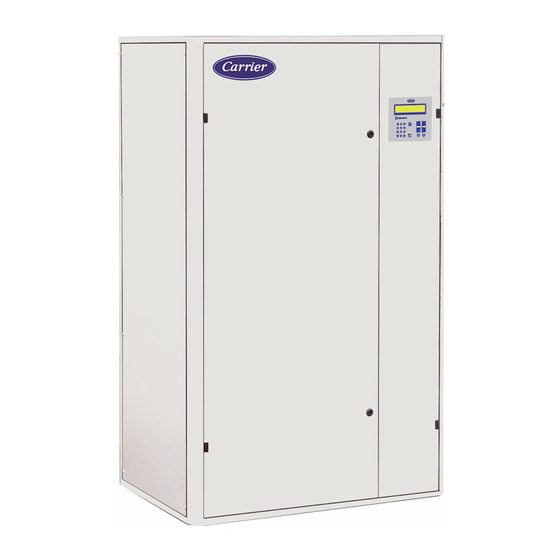
    1 - ALLGEMEINES Das Regelgerät CCU CONTROLLER gehört zur Standardausrüstung der Close Control Units. Das Einstell- und Anzeigegerät verfügt über ein LCD-Display (160 Zeichen). Das Regelgerät CCU CONTROLLER ist zudem mit einem Mikroprozessor und einer Zusatzplatine ausgestattet, die folgende Funktionen übernehmen: ■...
  • Seite 81: Aufbau

    10 - LCD-Display für bis zu 160 Zeichen Der Datenaustausch zwischen Maschine und Bediener erfolgt über einfache und präzise Meldungen am LCD-Display für bis zu 160 Zeichen. Der CCU CONTROLLER zeigt automatisch die typischen Angaben zum Betrieb der Anlage an. (BeispielAuftreten eines Fehlers).
  • Seite 82: Rückseite

    2 - AUFBAU HINWEIS: Der Text hinter der Gerätenummer zeigt den Betriebsstatus an. Die erste Zeile zeigt Datum und Uhrzeit an. Dieses Hauptmenü lässt sich von jedem beliebigen Menü aus durch Drücken der Taste „0“ aufrufen. Bewegen Sie den Cursor mit Hilfe der Pfeiltasten vor die Zeile mit den gewünschten Informationen und drücken Sie die Taste „ENTER“. Die Zeile „KONFIGURATION DER GERÄTEZAHL“...
  • Seite 83 EA = Analoge Eingänge EL = Logische Eingänge SA = Analoge Ausgänge SL = Logische Ausgänge ANSCHLUSSLEISTE CCU Controller Regeltemperaturfühler (10 KΩ). Grenztemperaturfühler in der Zuluft (10 KΩ) Fühler für zu regelnde relative Feuchte (0 - 10 V) (EA) Differenzdruckfühler am Filter (0-10 V oder 0,5 - 4,5 V)
  • Seite 84 2 - AUFBAU ANSCHLUSSLEISTE CCU Controller Steuerung des Verflüssigungssatzes 1 Gemeinsam Kühlstufe 1 (SL) Steuerung des Verflüssigungssatzes 2 Gemeinsam Kühlstufe 2 Steuerung von Stufe 1 des Elektro-Heizregisters Steuerung von Stufe 2 des Elektro-Heizregisters Gemeinsam Steuerung für Elektro-Heizregister (SL) Steuerung des Zuluftventilators...
  • Seite 85: Das Baumdiagramm

    3 - DAS BAUMDIAGRAMM Je nach Konfiguration werden nur die verwendeten Menüs angezeigt. M O N 1 0 / 0 4 / 2 0 1 7 0 9 : 3 0 h S Y S T E M C C U . C K O N F I G U R A T I O N D E R G E R Ä...
  • Seite 86 3 - BAUMDIAGRAMM Gerät 1 Ohne Fehler, Anzeige von Temperatur, Feuchte, 1 Betriebs- ENTER ENTER Sollwerten, Gerätestatus und Gerätestatus bei Master/ informationen Slave-Verbindung Wenn eine Fehlermeldung vorliegt, werden der Typ des Fehlers und die Beseitigungsmöglichkeit angezeigt (ND-Reset zur Quittierung nach der Reparatur) Zurück zum Menü...
  • Seite 87 3 - BAUMDIAGRAMM 20 Programmierschritte für 5 Programmierung der 5.1 Lüftungsbetrieb ENTER den Ventilatorbetrieb Zeitsteuerung 5.2 Sollwertverschiebung 20 Schritte zur Programmierung der Zeitschaltung, um einen Sollwert zu verschieben Zurück zum Menü 6 Schweregrad des ENTER Festlegung, ob Fehler an das Relais für leichte Fehlers Fehler oder das Relais für schwere Fehler weitergeleitet werden sollen...
  • Seite 88: Berechtigungsstufe (Menü 8)

    Zurück zum Menü Zurück zum Menü 4 - BERECHTIGUNGSSTUFE (MENÜ 8) Das Regelgerät CCU Controller verfügt über drei verschiedene Berechtigungsstufen, von denen zwei passwortgeschützt sind. Die verschiedenen Berechtigungsstufen werden über das Menü 8 aufgerufen. ■ Berechtigungsstufe 1 (kein Passwort erforderlich) Hierbei handelt es sich um die Ebene für den allgemeinen Zugriff des Endanwenders.
  • Seite 89: Konfiguration Der Gerätezahl

    5 - KONFIGURATION DER GERÄTEZAHL Diese Parameter sind nur sichtbar bei Parameter P215=1 (Mastergerät). Dieses Untermenü enthält die Betriebsparameter für die Geräte. Die Geräte können einzeln oder im Master-/Slave-Betrieb eingesetzt werden. Zugriffsebene Bezeichnung Einstellung Voreinstellung Anzeigevoraussetzung BETRIEBSKONFIGURATION 1 bis 32: unabhängig arbeitende Geräte C01 Nummer des Gerätes 2 bis 10: im Master/Slave-System arbeitende Geräte...
  • Seite 90 5 - KONFIGURATION DER GERÄTEZAHL BAUMSTRUKTUR DER KONFIGURATION DER GERÄTEZAHL (nur sichtbar bei Parameter P215 = 1 „Mastergerät“) Nummer des Gerätes Kein Notgerät Kein Zusatzgerät Ersatzgerät Zusatzgerät dient als Notgerät Zusatzgerät Ein Gerät als Zusatz- und Notgerät Ein Gerät als Notgerät Französisch Englisch Deutsch...
  • Seite 91: Konfiguration Des Gerätes

    CONTROLLER mit einem Parametersystem ausgerüstet. Es erlaubt die Konfiguration der Zusammensetzung der Anlage sowie aller Funktionen, die vom System verwaltet werden sollen. Zur Eingabe der Parameter des CCU CONTROLLER verwenden Sie das Menü Nr. 3: PARAMETER und das Untermenü Nr. 3.1: GERÄTETYP. (Menü im Display des CCU CONTROLLER) Die Parameter hängen von dem Aufbau des Gerätes ab und sollten normalerweise vor Ort nicht geändert werden.
  • Seite 92 6 - KONFIGURATION DES GERÄTES Zugriffsebene Nr. Bezeichnung Einstellung Voreinstellung Anzeigevoraussetzung WAHL DER REGELUNG 0: Keine Regelung im Heizbetrieb 1: Warmwasserregister Regelung im Heizbetrieb 2: Ein Elektro-Heizregister 3: Elektro-Heizregister oder Warmwasserregister über Kontakt 0: Keine Regelung im Entfeuchtungsbetrieb Regelung im 1: Kaltwasserregister Entfeuchtungsbetrieb 2: Direktverdampfung...
  • Seite 93 6 - KONFIGURATION DES GERÄTES Zugriffsebene Bezeichnung Einstellung Voreinstellung Anzeigevoraussetzung SPERRE 0: Konfiguration entsperrt (das Gerät kann nicht betrieben werden. die Geräteparameter können geändert werden). 1: Konfiguration gesperrt Konfigurationssperre (das Gerät kann nach betätigen des “Ein/ Aus”-Schalters am Bediengerät in Betrieb gehen.
  • Seite 94 6 - KONFIGURATION DES GERÄTES Zugriffsebene Bezeichnung Einstellung Voreinstellung Anzeigevoraussetzung FREE-COOLING-REGELUNG Differenzwert für die Free 3 bis 20 K P11 = 1 Cooling-Aktivierung Unterer Grenzwert für die Free -5 bis 20°C 0 °C P11 = 1 Cooling-Aktivierung Begrenzung der Öffnung bei Free 0 bis 100 % 100 % P11 = 1...
  • Seite 95 6 - KONFIGURATION DES GERÄTES Zugriffsebene Nr. Bezeichnung Einstellung Voreinstellung Anzeigevoraussetzung ÜBERWACHUNG DER FILTER Die Werte entsprechen der max. Luftmenge des Gerätes. Bei Drehzahländerung des Ventilators werden diese Werte proportional herabgesetzt. Sollwert für Differenzdruck zur 10 bis 80 Pa 30 Pa P02 ≠...
  • Seite 96 6.1.3 - Leseparameter (Untermenü 3.3) Dieses dritte Untermenü bietet Zugriff auf alle Werte (Temperaturen, relative Feuchten, Drücke, Zeitschaltungen, Zähler, Status der Ein- und Ausgänge usw.), die vom CCU CONTROLLER verwaltet werden. Es werden nur die verwendbaren Parameter angezeigt. Diese Werte können nicht verändert werden.
  • Seite 97 P31 = 2 oder P32 = 2 ZURÜCKZÄHLEN DER ZEITVERZÖGERUNG Standardbetriebsbedingungen Zeitschaltung für Auslösung der Verdichterstufen. P17 = 3 oder 4 VERSIONSNUMMER Software-Versionsnummer des CCU CONTROLLER TEMPERATUR FÜR DIE REGELUNG Vom Regler gemessene Temperatur °C P207 = 1 und P207 = 2 Über Modbus empfangener Temperaturwert °C...
  • Seite 98: Parameter Des Befeuchters (Werden Angezeigt, Wenn P10=2)

    6 - KONFIGURATION DES GERÄTES 6.2 - Parameter des Befeuchters (werden angezeigt, wenn P10=2) 6.2.1 - Einstellungen (Untermenü 9.1) Zugriffsebene Bezeichnung Einstellung Voreinstellung Anzeigevoraussetzung Max. Produktion 20 bis 100 % 100 % P10 = 2 Abschaltverzögerung 0 s bis 120 s P10 = 2 Wasserleitfähigkeit (0 = automatische Messung;...
  • Seite 99: Parameter Der Zuluftventilatoren (Werden Angezeigt, Wenn P05 = 1 Oder 2 Oder 3)

    6 - KONFIGURATION DES GERÄTES 6.2.3 - Alarm (Untermenü 9.3) Alarm Bezeichnung Der Befeuchter ist ohne Störung Zylinder ersetzen Zu hohe Wasserleitfähigkeit Fehler Konfigurationsparameter Fehler interner Speicher Überstrom Elektrode Geringe Dampffördermenge während reduzierter Produktion Zu hoher Wasserstand ohne Befeuchtungsanforderung Wassermangel Problem bei der Entleerung Um eine Störung am Befeuchter zu quittieren, im Menü...
  • Seite 100 6 - KONFIGURATION DES GERÄTES 6.3.2 - Informationen Ventilator 2 (Untermenü 10.2) Zugriffsebene Bezeichnung Einheit Anzeigevoraussetzung 1050 Maximale Drehzahl Ventilator 2 1/min P05 = 2 oder 3 1051 Geforderte Drehzahl für Ventilator 2 1/min P05 = 2 oder 3 1052 Aktuelle Drehzahl Ventilator 2 1/min P05 = 2 oder 3...
  • Seite 101: Schweregrad Der Fehler (Menü 6)

    7 - SCHWEREGRAD DER FEHLER (MENÜ 6) Jeder Fehlertyp kann an eines der folgenden beiden Schaltrelais weitergeleitet werden: - Relais für einfache Fehler. - Relais für schwere Fehler. In diesem Menü kann festgelegt werden, an welches Relais, einfach oder schwer, der Fehlertyp weitergeleitet wird. Bezeichnung Einstellung Einheit...
  • Seite 102: Verwendung Einer Wochenprogrammierung

    8 - WOCHENPROGRAMMIERUNG (MENÜ 5) 8.3 - Verwendung einer Wochenprogrammierung Wochenprogramm P R O G R A M M S C H A L T U H R V E N T I L A T O R S T A R T P R O G .
  • Seite 103: Messfühler

    9 - REGELUNG - Free Cooling-Betrieb W-Einheiten (Kaltwasser) • Ablufttemperaturfühler: Stufenlose Steuerung der motorbetriebenen Luftklappen und anschließend des 3-Wege-Ventils. • Zulufttemperaturfühler: Begrenzung des 3-Wege-Ventils und anschließend der Außenluftklappe. X-Einheiten (mit Direktverdampfung) • Ablufttemperaturfühler: Stufenlose Steuerung der Klappen (Verflüssigungssätze abgeschaltet). • Fühler Zulufttemperatur: Begrenzung der Außenluftklappe ■...
  • Seite 104: Inbetriebnahme

    Fehler. • Schwerer Fehler: Das betreffende Gerät steht unter Spannung. Mindestens ein schwerer Fehler ist aufgetreten. • Ausgefallen: CCU CONTROLLER des betreffenden Gerätes reagiert nicht. Entweder steht das Gerät nicht unter Spannung oder die Busverbindung ist unterbrochen. 11.2 - Betriebsdaten der einzelnen Geräte (Menü 1 „'Betriebsdaten“') •...
  • Seite 105: Alarmtabelle

    • Prüfen, ob die Luftmenge nicht zu hoch eingestellt ist Register- oder • Leck suchen und abdichten. Befeuchterleck • Messfühler überprüfen Messfühler Temperaturfühler • Anschluss und Kabel überprüfen Betriebs- oder EPROM-Speicher • Den CARRIER-Kundendienst anrufen Anzeigenausfall Batteriefehler der CPU, die Falsche Uhrzeit Zeitschaltuhr funktioniert • Batterie austauschen nicht mehr...
  • Seite 106 11 - INBETRIEBNAHME Fehler Quelle Ursache Abhilfe • Messfühler überprüfen Messfühler • Messfühler austauschen • Regelstabilität überprüfen. Zu niedrige Temperatur Temperaturfühler Funktionsstörung • Funktionstüchtigkeit des Warmwasserventils oder des Elektro- Heizregisters überprüfen. Abweichung vom • Unzureichende interne Last. Entfeuchtungswert • Messfühler überprüfen Messfühler •...
  • Seite 107: Bus Für Die Master/Slave-Funktion

    12 - BUS FÜR DIE MASTER/SLAVE-FUNKTION 12.1 - Anschluss des Busses ZWISCHEN VERSCHIEDENEN GERÄTEN CCU CONTROLLER MASTER CCU CONTROLLER SLAVE COM2 COM2 CCU CONTROLLER SLAVE Geschirmte Mehrleitungskabel ( A b s c h i r m u n g d u r c h Umflechtung) max.
  • Seite 108: Bus Für Den Anschluss An Eine Glt Rs485 Modbus

    Der Datenaustauschbus zwischen den Geräten und der GLT ist ein 2-adriger RS485-Bus Das grüne Betriebslicht zeigt an, dass Daten von der GLT an den CCU CONTROLLER übertragen werden. Das gelbe Betriebslicht zeigt an, dass Daten vom CCU CONTROLLER an die GLT übertragen werden.
  • Seite 109: Parametereinstellung Des Datenaustauschbusses (Menü 7)

    13 - BUS FÜR DEN ANSCHLUSS AN EINE GLT RS485 MODBUS 13.2 - Parametereinstellung des Datenaustauschbusses (Menü 7) Dieses Menü bietet Zugriff auf alle Parameter, die das Kommunikationsprotokoll definieren, sowie auf die Parameter für die serielle, 2-adrige RS485-Verbindung. Zugriffsebene Bezeichnung Einstellung Voreinstellung Anzeigevoraussetzung...
  • Seite 110 13 - BUS FÜR DEN ANSCHLUSS AN EINE GLT RS485 MODBUS Keine Registernr. Bezeichnung Format Einheit Min. Max. Maßstab Einstellung Reglertyp Dezimal 43 = CCU Controller 3 und 4 P258 Geregelte Temperatur Float 5 und 6 P255 Geregelte Temperatur Float °C -40,0 99,9 7 und 8...
  • Seite 111 13 - BUS FÜR DEN ANSCHLUSS AN EINE GLT RS485 MODBUS ■ Bit-Zusammensetzungen - Die Funktionen 1 und 2 werden für das Lesen verwendet. - Die Funktionen 5 und 15 werden für das Schreiben verwendet. Registernr. Bezeichnung Format Einheit 0 = Lokal P706 Steuerart Binär 1 = Extern...
  • Seite 112: Bus Für Den Anschluss An Eine Glt (Bacnet Ip Oder Mstp)

    Inbetriebnahme des CARRIER-Gerätes (1) Leistung von CARRIER, wenn eine erweiterte CARRIER-Gewährleistung (inklusive Inbetriebnahme) erworben wurde. (2) Leistung des Installateurs, wenn das Produkt ohne Inbetriebnahme durch CARRIER gekauft wurde. Hinweis: Das MODBUS-RS485-/BACNET-Gateway kann nur in Verbindung mit einem Gebäudeleittechniksystem (nicht im CARRIER-Lieferumfang enthalten) betrieben werden.
  • Seite 113: Anschluss Des Busses Zwischen Den Regelgeräten, Dem Gateway Und Der Glt

    14 - BUS FÜR DEN ANSCHLUSS AN EINE GLT (BACNET IP ODER MSTP) 14.1 - Anschluss des Busses zwischen den Regelgeräten, dem Gateway und der GLT. Modbus: Der Abstand zwischen dem Gateway und der letzten Regelung darf 1000 Meter nicht überschreiten. ■...
  • Seite 114: Informationen Für Systemintegratoren

    15 - INFORMATIONEN FÜR SYSTEMINTEGRATOREN 15.1 - Modbus Am Gateway-Satz ist eine Modbus-RTU-Kommunikation präkonfiguriert. Für die Kommunikation mit der Regelung müssen folgende Parameter im Gerät konfiguriert werden: ■ Präzisions-Klimatisierungsregelung: - P700 = Modbus - P701 = 9600 Baud (Geschwindigkeit) - P702 = ohne (Parität) - P703 = 1 (Stoppbit) - P704 = nein (nicht ausgelagert) - P705 = 1 (Busnummer)
  • Seite 115: Präzisions-Klimatisierungsregelung

    15 - INFORMATIONEN FÜR SYSTEMINTEGRATOREN 15.4 - Präzisions-Klimatisierungsregelung Verzeichnisse mit Kundenzugriff Mnemonischer BACnet- Lesen/ Bezeichnung Registernr. Format Einheit/Zahl Name Objekt Schreiben AHU Nr. 1 – AHU_1.mnemonique 3 und 4 OutdoorTemp AV0002 Float °C Außentemperatur (P258) 5 und 6 TempRegulee AV0001 Float °C Geregelte Temperatur (P255)
  • Seite 117 ÍNDICE 1 - ASPECTOS GENERALES ................................ 118 2 - COMPONENTES ..................................119 2.1 - En la parte frontal: ................................119 2.2 - En la parte posterior: ................................120 3 - ESQUEMA DE LOS MENÚS ..............................123 4 - NIVEL DE ACCESO (MENÚ 8) ..............................126 5 - CONFIGURACIÓN DEL NÚMERO DE UNIDADES ........................
  • Seite 118: Aspectos Generales

    1 - ASPECTOS GENERALES El regulador CCU CONTROLLER está incluido de serie en los sistemas Close Control Unit. Mando de ajuste y señalización con  pantalla LCD (160 caracteres). El regulador CCU CONTROLLER incorpora un microprocesador y una tarjeta adicional para garantizar  las siguientes funciones:  ■ Filtración Control de la pérdida de carga de los filtros, control del caudal de aire y del ensuciamiento.  ■ Funcionamiento (modo refrigeración) • Modelo de agua fría: Apertura progresiva de la válvula de tres vías si aumenta la temperatura.  • Modelo de expansión directa: Activación de una o de varias etapas frigoríficas si aumenta la temperatura. (Acción en la unidad exterior de condensación). ■ Funcionamiento (modo calor) - Modelo de batería de agua caliente: Apertura progresiva de la válvula de tres vías si desciende la temperatura. ...
  • Seite 119: Componentes

    DESCRIPCIÓN DE LA PARTE DELANTERA: 1 -  Puesta en marcha (led verde) 2 -  Indicador de «bajo tensión» (LED amarillo) 3 -  Indicador señal de fallo (LED rojo) 4 - Reinicio 5 -  Flechas de desplazamiento 6 -  Teclado numérico 7 -  Validación  8 -  Corrección  9 -  Valores consignas 10 - Pantalla LCD de 160 caracteres El diálogo entre las máquinas y el usuario se realiza mediante mensajes de texto simples y precisos en una pantalla LCD de 160  caracteres. El CCU CONTROLLER muestra automáticamente datos referentes al funcionamiento del grupo. (EjemploAparición de un fallo).  Se compone de:  - Una pantalla de cristal líquido retroiluminada de 4 líneas de 40 caracteres.  - Un pulsador de autorización de marcha o parada forzada, equipado con un led de señalización (led verde). • LED verde apagado → unidad parada. • LED verde parpadeante → control remoto abierto. • Led verde encendido fijo → unidad en marcha - Un indicador de presencia de tensión (led amarillo).  - Un indicador de señal de fallo (led rojo).  - Un pulsador «RESET» para rearmar los fallos.  - Un pulsador «ENTER» para validar (modificación de un valor).  - Un pulsador «C» para eliminar la última cifra visualizada en la modificación de valores.
  • Seite 120: En La Parte Posterior

    2. - COMPONENTES NOTA: el texto que sigue al número de la unidad indica su estado de funcionamiento. La primera línea es simplemente una visualización de la fecha y la hora. Accedemos a este menú principal pulsando la tecla numérica  ''0'' desde cualquier pantalla. Desplace el cursor con las flechas de desplazamiento posicionándolo frente a la línea que corresponda a la información deseada y  pulse «INTRO».  La línea «CONFIGURACIÓN DEL NÚMERO DE UNIDADES» permite configurar el funcionamiento de las unidades conectadas al  bus.  Las líneas «UNIDAD…» permiten acceder a la máquina.  Para volver al menú principal, pulse varias veces la tecla numérica ‘’0’’.  ■ Bloqueo del teclado La regulación puede bloquearse o desbloquearse pulsando simultáneamente las teclas «flecha derecha» y «flecha izquierda» durante  cinco segundos. Cuando la regulación está bloqueada, el usuario puede consultar la información, pero no modificar los ajustes. 2.2 - En la parte posterior: Los diferentes conectores permiten conectar los diferentes elementos necesarios para el control de la unidad. ■ ENTRADAS - Todo/nada: • Obtención de los estados mediante componentes electromecánicos tradicionales.  - Analógicas: • Obtención de las temperaturas mediante una sonda de tipo termistencia.  • Obtención de las humedades relativas mediante sensores que ofrecen una tensión variable entre 0 y 10 V para un rango de  0 a 100 % de humedad relativa.  • Obtención de la presión diferencial de aire en el filtro mediante un sensor que ofrece una tensión variable de 0 a 10 V o de  0,5 a 4,5 V para un rango de 0 a 1000 Pa.
  • Seite 121 2. - COMPONENTES ■ Designación de los terminales de conexión EA = entradas analógicas EL = entradas lógicas  SA = salidas analógicas SL = salidas lógicas TERMINAL DE CONEXIÓN CCU Controller Sonda de la temperatura regulable (10 kΩ) Sonda de temperatura de limitación de impulsión (10 kΩ) Sonda de humedad relativa regulable (0 - 10 V) (EA) Sonda de control de la presión diferencial en el filtro (0-10  V o 0,5 - 4,5  V) +12 V Mando a distancia  Detección de incendio/Seguridad exterior Retorno de marcha del ventilador de impulsión  Termostato de seguridad de la batería eléctrica con rearme manual (EL) Fallo o mantenimiento del humidificador Fuga de agua Común entrada lógica Resumen de fallos del grupo de condensación del circuito 1 Desfase consigna temperatura Resumen de fallos del grupo de condensación del circuito 2...
  • Seite 122 2. - COMPONENTES TERMINAL DE CONEXIÓN CCU Controller Control de la unidad exterior de condensación 1 Común etapa frigorífica n.° 1 (SL) Control de la unidad exterior de condensación 2 Común etapa frigorífica n.° 2 Control de la etapa 1 de la resistencia eléctrica Control de la etapa 2 de la resistencia eléctrica Terminal común del control de la resistencia eléctrica  (SL) Control del ventilador de impulsión  No utilizado Terminal común del control del ventilador  Alimentación 24 VCA Alimentación 24 VCA RS485 A o + (Enlace entre reguladores para función maestro/esclavo) RS485 B o - (Enlace entre reguladores para función maestro/esclavo) RS485 A o + (Enlace con gestión centralizada o pasarela) RS485 B o - (Enlace con gestión centralizada o pasarela) +12 V RS485 A o + (enlace con el humidificador CPY o GMV) RS485 B o - (enlace con el humidificador CPY o GMV) Sonda de la temperatura exterior (10K Ω) Sonda de la humedad relativa exterior (0- 10 V) Sonda de control de la presión diferencial en falso suelo (0- 10 V) (SA) Sonda de presión diferencial del ventilador (0-10 V) o sonda de temperatura regulable (2-10 V)  o porcentaje solicitado según señal externa (2-10 V) 5 V CONMUTADOR COM - COM 1: resistencia de fin de línea en conexión con la gestión técnica centralizada (véase el capítulo 13)
  • Seite 123: Esquema De Los Menús

    3 - ESQUEMA DE LOS MENÚS Dependiendo de la configuración, únicamente se visualizarán los menús utilizados. L U N 1 0 / 0 4 / 2 0 1 7 0 9 H 3 0 S I S T E M A C . C C U C O N F I G U R A C I Ó N D E L N Ú...
  • Seite 124: Estructura De Los Menús

    3. - ESTRUCTURA DE LOS MENÚS Unidad 1 Sin fallo, indicación de la temperatura, de la higrometría,  1 Información  INTRO INTRO de las consignas, del estado de la unidad y del estado de  marcha la unidad en la conexión maestro/esclavo Con fallo, indicación del tipo de fallo con solución  (pulsador reset para anular tras la reparación) Retorno menú Lista de los últimos 20 fallos con fecha y hora. Para  2 Memoria de  INTRO conocer el estado de la máquina en el momento del  fallos error, seleccionar el error con los cursores y pulsar  ENTER. Retorno menú 3.1 Tipo de 3 Parámetros INTRO equipo 3.2 Regulación y  P100 ajustes Configuración de la  máquina P249 3.3 Parámetros de P250 lectura P599...
  • Seite 125 3. - ESTRUCTURA DE LOS MENÚS 5.1 Marcha de  20 números de programación para la  5 Programación del reloj INTRO ventilación puesta en marcha del ventilador 5.2 Desfase de la  20 números de programación horaria  consigna para el desfase de la consigna Retorno menú 6 Niveles de fallo INTRO Selección para informar de los fallos en  los relés de fallos críticos y no críticos Retorno menú P700 7 Comunicación INTRO Configuración de la comunicación P706 Retorno menú 8 Nivel de acceso INTRO 8.1 Acceso nivel 1 Para modificar el nivel de  8.2 Acceso nivel 2 acceso 8.3 Acceso nivel 3 Retorno menú 9 Humidificador  INTRO 9.1 Ajustes P900 P912 Configuración del ...
  • Seite 126: Nivel De Acceso (Menú 8)

    Información sobre los  ventiladores de impulsión P1099 10.1 información  P1100 GMV3 P1149 Retorno menú Retorno menú 4 - NIVEL DE ACCESO (MENÚ 8) La regulación CCU Controller cuenta con tres niveles de acceso y para dos de ellos se necesita un código. El acceso a los diferentes  niveles se realiza desde el menú 8, en el menú de la unidad.  ■ Acceso al nivel 1 (sin código de acceso) Se trata del nivel general destinado al usuario final. Este nivel permite acceder a todos los parámetros de lectura y al ajuste de las  principales consignas y bandas proporcionales:  - Refrigeración  - Calefacción  - Humidificación  - Deshumidificación  - Limitaciones de temperatura en la impulsión  - Umbrales límite de temperatura y de higrometría ...
  • Seite 127: Configuración Del Número De Unidades

    5 - CONFIGURACIÓN DEL NÚMERO DE UNIDADES Estos parámetros únicamente son visibles si el parámetro P215 = 1 (unidad maestra) Este submenú agrupa los parámetros de funcionamiento de las unidades. Pueden funcionar individualmente o agrupadas en maestra/ esclavas. Nivel de N.° Descripción Ajuste Predeterminado Condición de visualización acceso CONFIGURACIÓN DE FUNCIONAMIENTO 1 a 32: en unidades independientes C01 Número de unidad 2 a 10: en maestro/esclavo 0: Sin unidad complementaria...
  • Seite 128 5 - CONFIGURACIÓN DEL NÚMERO DE UNIDADES ESQUEMA DE LA CONFIGURACIÓN DEL NÚMERO DE UNIDADES (únicamente son visibles con el parámetro P215 = 1 «unidad maestra») Número de unidad Sin apoyo Sin complementaria Apoyo La unidad complementaria se usa como  Complementaria apoyo Una unidad complementaria de apoyo  Una unidad de apoyo Francés Inglés Alemán Sin rotación Español Rotación automática Temporización de rotación Desbloqueada Reactivación periódica Bloqueada Número de días entre 2  reactivaciones Hora de reactivación Duración de la reactivación Desfase de la consigna de frío Consigna de activación ...
  • Seite 129: Configuración De La Unidad

    Para configurar el CCU CONTROLLER, utilice el menú n.° 3: PARÁMETRO y el submenú n.° 3.1: TIPO DE EQUIPO. (menú de la  pantalla del CCU CONTROLLER)  Estos parámetros están directamente relacionados con la composición de la unidad y, en principio, no deben modificarse in situ. La memorización de estos parámetros se realiza en fábrica. (Para visualizar el tipo de programación específica de su pedido, consulte  el manual de configuración que se adjunta con el equipo).  Para modificar los parámetros P01 a P99, la unidad debe estar parada y la configuración desbloqueada. El parámetro P99 (bloqueo  de la configuración) está equipado con un sistema que recoge el número de desbloqueos de la configuración.  La  mayoría  de  parámetros  solo  pueden  modificarse  si  se  accede  al  nivel  de  habilitación  adecuado  en  el  menú  n.°  8  del  CCU CONTROLLER (ver el capítulo 4 del presente manual). Nivel de Condición de N.° Descripción Ajuste...
  • Seite 130 6 - CONFIGURACIÓN DE LA UNIDAD Nivel de Condición de N.° Descripción Ajuste Predeterminado acceso visualización ELECCIÓN DE LA REGULACIÓN 0: Sin regulación en calefacción 1: Una batería de calefacción de agua Regulación en calefacción 2: Una batería de calefacción eléctrica 3: Batería eléctrica o batería de agua caliente por  contacto 0: Sin regulación en deshumidificación Regulación en  1: Una batería de agua fría deshumidificación 2: Un sistema de expansión directa 0: Sin regulación en humidificación Control de la humidificación 2: Progresivo MODBUS 0 = sin  Regulación en free-cooling P07 > 0 1 = con CONFIGURACIÓN DE LOS INTERCAMBIADORES 1: Una salida todo o nada (una etapa) Control de la resistencia ...
  • Seite 131 6 - CONFIGURACIÓN DE LA UNIDAD Nivel de acceso N.° Descripción Ajuste Predeterminado Condición de visualización BLOQUEO 0: Configuración desbloqueada  (La unidad no puede arrancar, se pueden  modificar los parámetros de tipo de equipo). 1: Configuración bloqueada  Bloqueo de la  (La  unidad  puede  arrancar  después  de  configuración presionar el pulsador "Arranque/Paro" del  mando.  No  se  pueden  modificar  los  parámetros de tipo de equipo. Se contabiliza  el número de desbloqueos.) (*) Con la modificación de estos parámetros, se inicia una secuencia para la configuración de los grupos motoventiladores.
  • Seite 132 6 - CONFIGURACIÓN DE LA UNIDAD Nivel de N.° Descripción Ajuste Predeterminado Condición de visualización acceso REGULACIÓN EN FREE-COOLING Diferencial activación del  3 a 20 K 3 K P11 = 1 free-cooling Consigna límite inferior  -5 a 20 °C 0 °C P11 = 1 activación del free-cooling Límite de apertura free cooling 0 a 100 % 100 % P11 = 1 P11 = 1 y  Consigna límite inferior en peso  0 a 15 g 4 g (P09>0 o ...
  • Seite 133 6 - CONFIGURACIÓN DE LA UNIDAD Nivel de N.° Descripción Ajuste Predeterminado Condición de visualización acceso CONTROL DE LOS FILTROS Los valores corresponden al caudal de aire máximo del equipo. En caso de variación de la velocidad del ventilador, estos valores se reducen de forma proporcional. Consigna de la presión diferencial  de indicación de la presencia de  10 a 80 Pa 30 Pa P02 ≠ 17 caudal de aire Consigna de la presión diferencial  de indicación de ensuciamiento  60 a 500 Pa 150 Pa del filtro Consigna de la presión diferencial  100 a 550 Pa 190 Pa de indicación del filtro obstruido CONTROL DEL CAUDAL DE AIRE Límite inferior del caudal de aire...
  • Seite 134 2-10 V Consigna de temperatura de calor  MÁX. (8,P212) a 45,0 °C si P07>0 20,0 °C P08 > 0 y P207 = 2 en fallo de la sonda 2-10 V BUS MAESTRO/ESCLAVO Número de unidad en el mando 1 a 32 6.1.3 - Parámetros de lectura (submenú 3.3) Desde este tercer submenú se accede a todos los valores gestionados por CCU CONTROLLER (temperaturas, humedades relativas,  presiones, temporizaciones, contadores, estados de las entradas y salidas, etc.). Solo se visualizan los parámetros útiles. No pueden  modificarse.  Los contadores se pueden poner a cero. Para ello, sitúe el cursor sobre el contador elegido y pulse simultáneamente las teclas Reset  y 0 durante 5 a 6 segundos.  A todos estos parámetros se puede acceder desde el nivel de acceso «Cliente».  Nivel de acceso N.° Descripción Unidad Condición de visualización...
  • Seite 135 ESTADO DE LOS CONTROLES DEL VENTILADOR Demande de marche de ventilateur  Off/on P01 = 2 Solicitud de desfase de la consigna de temperatura  Off/On P31 = 2 o P32 = 2 CUENTA ATRÁS DE TEMPORIZACIÓN Puesta en funcionamiento Temporización de la activación de las etapas de los compresores P17 = 3 o 4 NÚMERO DE VERSIÓN Número de versión del software del CCU CONTROLLER TEMPERATURA PARA REGULACIÓN Temperatura medida por el regulador °C P207 = 1 y P207=2 Temperatura recibida por Modbus °C P207 = 1 Temperatura medida en la entrada 2-10 V °C (P07>0 o P08>0) y P207=2 porcentaje según señal externa (P07 > 0 y P08 = 0) y (P207 = 3)
  • Seite 136: Parámetros Del Humidificador (Visible Si P10 = 2)

    6 - CONFIGURACIÓN DE LA UNIDAD 6.2 - Parámetros del humidificador (visible si P10 = 2) 6.2.1 - Ajustes (submenú 9.1) Nivel de acceso N.° Descripción Ajuste Predeterminado Condición de visualización Producción máxima 20 a 100 % 100 % P10 = 2 Tiempo de retardo en parada 0 s a 120 s P10 = 2 Conductividad del agua...
  • Seite 137: Parámetros De Los Ventiladores De Impulsión (Visible Si P05 = 1 O 2 O 3)

    6 - CONFIGURACIÓN DE LA UNIDAD 6.2.3 - Alarma (submenú 9.3) Alarma Descripción El humidificador no tiene errores Sustituir el cilindro Conductividad del agua demasiado elevada Error de parámetro de configuración Error de memoria interna Sobreintensidad electrodo  Bajo caudal de vapor durante producción reducida Nivel de agua elevado sin demanda de humidificación Falta de agua alimentación Problema de vaciado  Para confirmar un fallo del humidificador hay que estar en el menú «ALARMA» (menú 9.3) y pulsar la tecla «Reset» 6.3 - Parámetros de los ventiladores de impulsión (visible si P05 = 1 o 2 o 3) 6.3.1 - Información del GMV1 (submenú...
  • Seite 138 6 - CONFIGURACIÓN DE LA UNIDAD 6.3.2 - Información del GMV2 (submenú 10.2.) Nivel de acceso N.° Descripción Unidad Condición de visualización 1050 Velocidad máx. del GMV2 P05 = 2 o 3 1051 Velocidad demandada al GMV2  P05 = 2 o 3 1052 Velocidad actual del GMV2 P05 = 2 o 3 1053 Intensidad consumida por el GMV2 P05 = 2 o 3  1054 Tensión de alimentación pico del GMV2 P05 = 2 o 3  1055 Potencia absorbida por el GMV2 P05 = 2 o 3 1060 Resumen de fallos del GMV2 Off/On...
  • Seite 139: Nivel De Los Errores (Menú 6)

    7 - NIVEL DE LOS ERRORES (MENÚ 6) Cada tipo de errores puede reflejarse en uno de los dos relés de contactos inversores siguientes: - Relé de fallo no crítico. - Relé de fallo crítico. Este menú permite configurar hacia qué relé, no crítico o crítico, se remitirá el fallo. N.° Descripción Ajuste Unidad Condición de visualización 0: Fallo no crítico N02 Ausencia de caudal de aire (*) 1: Fallo crítico 0: Fallo no crítico N03 Ventilador (*) 1: Fallo crítico  (Unidad de condensación  0: Fallo no crítico Baja presión de cada circuito P17 > 0 1: Fallo crítico Alta presión o disyunción de cada circuito) 0: Fallo no crítico N05 Filtración sucia 1: Fallo crítico ...
  • Seite 140: Uso De Una Programación Semanal

    8 - PROGRAMACIÓN SEMANAL (MENÚ 5) 8.3 - Uso de una programación semanal Programa semanal P R O G . R E L O J F U N C I O N A M I E N T O V E N T I L A C I Ó N P R O G .
  • Seite 141: Sondas

    9 - REGULACIÓN - Funcionamiento en modo free cooling Unidades W (agua fría) • Sonda de temperatura de aire de retorno: control progresivo de las compuertas motorizadas y, a continuación, de la válvula de  tres vías. • Sonda de temperatura de impulsión: limitación de la válvula de tres vías y, a continuación, de la compuerta de AIRE NUEVO. Unidades X (expansión directa) • Sonda de temperatura del aire de retorno: control progresivo de las compuertas (unidades de condensación paradas). • Sonda de temperatura de impulsión: limitación de compuerta AIRE NUEVO ■ Regulación de la humedad relativa considerada «regulable» Es de tipo proporcional o proporcional integral.  - Regulación en deshumidificación La regulación maestra se incrementa si la humedad relativa supera el valor de consigna. Este valor disminuye según la configuración  (parámetro de tipo de equipo) y lo hace en el siguiente orden:  • Por etapas para el control de la unidad de condensación. • Progresiva para el control de la válvula de agua fría.  • Por etapas para indicar el exceso de humedad relativa.  Según la configuración de la unidad en proporcional puro, puede mantenerse una diferencia entre la consigna y la propia medición con todos ...
  • Seite 142: Puesta En Marcha

    • En fallo no crítico: la unidad en cuestión está conectada a la corriente. Tiene al menos un fallo no crítico, pero ningún fallo  crítico. • En fallo crítico: la unidad en cuestión está conectada a la corriente. Tiene al menos un fallo crítico. • En desconexión: el CCU CONTROLLER de la unidad en cuestión no responde. No está conectada a la corriente o el enlace  bus está cortado. 11.2 - Información de funcionamiento de cada unidad (menú 1 «Info marcha») • Unidad sin fallo La primera línea muestra los valores medidos por las sondas de temperatura y/o de humedad relativa regulables. La segunda línea muestra los valores de consigna de temperatura y/o de humedad relativa regulables.  Para  ambos  valores,  el  valor  visualizado  es  la  consigna  del  último  modo  de  regulación  (calor  o  frío,  humidificación  o ...
  • Seite 143: Tabla De Alarmas

    • Añada una pizca de sal en el cilindro • Consulte las indicaciones de la placa de mando del humidificador Desbordamiento de la  • Compruebe el funcionamiento correcto de la válvula de vaciado  Vaciado  bandeja • Compruebe que el circuito de vaciado no esté obstruido Parada de la producción de  •    Consultar el manual o el autómata del grupo para diagnosticar la  Grupo de condensación frío avería. • Compruebe el diseño correcto del sifón Desbordamiento de la  • Compruebe el cebado del sifón bandeja • Compruebe que los condensados fluyan correctamente  Sonda de fuga de  Fuga de agua  • Compruebe que el caudal de aire no sea demasiado elevado agua Fuga en batería o  • Busque la fuga y tapónela humidificador Sonda de  • Compruebe la sonda  Sonda  temperatura • Compruebe la conexión y la continuidad del cable Deja de funcionar o no  Eprom memoria • Póngase en contacto con el servicio de posventa de CARRIER aparece nada en pantalla  Fallo de pila de la tarjeta  La hora es incorrecta • Cambie la pila  CPU, el reloj no funciona...
  • Seite 144 11 - PUESTA EN MARCHA Problema Fuentes Causas Soluciones • Compruebe la sonda. Sonda • Cambie la sonda. • Compruebe la estabilidad de la regulación. Sonda de  Temperatura baja Mal funcionamiento • Compruebe el funcionamiento de la válvula de calor o de la  temperatura batería eléctrica. Deshumidificación • Carga interna insuficiente. • Compruebe la sonda. Sonda • Cambie la sonda.  • Compruebe la estabilidad de la regulación. Sonda de  Temperatura alta Mal funcionamiento •    Compruebe el funcionamiento de la válvula de frío y de los  temperatura compresores. Sobrecarga de Tª del local • Revise las cargas del local. • Compruebe la sonda.  Sonda  • Cambie la sonda.  Higrometría baja Sonda de humedad • Compruebe la estabilidad de la regulación.
  • Seite 145: Bus Para Función Maestro/Esclavo

    J9  Unidad 1 Unidad 2 Unidad 3 Regulador Regulador Regulador CCU CONTROLLER CCU CONTROLLER CCU CONTROLLER (P215 = 1) (P215 = 2) (P215 = 3) En  la  regulación  de  la  unidad  1,  en  el  menú  "CONFIGURACIÓN DEL NÚMERO DE UNIDADES",  "CONFIGURACIÓN DE FUNCIONAMIENTO", ajuste el parámetro "C01 NÚMERO DE UNIDADES": (3 en el ejemplo). ...
  • Seite 146: Bus Para Conexión A Una Gestión Centralizada Rs485 Modbus

    CONTROLLER: 1000 m 1: Línea A o + 2: Línea B o - 3: Tierra Para  un  funcionamiento  correcto,  la  línea debe estar polarizada. Unidad(es) intermedia(s) Cables  multiconductores  blindados  con  recubrimiento  (blindaje  por  COM1 trenzado), longitud entre el primer y el  último CCU CONTROLLER: 1000 m 1: Línea A o + 2: Línea B o - 3: Tierra Última unidad COM1 COM1: conmutador de resistencia de fin de línea - Primera unidad = OFF - Unidad intermedia = OFF - Última unidad = ON...
  • Seite 147: Configuración De Los Parámetros Del Bus De Comunicación (Menú 7)

    13 - BUS PARA CONEXIÓN A UNA GESTIÓN CENTRALIZADA RS485 MODBUS 13.2 - Configuración de los parámetros del bus de comunicación (menú 7) Desde este menú se accede a todos los parámetros que permiten definir el protocolo de comunicación y a los parámetros del enlace  en serie RS485 de dos cables. Condición de Nivel de acceso N.° Descripción Ajuste Predeterminado visualización Modo de comunicación 1: MODBUS/JBUS 0: 4800 baudios Velocidad de comunicación 1: 9600 baudios 2: 19 200 baudios 0: Sin Paridad...
  • Seite 148 13 - BUS PARA CONEXIÓN A UNA GESTIÓN CENTRALIZADA RS485 MODBUS Ausencia N.° registro Descripción Formato Tipo Unidad Mín. Máx. Escala de ajuste Tipo de regulador Decimal 43 = CCU Controller 3 y 4 P258 temperatura ajustada Float 5 y 6 P255 temperatura ajustada Float °C -40,0 99,9 7 y 8 P256 higrometría ajustada Float % Hr 9 y 10...
  • Seite 149 13 - BUS PARA CONEXIÓN A UNA GESTIÓN CENTRALIZADA RS485 MODBUS ■ Composiciones de los bits - Utilización de las funciones 1 o 2 para lectura - Utilización de las funciones 5 o 15 para escritura N.° registro Descripción Formato Tipo Unidad 0 = local P706 tipo de control  Binario 1 = a distancia 0 = parada P330 funcionamiento del ventilador de impulsión Binario  R  1 = marcha 0 = parada P300 funcionamiento del compresor 1 Binario  1 = marcha 0 = parada P304 funcionamiento del compresor 2  Binario  1 = marcha 0 = parada P320 funcionamiento de la batería eléctrica etapa 1 Binario ...
  • Seite 150: Bus Para Conexión A Una Gestión Centralizada (Bacnet Ip Omstp)

    Comprobación de conexión del kit de pasarela en lado RS 485 - BACNET Puesta en marcha del equipo CARRIER (1) Prestación CARRIER incluida con la contratación de la extensión de garantía CARRIER (incluye la puesta en marcha) (2) Prestación del instalador si no se ha contratado la puesta en marcha a CARRIER Nota: La pasarela MODBUS RS485 / BACNET solo puede funcionar correctamente si está conectada a un sistema de gestión técnica de edificios (no suministrado por CARRIER).
  • Seite 151: Conexión Del Bus Entre Los Reguladores, La Pasarela Y La Gestión Técnica Centralizada

    14 - BUS PARA CONEXIÓN A UNA GESTIÓN CENTRALIZADA (BACNET IP O MSTP) 14.1 - Conexión del bus entre los reguladores, la pasarela y la gestión técnica centralizada Modbus: La distancia entre la pasarela y el último regulador debe ser inferior a 1000 metros.  ■ Un armario como máximo puede dialogar con la pasarela BACnet.  ■ El cable de comunicación que se debe utilizar debe ser de tipo: ARMARIO N.° 1 AWG24 - 22 (1 par trenzado blindado) ■ A  noter  qu’au-delà  d’une  certaine  distance  et  en  fonction  du ...
  • Seite 152: Información Para El Integrador

    15 - INFORMACIÓN PARA EL INTEGRADOR 15.1 - Modbus La comunicación Modbus RTU está preconfigurada en el kit pasarela. Para garantizar la comunicación con la regulación, es preciso  configurar los parámetros siguientes en el equipo: ■ Reguladores de climatización de precisión: - P700 = Modbus - P701 = 9600 baudios (velocidad) - P702 = sin (paridad) - P703 = 1 (bit de stop) - P704 = no (no intercambiado) - P705 = 1 (n.° de bus) - P706 = remoto ■ Nota: - Versiones compatibles con la pasarela: • Climatización de precisión: a partir de la versión V21 En el caso de una versión anterior, el servicio deberá actualizar la regulación de la máquina, de lo contrario, pueden aparecer errores  de comunicación. 15.2 - BACnet IP La instalación de la comunicación BACnet debe ser realizada por un integrador BACnet. ■...
  • Seite 153: Regulador De Climatización De Precisión

    15 - INFORMACIÓN PARA EL INTEGRADOR 15.4 - Regulador de climatización de precisión Registros accesibles cliente Objeto Lectura/ Unidad/ Descripción N.° registro Nemotécnica Formato BACnet escritura enumeración AHU n°1 – AHU_1.mnemonique 3 y 4 OutdoorTemp AV0002 Float °C Temperatura exterior (P258) 5 y 6 TempRegulee AV0001...
  • Seite 155 INHOUDSOPGAVE 1 - ALGEMEEN ....................................156 2 - ONDERDELEN ..................................157 2.1 - Op de voorzijde: ................................... 157 2.2 - Aan de achterzijde: ................................158 3 - MENUSTRUCTUUR .................................. 161 4 - TOEGANGSNIVEAU (MENU 8) ..............................164 5 - CONFIGUREREN AANTAL EENHEDEN ..........................165 6 - CONFIGUREREN VAN DE EENHEID ............................
  • Seite 156: Algemeen

    1 - ALGEMEEN De CCU CONTROLLER is standaard aanwezig op Close Control Unit-systemen. Instel- en weergavepaneel voorzien van een 160-karakter LCD-scherm. De CCU CONTROLLER is voorzien van een microprocessor en een additionele kaart om in de volgende functies te voorzien: ■...
  • Seite 157: Onderdelen

    10 - 160-karakter LCD-scherm De dialoog tussen de machines en de gebruiker verloopt via eenvoudige, beknopte tekstmeldingen op een 160-karakter LCD-scherm. De CCU CONTROLLER toont automatisch informatie over het bedrijf van de eenheid. (voorbeeldverschijnen van een storing). Het bestaat uit: - Een verlicht LC-display met 4 regels van 40 karakters.
  • Seite 158: Aan De Achterzijde

    2 - SAMENSTELLING OPMERKING: de tekst na het eenheidnummer geeft de bedrijfsstatus aan. De eerste regel is eenvoudigweg een weergave van de datum en tijd. U kunt toegang tot dit hoofdmenu krijgen via de "0"-toets vanuit elk display. Beweeg de cursor naar de regel met de gewenste informatie met behulp van het cursorveld en druk op "ENTER". De regel "CONFIGURATION OF NUMBER OF UNITS"’...
  • Seite 159 2 - SAMENSTELLING ■ Identificatie van klemmen EA = analoge ingangen EL = logische ingangen SA = analoge uitgangen SL = logische uitgangen KLEM CCU Controller Sensor gewenste temperatuur (10 K Ω) Grenswaardetemperatuursensor toevoerlucht (10 K Ω) Sensor gewenste relatieve vochtigheid (0 - 10 V) (EA) Sensor voor regeling van het drukverschil op het filter (0-10 V of 0,5 - 4,5 V) +12 V...
  • Seite 160 2 - SAMENSTELLING KLEM CCU Controller Condensing-unit 1 regeling Koeltrapnr. 1 gemeenschappelijk klem (SL) Condensing-unit 2 regeling Koeltrapnr. 2 gemeenschappelijk klem Regeling van elektrisch verwarmingselement trap 1 Regeling van elektrisch verwarmingselement trap 2 Regeling elektrisch verwarmingselement gemeenschappelijke klem (SL) Commando uitblaasventilator...
  • Seite 161: Menustructuur

    3 - MENUSTRUCTUUR Afhankelijk van de configuratie worden alleen de gebruikte menu's getoond. M N D 1 0 / 4 / 2 0 1 7 0 9 : 3 0 C C U S Y S T E E M C O N F I G U R A T I E A A N T A L E E N H E D E N E E N H E I D...
  • Seite 162 3 - MENUSTRUCTUUR Eenheid 1 Indien geen storing aanwezig is, worden de temperatuur, vochtigheid, setpoints en status van de eenheid op de ENTER ENTER 1 Bedrijfsinformatie master/slave-verbinding getoond Bij aanwezigheid van een storing wordt het type van de storing getoond samen met oplossingsmaatregelen (resetknop voor bevestigen na het oplossen) Terug naar menu...
  • Seite 163 3 - MENUSTRUCTUUR 20 programmeerstappen voor 5.1 Ventilatie aan 5 Timerprogrammering ENTER inschakelen van de ventilator 20 timer programmeerstappen 5.2 Setpoint-offset voor verschuiven setpoint Terug naar menu 6 Storingsniveau ENTER Keuze voor doorgeven storingen aan de kritische of niet-kritische storingsrelais Terug naar menu P700...
  • Seite 164: Toegangsniveau (Menu 8)

    Terug naar menu 4 - TOEGANGSNIVEAU (MENU 8) De CCU CONTROLLER heeft 3 toegangsniveaus, voor twee daarvan is een toegangscode nodig. De verschillende niveaus zijn toegankelijk via het menu 8 in de eenheid. ■ Toegang tot niveau 1 (geen toegangscode) Dit is een algemeen niveau bedoeld voor de eindgebruiker.
  • Seite 165: Configureren Aantal Eenheden

    5 - CONFIGUREREN AANTAL EENHEDEN Deze parameters zijn alleen zichtbaar indien parameter P215 = 1 (master eenheid) Dit submenu groepeert de bedrijfsparameters voor de eenheden. Deze kunnen individueel worden bediend of gegroepeerd als master/ slaves. Toegangsniveau Omschrijving Instelling Standaard Weergaveconditie CONFIGURATIE 1 tot 32: onafhankelijk werkende eenheden C01 Aantal eenheden...
  • Seite 166 5 - CONFIGUREREN AANTAL EENHEDEN MENUSTRUCTUUR VOOR CONFIGUREREN AANTAL EENHEDEN (alleen zichtbaar als parameter P215 = 1 "master eenheid") Aantal eenheden Geen back-up Geen extra Backup De extra eenheid werkt als backup Extra Een extra backup eenheid Een backup eenheid Nederlands Nederlands Duits...
  • Seite 167: Configureren Van De Eenheid

    Parameter  P99  (vergrendeling  van  configuratie)  is  uitgerust  met  een  systeem  die  het  aantal  keren  telt  dat  de  configuratie  wordt  vrijgegeven. De meeste parameters kunnen alleen worden gewijzigd, wanneer het correcte autorisatieniveau is ingesteld in menu nr. 8 van de CCU CONTROLLER (zie hoofdstuk 4 in deze handleiding).
  • Seite 168 6 - CONFIGUREREN VAN DE EENHEID 0: geen verwarmingsregeling 1: een warmwaterbatterij Regeling verwarming 2: een elektrisch verwarmingselement 3: elektrisch verwarmingselement of warmwaterbatterij via contact Toegangsniveau Omschrijving Instelling Standaard Weergaveconditie SELECTIE REGELING 0: geen verwarmingsregeling 1: een warmwaterbatterij Regeling verwarming 2: een elektrisch verwarmingselement 3: elektrisch verwarmingselement of warmwaterbatterij via contact...
  • Seite 169 6 - CONFIGUREREN VAN DE EENHEID Toegangsniveau Omschrijving Instelling Standaard Weergaveconditie CONFIGURATIE 0: configuratie ontgrendeld  (de eenheid kan niet worden opgestart; de parameters voor de eenheid kunnen worden gewijzigd). 1: configuratie vergrendeld  Vergrendeling van de (de eenheid kan worden gestart door configuratie indrukken van de "aan/uit"-drukknop op het paneel.
  • Seite 170 6 - CONFIGUREREN VAN DE EENHEID Toegangsniveau Omschrijving Instelling Standaard Weergaveconditie REGELING VRIJE KOELING Activeren vrije koeling 3 tot 20 K P11 = 1 differentiaal Activeren vrije koeling -5 tot 20°C 0 °C P11 = 1 ondergrens setpoint Vrije koeling openen grenswaarde 0 tot 100% 100% P11 = 1 P11 = 1 en...
  • Seite 171 6 - CONFIGUREREN VAN DE EENHEID Toegangsniveau Omschrijving Instelling Standaard Weergaveconditie CONTROLEER DE FILTERS De waarden komen overeen met het maximale luchtdebiet van de eenheid. Wanneer er een variatie aanwezig is in het ventilatortoerental, worden deze proportioneel gereduceerd Setpoint voor drukverschil dat aangeeft of 10 tot 80 Pa 30 Pa P02 ≠ 17...
  • Seite 172 6.1.3 - Uitleesparameters (submenu 3.3) Dit derde submenu geeft toegang tot alle waarden (temperatuur, relatieve vochtigheid, drukken, vertragingen, meetwaarden, ingangs- en uitgangsstatussen, enz.) beheerd door de CCU CONTROLLER.. Alleen de nuttige parameters worden weergegeven. Deze kunnen niet worden gewijzigd De metingen kunnen naar nul worden gereset. Plaats hiervoor de cursor op de betreffende meetwaarde en druk tegelijkertijd gedurende 5 tot 6 seconden op de reset- en de 0-toets.
  • Seite 173 P31 = 2 of P32 = 2 AFTELLEN VERTRAGING Opwarmen Activeren vertraging voor de compressortrappen P17 = 3 of 4 VERSIENUMMER CCU CONTROLLER softwareversienummer TEMPERATUUR VOOR REGELING Temperatuur gemeten door de controller °C P207 = 1 en P207=2 Temperatuur ontvangen door ModBus °C...
  • Seite 174: Parameters Bevochtiger (Zichtbaar Als P10 =2)

    6 - CONFIGUREREN VAN DE EENHEID 6.2 - Parameters bevochtiger (zichtbaar als P10 =2) 6.2.1 - Instellingen (submenu 9.1) Toegangsniveau Omschrijving Instelling Standaard Weergaveconditie Maximale productie 20 tot 100% 100% P10 = 2 Uit-vertraging 0 s tot 120 s P10 = 2 Watergeleidbaarheid (0 = automatische meting >...
  • Seite 175: Parameters Toevoeluchtventilator (Zichtbaar Als P05 = 1 Of 2 Of 3)

    6 - CONFIGUREREN VAN DE EENHEID 6.2.3 - Alarm (submenu 9.3) Alarm Omschrijving De bevochtiger is niet in storing Vervang de cilinder Watergeleidbaarheid te hoog Fout configuratie parameter Fout intern geheugen Te hoge stroom elektrode Laag stoomdebiet tijdens gereduceerde productie Waterniveau verhoogd zonder bevochtigingsvraag Tekort aan voedingswater Aftapprobleem Ga, om een fout op de bevochtiger te bevestigen, naar het "ALARM"-menu (menu 9.3) en druk op de "Reset"-toets...
  • Seite 176 6 - CONFIGUREREN VAN DE EENHEID 6.3.2 - FMA2 informatie (submenu 10.2) Toegangsniveau Omschrijving Eenheid Weergaveconditie 1050 FMA2 max. toerental P05 = 2 of 3 1051 FMA2 gevraagd toerental P05 = 2 of 3 1052 FMA2 actueel toerental P05 = 2 of 3 1053 FMA2 opgenomen stroom P05 = 2 of 3...
  • Seite 177: Storingsniveau (Menu 6)

    7 - STORINGSNIVEAU (MENU 6) Elk type storing kan worden doorgestuurd naar een van de volgende twee omschakelrelais: - Relais niet-kritische storingen. - Relais kritische storingen. Dit menu wordt gebruik om in te stellen welk type storing naar welk relais wordt doorgestuurd (kritisch of niet-kritisch). Omschrijving Instelling Eenheid Weergaveconditie...
  • Seite 178: Gebruik Van Het Weekprogramma

    8 - WEEKPROGRAMMERING (MENU 5) 8.3 - Gebruik van het weekprogramma Weekprogramma V E N T I L A T I E T I M E R P R O G R A M M A P R O G . : A C T I V E E R D E A C T I V E E R B E V E S T I G...
  • Seite 179: Sensoren

    9 - REGELING • Getrapt voor indicatie dat de ondergrenswaarde voor de temperatuur is overschreden. Afhankelijk van de strikt proportionele samenstelling van de eenheid, kan een verschil blijven bestaan tussen het setpoint en de meetwaarde, zelfs met alle elementen ingesteld op 0. - Bedrijf in vrije koelingsmodus W (gekoeld water) eenheden •...
  • Seite 180: Inbedrijfstelling

    • Met kritische storing: de betreffende eenheid wordt opgestart. Het heeft tenminste één kritische storing. • Uitgeschakeld: de CCU CONTROLLER voor de betreffende eenheid reageert niet. Het is niet opgestart of de verbinding is verbroken. 11.2 - Bedrijfsinformatie voor elke eenheid (menu 1 "bedieningsinfo'') •...
  • Seite 181: Tabel Van De Alarmen

    • Controleer de sensor Sensor Temperatuursensor • Controleer de verbinding van de kabel Display buiten bedrijf EPROM-geheugen • Neem contact op met CARRIER After-Sales Storing van de CPU De tijd is fout kaartbatterij - de timer werkt • Vervang de batterij niet meer...
  • Seite 182 11 - INBEDRIJFSTELLING Storingen Bronnen Oorzaken Oplossingen • Controleer de sensor Sensor • Vervang de opnemer • Controleer de stabiliteit van de regeling Lage temperatuur Temperatuursensor Storing • Controleer de werking van de verwarmingsklep of het elektrisch verwarmingselement Drift in ontvochtigingsmodus • Interne belasting onvoldoende •...
  • Seite 183: Bus Voor Master/Slave-Functie

    , m e t m a n t e l (afscherming met vlechtwerk), lengte tussen eerste en laatste CCU CONTROLLER: 1000 m 1: ader A of + 2: ader B of -...
  • Seite 184: Bus Voor Aansluiting Op Een Rs485 Modbus Gbs

    De communicatiebus tussen de eenheid en de GBS is een 2-draads RX485-bus Het groene lampje geeft aan dat de gegevens die door de GBS zijn verzonden aan de CCU CONTROLLER zijn ontvangen. Het gele lampje geeft aan dat gegevens door de CCU CONTROLLER zijn verzonden aan de GBS.
  • Seite 185: Configureren Van De Communicatie-Busparameters (Menu 7)

    13 - BUS VOOR AANSLUITING OP EEN RS485 MODBUS GBS 13.2 - Configureren van de communicatie-busparameters (menu 7) Dit menu geeft toegang tot alle parameters die worden gebruikt voor het definiëren van het communicatieprotocol en de parameters  voor de 2-draads RS485 seriële verbinding. Toegangsniveau Omschrijving Instelling Standaard Weergaveconditie Communicatiemode 1: MODBUS/JBUS 0: 4800 baud Communicatiesnelheid 1: 9600 baud 2: 19200 baud 0: geen Pariteit...
  • Seite 186 13 - BUS VOOR AANSLUITING OP EEN RS485 MODBUS GBS Registernr. Omschrijving Formaat Type Eenheid Instelstap Schaal Type regelaar Decimaal 43 = CCU Controller 3 en 4 P258 geregelde temperatuur Zwevend 5 en 6 P255 geregelde temperatuur Zwevend °C -40,0...
  • Seite 187 13 - BUS VOOR AANSLUITING OP EEN RS485 MODBUS GBS ■ Bitsamenstelling - Functie 1 of 2 wordt gebruikt voor lezen - functie 5 of 15 wordt gebruikt voor schrijven Registernr. Omschrijving Formaat Type Eenheid 0 = Lokaal P706 Type commando Binair 1 = Bediening op afstand...
  • Seite 188: Bus Voor Aansluiting Op Een Gbs Bacnet Ip Of Mstp

    14 - BUS VOOR AANSLUITING OP EEN GBS BACNET IP OF MSTP Als optie geïntegreerd in de verticale eenheid, levert CARRIER een MODBUS RTU --> BACNET IP of MODBUS RTU --> BACNET MSTP-gateway. De gateway wordt gebruikt voor het vertalen van de hoofdinformatie uit MODBUS naar BACNET.
  • Seite 189: Busverbinding Tussen De Controllers, De Gateway En De Cms

    14 - BUS VOOR AANSLUITING OP EEN CMS BACNET IP OF MSTP 14.1 - Busverbinding tussen de controllers, de gateway en de CMS Modbus: De afstand tussen de gateway en de laatste controller moet kleiner dan 1000 meter zijn. ■ Maximaal 1 kast kan communiceren met de BACNET-gateway KAST nr.1 ■...
  • Seite 190: Informatie Voor De Integrator

    15 - INFORMATIE VOOR DE INTEGRATOR 15.1 - Modbus De Modbus RTU-communicatie is voorgeconfigureerd op de gatewayset. Om de communicatie met de regelaar te garanderen is het  nodig de volgende parameters op de machine te configureren:  ■ Precisie airconditioning-regelaars: - P700 = Modbus - P701 = 9600 baud (toerental) - P702 = geen (pariteit) - P703 = 1 (stopbit) - P704 = geen (niet verwisseld) - P705 = 1 (busnr.) - P706 = afstand ■...
  • Seite 191: Precisie Airconditioning-Regelaar

    15 - INFORMATIE VOOR DE INTEGRATOR 15.4 - Precisie airconditioning-regelaar Toegankelijke registers van de klant BACnet- Lezen/ Eenheid/ Omschrijving Registernr. Geheugensteun Formaat object schrijven Nummering LBK nr.1 – AHU_1.mnemonique 3 en 4 OutdoorTemp AV0002 Zwevend °C Buitenluchttemperatuur (P258) 5 en 6 TempRegulee AV0001 Zwevend...
  • Seite 193 SPIS TREŚCI 1 - INFORMACJE OGÓLNE ................................194 2 - ELEMENTY SKŁADOWE ................................195 2.1  -  Na części przedniej:  ................................195 2.2  -  Na części tylnej: ..................................196 3 - DRZEWO MENU ..................................199 4 - POZIOM DOSTĘPU (MENU 8) ..............................202 5 - KONFIGURACJA LICZBY URZĄDZEŃ ............................ 203 6 - KONFIGURACJA URZĄDZENIA .............................. 205 6.1  -  Parametry urządzenia  ................................205 6.2  -  Parametry nawilżacza (widoczne jeśli P10 = 2) ........................212 6.3 ...
  • Seite 194: Informacje Ogólne

    1 - INFORMACJE OGÓLNE Sterownik  CCU  CONTROLLER  jest  dostępny  jako  opcja  standardowa  w  systemach  Close  Control  Unit.  Pulpit  sterowniczy  i  sygnalizacyjny wyposażony w wyświetlacz LCD (160 znaków). Sterownik CCU CONTROLLER jest wyposażony w mikroprocesor i w  dodatkową kartę, aby zapewnić działanie następujących funkcji:  ■ Filtrowanie Kontrola spadku ciśnienia w filtrze z monitorowaniem przepływu powietrza i zanieczyszczenia.  ■ Sprzężenie zwrotne (Tryb chłodzenia)  • Model wytwarzający wodę lodową:  Stopniowe otwieranie zaworu 3-drogowego przy wzroście temperatury.  • Model z bezpośrednim rozprężaniem: Włączanie jednego lub kilku stopni chłodzenia przy wzroście temperatury. (Działanie na agregat skraplający). ■ Sprzężenie zwrotne (Tryb ogrzewania)  - Model - wymiennik ciepłej wody:  Stopniowe otwieranie zaworu 3-drogowego przy spadku temperatury.  - Model - nagrzewnica elektryczna: ...
  • Seite 195: Elementy Składowe

    2 - ELEMENTY SKŁADOWE Sterownik ccu controller jest zbudowany z:  2.1 - Na części przedniej:  -   I nterfejs człowiek/maszyna do wprowadzania ustawień oraz do sygnalizowania i wyświetlania różnych stanów i informacji  - Wyświetlanie ma miejsce na wyświetlaczu LCD z podświetleniem (4 linie po 40 znaków). OPIS CZĘŚCI PRZEDNIEJ: 1 - Uruchomienie (LED zielona) 2 -  Kontrolka włączenia zasilania (LED żółta) 3 -  Kontrolka sygnalizacji usterki (LED czerwona) 4 -  Resetowanie 5 -  Klawisze strzałek 6 -  Klawisze numeryczne 7 -  Zatwierdzanie  8 -  Korekta  9 -  Wartości nastawy 10 - Ekran LCD 160 znaków Dialog pomiędzy urządzeniami a użytkownikiem jest zapewniony przez proste i precyzyjne wiadomości tekstowe na 160-znakowym  ekranie LCD. CCU CONTROLLER wyświetla automatycznie informacje właściwe dla działania agregatu. (Na przykładPojawienie się usterki).  Jest zbudowany z:  - Jednego podświetlanego wyświetlacza krystalicznego 4-liniowego, każda po 40 znaków.  - Jednego przycisku autoryzacji włączenia lub zatrzymania wymuszonego, wyposażonego w kontrolkę sygnalizacyjną led (LED  zielona). • Zielona dioda led zgaszona → urządzenie zatrzymane. • Zielona dioda led migająca → otwarty element zdalnego sterowania. • Zielona dioda led świeci się światłem stałym → urządzenie uruchomione - Kontrolka włączonego zasilania (Led żółta). ...
  • Seite 196: Blokowanie Klawiatury

    2 - ELEMENTY SKŁADOWE UWAGA: Tekst następujący po numerze urządzenia wskazuje stan działania urządzenia. Pierwsza  linia  to  po  prostu  wyświetlana  data  i  godzina.  Dostęp  do  tego  menu  głównego  można  uzyskać,  naciskając  na  przycisk  numeryczny "0" z dowolnego wyświetlacza. Przesunąć kursor za pomocą klawiatury strzałkowej naprzeciwko linii odpowiadającej żądanej informacji i nacisnąć na "PRZEJDŹ".  Linia "KONFIGURACJA LICZBY URZĄDZEŃ" umożliwia skonfigurowanie działania urządzeń podłączonych do magistrali.  Linie "URZĄDZENIE…" umożliwiają przejrzenie danych maszyny.  Aby powrócić do menu głównego, należy nacisnąć kilkakrotnie na przycisk numeryczny "0".  ■ Blokowanie klawiatury Sterownik może zostać zablokowany lub odblokowany przez jednoczesne naciśnięcie na 5 sekund przycisków "strzałka w prawo" i  "strzałka w lewo". Gdy sterownik jest zablokowany, użytkownik może sprawdzić informacje, ale nie może zmieniać ustawień. 2.2 - Na części tylnej: Różne złącza umożliwiają połączenie różnych elementów niezbędnych do sterowania urządzeniem. ■ WEJŚCIA  - Impulsowe:  • Pozyskiwanie stanów za pomocą tradycyjnych podzespołów elektromechanicznych.  - Analogowe: ...
  • Seite 197 2 - ELEMENTY SKŁADOWE ■ Oznaczenie listew zaciskowych EA = Wejścia analogowe EL = Wejścia logiczne  SA = Wyjścia analogowe SL = Wyjścia logiczne LISTWA ZACISKOWA CCU Controller Czujnik temperatury do regulacji (10 KΩ) 0 V Czujnik temperatury granicznej nawiewu (10 KΩ) Czujnik wilgotności względnej do regulacji (0 - 10 V) (EA) 0 V Sonda kontrolna, ciśnienie różnicowe na filtrze (0-10 V lub 0,5 - 4,5 V) +12 V Zdalne sterowanie  Wykrywanie pożaru / Bezpieczeństwo zewnętrzne Przywrócenie działania wentylatora nawiewu  Termostat bezpieczeństwa nagrzewnicy elektrycznej z ręcznym resetowaniem (EL) Usterka lub konserwacja nawilżacza Wyciek wody Wspólne wejścia logicznego Zbiorcza sygnalizacja usterek agregatu skraplającego, obwód 1 Przesunięcie nastawy temperatury Zbiorcza sygnalizacja usterek agregatu skraplającego, obwód 2 (EL) Nagrzewnica elektryczna lub wymiennik ciepłej wody Tryb lato lub zima Wspólne wejścia logicznego  Zawór 3-drogowy wymiennika grzewczego wody 0 V Zawór 3-drogowy wymiennika chłodzenia wody lub wymiennika mieszanego Nawilżacz progresywny 0 V...
  • Seite 198 2 - ELEMENTY SKŁADOWE LISTWA ZACISKOWA CCU Controller Polecenie sterujące agregatem skraplającym 1 Wspólne stopnia chłodzenia nr 1 (SL) Polecenie sterujące agregatem skraplającym 2 Wspólne stopnia chłodzenia nr 2 Polecenie sterujące stopniem 1 nagrzewnicy elektrycznej Polecenie sterujące stopniem 2 nagrzewnicy elektrycznej Wspólne polecenia sterującego nagrzewnicą elektryczną  (SL) Polecenie sterujące wentylatorem nawiewu  Nieużywane Wspólne polecenia sterującego wentylatorem  Zasilanie 24 VAC Zasilanie 24 VAC 0 V RS485 A lub + (Połączenie między sterownikami dla funkcji master/slave) RS485 B lub - (Połączenie między sterownikami dla funkcji master/slave) 0 V RS485 A lub + (Połączenie z BMS lub bramką) RS485 B lub - (Połączenie z BMS lub bramką) 0 V + 12 V RS485 A lub + (Połączenie z nawilżaczem CPY i/lub zespołem wentylatora z silnikiem) RS485 B lub - (Połączenie z nawilżaczem CPY i/lub zespołem wentylatora z silnikiem) 0 V 0 V Czujnik temperatury zewnętrznej (10 kΩ) Czujnik wilgotności względnej na zewnątrz (0 - 10 V) Sonda kontrolna ciśnienia różnicowego w podłodze technicznej (0 - 10 V) (SA) Czujnik ciśnienia różnicowego wentylatora (0-10 V) lub czujnik temperatury do regulacji (2-10 V) lub  żądana wartość procentowa na sygnale zewnętrznym (2-10 V) 5 V PRZEŁĄCZNIK COM - COM 1: rezystor końcowy na łączu BMS (patrz rozdział 13) - COM 2: polaryzacja BUS na łączu master/slave (patrz rozdział 12)
  • Seite 199: Drzewo Menu

    3 - DRZEWO MENU W zależności od konfiguracji, wyświetlane są tylko używane menu. M O N 1 0 / 0 4 / 2 0 1 7 0 9 : 3 0 C C U S Y S T E M C O N F I G U R A T I O N N U M B E R U N I T S U N I T...
  • Seite 200 3 - DRZEWO MENU Urządzenie 1 Bez usterek, wskazanie temperatury, wilgotności, nastaw,  ENTER ENTER 1 Informacje dot.  stanu urządzenia i stanu urządzenia na łączu Master/ działania Slave Obecność usterki, wskazanie typu usterki z rozwiązaniem  (przycisk reset, aby anulować po naprawie) Powrót do menu Lista 20 ostatnich usterek ze znacznikiem czasu. Aby  ENTER 2 Pamięć usterek uzyskać informacje o stanie maszyny w momencie  wystąpienia usterki, należy wybrać usterkę za  pomocą kursorów i wcisnąć ENTER Powrót do menu 3.1 Typ  3 Parametry ENTER urządzenia 3.2 Regulacje i  P100 ustawienia Konfiguracja  maszyny P249 3.3 Parametry  P250 odczytu P599 Powrót do menu 4.1 Pomoc w  4 Pomoc  ENTER rozwiązywaniu  problemów Informacje dot.  4.2 Pomoc ...
  • Seite 201 3 - DRZEWO MENU 20 kroków programowania w  5.1 Działanie wentylatora 5 Programowanie zegara ENTER celu włączenia wentylatora 5.2 Przesunięcie nastawy 20 kroków programowania  godzinowego w celu  przesunięcia nastawy Powrót do menu 6 Poziom usterki ENTER Wybór sposobu zgłaszania usterek do  przekaźników drobnych lub istotnych usterek Powrót do menu P700 7 Komunikacja ENTER Konfiguracja komunikacji P706 Powrót do menu 8 Poziom dostępu ENTER 8.1 Dostęp poziom 1 W celu zmiany poziomu  8.2 Dostęp poziom 2 dostępu 8.3 Dostęp poziom 3 Powrót do menu 9 Nawilżacz  ENTER 9.1 Ustawienia P900 P912 Konfiguracja  nawilżacza 9.2 Parametry odczytu P950 P958 9.3 Alarmy Powrót do menu...
  • Seite 202: Poziom Dostępu (Menu 8)

    P1049 10.1 informacje P1050 Zespół went.2 Informacje dot.  wentylatorów nawiewu P1099 10.1 informacje P1100 Zespół went.3 P1149 Powrót do menu Powrót do menu 4 - POZIOM DOSTĘPU (MENU 8) Sterownik CCU Controller posiada 3 poziomy dostępu, z których 2 wymagają kodu. Dostęp do różnych poziomów uzyskuje się za  pomocą menu 8 w menu urządzenia.  ■ Dostęp do poziomu 1 (brak kodu dostępu) Jest to poziom ogólny, przeznaczony dla użytkownika końcowego. Ten poziom umożliwia dostęp do wszystkich parametrów odczytu  oraz do regulacji głównych nastaw i pasm proporcjonalnych:  - Chłodzenie  - Ogrzewanie  - Nawilżanie  - Osuszanie  - Wartości graniczne temperatury nawiewu  - Progi graniczne temperatury i wilgotności  - Kontrola filtrów.  Umożliwia także ustawienie języka, daty i godziny. ■ Dostęp do poziomu 2 (modyfikowalny kod numeryczny) Ten poziom jest przeznaczony dla autoryzowanych instalatorów i użytkowników. Umożliwia dostęp do następujących funkcji: ...
  • Seite 203: Konfiguracja Liczby Urządzeń

    5 - KONFIGURACJA LICZBY URZĄDZEŃ  Te parametry są widoczne jedynie jeśli parametr P215 = 1 (urządzenie master) To podmenu grupuje parametry pracy urządzeń. Mogą one działać osobno lub w zespołach master/slave. Poziom  Wartość  Nazwa Ustawienie Warunek wyświetlenia dostępu domyślna KONFIGURACJA DZIAŁANIA od 1 do 32: w trybie urządzeń niezależnych C01 Liczba urządzeń od 2 do 10: w trybie Master/Slave 0: Brak dodatkowego urządzenia C02 Dodatkowe urządzenie C01 > 1 i C01 < 11 1: Jedno dodatkowe urządzenie 0: Brak urządzenia zabezpieczającego C03 Urządzenie zabezpieczające C01 > 1 i C01 < 11 i C02 = 0 1: Jedno urządzenie zabezpieczające Dodatkowe urządzenie  0: Brak dodatkowego urządzenia zabezpieczającego C01 > 2 i C01 < 11 i C02 = 1 zabezpieczające 1: Jedno dodatkowe urządzenie zabezpieczające 0: Brak rotacji (ostatnie urządzenie jest tym zabezpieczającym). 1: Rotacja automatyczna C05 Rotacja (zgodnie  z  opóźnieniem  czasowym  regulowanym  C02 = 1 lub C03 = 1 przez C12) 2: Okresowe przywrócenie działania...
  • Seite 204 5 - KONFIGURACJA LICZBY URZĄDZEŃ DRZEWKO KONFIGURACJI LICZBY URZĄDZEŃ (widoczne jedynie jeśli parametr P215 = 1 "urządzenie Master") Liczba urządzeń Brak  Brak urządzenia  zabezpieczenia dodatkowego Zabezpieczenie Urządzenie  Urządzenie dodatkowe dodatkowe służy jako zabezpieczenie Jedno urządzenie dodatkowe  zabezpieczające Jedno urządzenie zabezpieczające Polski Angielski Niemiecki Brak rotacji Hiszpański Rotacja automatyczna Opóźnienie czasowe rotacji Odblokowane Okresowe przywrócenie  działania Zablokowane Liczba dni między 2  przywróceniami działania Godzina przywrócenia  działania Czas trwania przywrócenia  działania Przesunięcie nastawy  chłodzenia Nastawa uruchomienia ...
  • Seite 205: Konfiguracja Urządzenia

    6 - KONFIGURACJA URZĄDZENIA 6.1 - Parametry urządzenia  6.1.1 - RODZAJ URZĄDZENIA (podmenu 3.1) W  celu  ograniczenia  zwielokrotnienia  oprogramowania  przy  jednoczesnym  zaspokojeniu  potrzeb  dotyczących  spotykanych  przez  naszych klientów zastosowań, CCU CONTROLLER wyposażony jest w system parametryzacji. Umożliwia on konfigurację elementów  składowych urządzenia, jak również wszystkich funkcji, które powinny być sterowane przez system. Aby ustawić parametry CCU CONTROLLER, należy użyć menu Nr 3: PARAMETR i podmenu Nr 3.1: RODZAJ URZĄDZENIA. (Menu  na wyświetlaczu CCU CONTROLLER)  Te parametry są bezpośrednio powiązane z podzespołami urządzenia, zasadniczo nie powinny być modyfikowane w obiekcie. Zapisywanie tych parametrów wykonywane jest w zakładzie. (Aby zapoznać się z typem programowania specyficznym dla danego  zamówienia, należy zapoznać się z instrukcją konfiguracji dołączoną do urządzenia).  Aby zmienić parametry od P01 do P99, należy zatrzymać urządzenie i odblokować konfigurację. Parametr P99 (blokowanie konfiguracji)  jest wyposażony w system, który oblicza liczbę odblokowań konfiguracji.  Większości parametrów nie można zmieniać, za wyjątkiem uzyskania dostępu do odpowiedniego poziomu autoryzacji w menu nr 8  CCU CONTROLLER (Patrz paragraf 4 niniejszej instrukcji). Poziom  Wartość  Warunek  Identyfikacja Regulacja dostępu domyślna wyświetlenia KONFIGURACJA WENTYLATORÓW...
  • Seite 206 6 - KONFIGURACJA URZĄDZENIA Poziom  Wartość  Warunek  Identyfikacja Regulacja dostępu domyślna wyświetlenia WYBÓR REGULACJI 0: Brak regulacji w trybie ogrzewania 1: Jeden wodny wymiennik ogrzewania Regulacja ogrzewania 2: Jedna nagrzewnica elektryczna 3:  Nagrzewnica  elektryczna  lub  wymiennik  ciepłej  wody  przełączalny przez styk 0: Brak regulacji w trybie osuszania Regulacja osuszania 1: Jeden wymiennik zasilany wodą lodową 2: System z bezpośrednim rozprężaniem 0: Brak regulacji w trybie nawilżania Regulacja nawilżania 2: Progresywna MODBUS 0 = Brak  Regulacja w trybie free-cooling P07 > 0 1 = Włączona KONFIGURACJA WYMIENNIKÓW 1: Jedno wyjście impulsowe (jeden stopień) Sterowanie nagrzewnicą  2: Dwa wyjścia impulsowe (trzy stopnie) P08 = 2 lub 3 elektryczną 3: Jeden stopień progresywny 4: Jeden stopień progresywny i jeden stopień impulsowy 5: ...
  • Seite 207 6 - KONFIGURACJA URZĄDZENIA Poziom  Wartość  Warunek  Nazwa Regulacja dostępu domyślna wyświetlenia BLOKOWANIE 0: Konfiguracja odblokowana (Urządzenia nie można uruchomić, parametry typu urządzenia  mogą być zmienione). Blokowanie konfiguracji 1: Konfiguracja zablokowana (Urządzenie  można  uruchomić  po  wciśnięciu  przycisku  "Włączenie/Wyłączenie" na pulpicie. Parametry typu urządzenia  nie mogą już być zmienione. Liczba odblokowań jest zliczana.)  (*) Po modyfikacji tych parametrów uruchamiana jest sekwencja do parametryzacji zespołów wentylatorów z silnikiem. 6.1.2 - REGULACJA I USTAWIENIA (podmenu 3.2) Poziom  Wartość  Warunek  Identyfikacja Regulacja dostępu domyślna wyświetlenia 0: Francuski 1: Angielski Używany język 2: Niemiecki 3: Hiszpański Data Dzień / Miesiąc / Rok Godzina...
  • Seite 208 6 - KONFIGURACJA URZĄDZENIA Poziom  Wartość  Warunek  Nazwa Regulacja dostępu domyślna wyświetlenia REGULACJA W TRYBIE FREE-COOLING Wyłącznik różnicowoprądowy załączania trybu  od 3 do 20 K P11 = 1 free-cooling Nastawa dolnej wartości granicznej załączania  od -5 do 20°C 0°C P11 = 1 trybu free-cooling Wartość graniczna otwarcia trybu free-cooling od 0 do 100% 100% P11 = 1 P11 = 1 i Nastawa dolnej wartości granicznej masy wody  od 0 do 15 g 4 g (P09>0 lub  doprowadzanej P10>0) P11 = 1 i Nastawa górnej wartości granicznej masy wody  od 8 do 18 g 12 g (P09>0 lub  doprowadzanej P10>0) WARTOŚCI GRANICZNE TEMPERATURY NAWIEWU P06 = 1 i (P07 > 0  Nastawa dolnej wartości granicznej  od 5 do 30°C 14°C ...
  • Seite 209 6 - KONFIGURACJA URZĄDZENIA Poziom  Wartość  Warunek  Nazwa Regulacja dostępu domyślna wyświetlenia KONTROLA FILTRÓW Wartości odpowiadają maksymalnemu natężeniu przepływu powietrza w urządzeniu. W przypadku zmiany prędkości wentylatora, te wartości mogą zmniejszyć się w sposób proporcjonalny Nastawa ciśnienia różnicowego wskazania  od 10 do 80 Pa 30 Pa P02 ≠ 17 obecności przepływu powietrza Nastawa ciśnienia różnicowego wskazania  od 60 do 500 Pa 150 Pa zanieczyszczenia filtra Nastawa ciśnienia różnicowego wskazania zatkania  od 100 do 550 Pa 190 Pa filtra KONTROLA NATĘŻENIA PRZEPŁYWU POWIETRZA Dolna wartość graniczna przepływu powietrza 0 przy MIN(P146,10000) 4000m³/h P02 = 17 WALIDACJA SPRĘŻARKI 0: sprężarka zatrzymana Walidacja sprężarki, obwód 1 P17 = od 1 do 16 1: sprężarka dopuszczona 0: sprężarka zatrzymana Walidacja sprężarki, obwód 2 P17 = 3,4 lub 6 1: sprężarka dopuszczona OPÓŹNIENIE CZASOWE...
  • Seite 210 80,0°C (P07 > 0 lub P08 > 0) i P207 = 2 Nastawa temperatury w trybie  chłodzenia na wartość domyślną  od 8,0 do 45,0°C jeśli P08>0 25,0°C P07 > 0 i P207 = 2 czujnika 2-10V Nastawa temperatury w trybie  ogrzewania na wartość domyślną  MAX (8,P212) przy 45,0°C jeśli P07>0 20,0°C P08 > 0 i P207 = 2 czujnika 2-10V MAGISTRALA MASTER/SLAVE Numer urządzenia na pulpicie od 1 do 32 6.1.3 - Parametry odczytu (podmenu 3.3) To trzecie podmenu daje dostęp do wszystkich wartości (temperatury, wilgotność względna, ciśnienia, opóźnienia czasowe, liczniki, stany  wejścia i wyjścia, itp.) zarządzanych przez CCU CONTROLLER. Jedynie używane parametry są wyświetlane. Nie można ich zmienić  Licznika można wyzerować. W tym celu, ustawić kursor na wybranym liczniku, nacisnąć jednocześnie na przyciski Reset i 0 i przytrzymać  przez 5-6 sekund.  Wszystkie te parametry są dostępne z poziomu dostępu “klient”.  Poziom  Nazwa Jednostka Warunek wyświetlenia dostępu OBLICZONA NASTAWA Wartość nastawy w trybie chłodzenia  °C P07 > 0 Wartość nastawy temperatury w trybie ogrzewania  °C  P08 > 0 Wartość progu włączenia przepływu powietrza  P02 ≠ 17  Wartość progu włączenia zanieczyszczenia filtra Wartość progu włączenia zatkania filtra...
  • Seite 211 P16 = 2 lub 4 STAN ELEMENTÓW STERUJĄCYCH WENTYLATOREM Stan elementu sterującego wentylatorem Off/On Licznik godzinowy wentylatora STAN ELEMENTÓW STERUJĄCYCH ZBIORCZĄ SYGNALIZACJĄ USTEREK Wskazanie usterek istotnych Off/On Licznik godzinowy wskazania usterek istotnych Wskazanie usterek drobnych Off/On Licznik godzinowy wskazania usterek drobnych STAN ELEMENTÓW STERUJĄCYCH WENTYLATOREM Żądanie włączenia wentylatora  Off/On P01 = 2 Żądanie przesunięcia nastawy temperatury  Off/On P31 = 2 lub P32 = 2 ODLICZANIE OPÓŹNIENIA CZASOWEGO Rozgrzewanie Opóźnienie czasowe załączenia stopni sprężarek P17 = 3 lub 4 NUMER WERSJI  Numer wersji oprogramowania CCU CONTROLLER TEMPERATURA DO REGULACJI Temperatura mierzona przez sterownik °C P207 = 1 i P207 = 2 Temperatura otrzymana przez Modbus °C P207 = 1 Temperatura zmierzona na wejściu 2-10V °C (P07>0 lub P08>0) i P207=2 wartość procentowa na sygnale zewnętrznym (P07>0 i P08=0) i P207=3 NUMER ZAMÓWIENIA  Numer zamówienia SO Numer OF...
  • Seite 212: Parametry Nawilżacza (Widoczne Jeśli P10 = 2)

    6 - KONFIGURACJA URZĄDZENIA 6.2 - Parametry nawilżacza (widoczne jeśli P10 = 2) 6.2.1 - Regulacje (podmenu 9.1) Poziom  Wartość  Warunek  Nazwa Regulacja dostępu domyślna wyświetlenia Maksymalne wytwarzanie od 20 do 100% 100% P10 = 2 Czas opóźnienia przy zatrzymaniu  od 0 s do 120 s 0 s P10 = 2 Przewodzenie wody (0 = pomiar automatyczny > 0 = przewodzenie  od 0 do 125 µS/cm 0 µS/cm P10 = 2 wymuszone) Wartość progowa wstępnego alarmu przewodzenia od 0 do 2000 µS/cm 1500 µS/cm P10 = 2 Wartość progowa alarmu przewodzenia od 0 do 2000 µS/cm 2000 µS/cm P10 = 2 Regulacja wartości progowej wykrycia piany (0 = wyłączenie z wykrywania piany od 0 do 100% P10 = 2 1 = maks. wrażliwość wykrywania piany 100 = mini. ...
  • Seite 213: Parametry Wentylatorów Nawiewu (Widoczne, Gdy P05 = 1 Lub 2 Lub 3)

    6 - KONFIGURACJA URZĄDZENIA 6.2.3 - Alarm (podmenu 9.3) Alarm Identyfikacja Nawilżacz nie ma usterek Wymienić cylinder Zbyt duże przewodzenie wody Błąd parametru konfiguracji Błąd pamięci wewnętrznej  Przetężenie elektrody  Niski przepływ pary podczas ograniczonego wytwarzania EU  Wysoki poziom wody bez zapotrzebowania na nawilżanie Brak zasilania wodą ED  Problem ze spuszczaniem   Aby potwierdzić usterkę nawilżacza, należy wejść do menu "ALARM" (menu 9.3) i nacisnąć na przycisk "Reset" 6.3 - Parametry wentylatorów nawiewu (widoczne, gdy P05 = 1 lub 2 lub 3) 6.3.1 - Informacje dotyczące zespołu wentylatora z silnikiem 1 (podmenu 10.1) Poziom dostępu Identyfikacja Jednostka Warunek wyświetlenia 1000 Maks. prędkość zespołu went.1 obr./min P05 = 1, 2 lub 3 1001 Prędkość żądana na zespole went.1 obr./min P05 = 1, 2 lub 3 1002 Prędkość rzeczywista zespołu went.1 obr./min P05 = 1, 2 lub 3 1003 Pobór prądu zespołu went.1...
  • Seite 214 6 - KONFIGURACJA URZĄDZENIA 6.3.2 - Informacje dotyczące zespołu wentylatora z silnikiem 2 (podmenu 10.2) Poziom dostępu Identyfikacja Jednostka Warunek wyświetlenia 1050 Maks. prędkość zespołu went.2 obr./min P05 = 2 lub 3 1051 Prędkość żądana na zespole went.2  obr./min P05 = 2 lub 3 1052 Prędkość rzeczywista zespołu went.2 obr./min P05 = 2 lub 3 1053 Pobór prądu zespołu went.2 P05 = 2 lub 3  1054 Szczytowe napięcie zasilania zespołu went.2 P05 = 2 lub 3  1055 Moc wejściowa zespołu went.2 P05 = 2 lub 3 1060 Zbiorcza sygnalizacja usterek zespołu went.2 Off/On P05 = 2 lub 3 1061 Usterka uruchamiania zespołu went.2 Off/On P05 = 2 lub 3 1062 Usterka kierunku obrotu zespołu went.2  Off/On P05 = 2 lub 3 1063 Wartość graniczna prądu zespołu went.2...
  • Seite 215: Poziom Usterek (Menu 6)

    7 - POZIOM USTEREK (MENU 6) Każdy rodzaj usterki może być zgłoszony na jednym z następujących 2 przekaźników ze stykami przełączanymi: - Przekaźnik usterek drobnych. - Przekaźnik usterek istotnych. To menu umożliwia ustawienie, do którego przekaźnika, usterek drobnych czy usterek istotnych, zostanie zgłoszony typ usterki. Identyfikacja Regulacja Jednostka Warunek wyświetlenia 0: Usterka drobna N02 Brak przepływu powietrza (*) 1: Usterka istotna 0: Usterka drobna N03 Wentylator (*) 1: Usterka istotna  (Agregat skraplający  0: Usterka drobna Niskie ciśnienie w każdym obwodzie P17 > 0 1: Usterka istotna Wysokie ciśnienie lub rozłączenie każdego obwodu) 0: Usterka drobna N05 Filtry zanieczyszczone 1: Usterka istotna  0: Usterka drobna N06 Filtry zatkane (*) 1: Usterka istotna 0: Usterka drobna N07 Czujniki temperatury (10 kΩ) 1: Usterka istotna 0: Usterka drobna  N08 Nagrzewnica elektryczna ...
  • Seite 216: Użytkowanie Tygodniowego Harmonogramu Działania

    8 - TYGODNIOWY HARMONOGRAM DZIAŁANIA (MENU 5) 8.3  -  Użytkowanie tygodniowego harmonogramu działania Harmonogram tygodniowy V E N T I L A T I O N T I M E R P R O G R A M P R O G . : 0 1 A C T I V A T E D E A C T I V A T E C O N F I R M S C H E D U L E :...
  • Seite 217: Czujniki

    9 - REGULACJA - Działanie w trybie free-cooling Urządzenia W (woda lodowa) • Czujnik Temperatura powietrza wywiewanego: Sterowanie progresywne przepustnicami mechanicznymi, następnie zaworem  3-drogowym. • Czujnik Temperatura nawiewu: wartość graniczna zaworu 3-drogowego, następnie przepustnicy ŚWIEŻEGO POWIETRZA. Urządzenia X (bezpośrednie rozprężanie) • Czujnik  Temperatura  powietrza  wywiewanego:  Sterowanie  progresywne  przepustnicami  (agregatu  skraplającego  przy  zatrzymaniu). • Czujnik Temperatura nawiewu: Wartość graniczna przepustnicy ŚWIEŻEGO POWIETRZA ■ Regulacja wilgotności względnej zwanej "do regulacji"  Jest typu proporcjonalnego lub proporcjonalno-całkującego.  - Regulacja osuszania  Regulacja  typu  Master  jest  zwiększona,  gdy  wilgotność  względna  przekracza  nastawę.  Wartość  ta  jest  wyłączana  zgodnie  z  ustawieniem parametrów (parametr typu urządzenia) i w kolejności: ...
  • Seite 218: Uruchomienie

    Dane  urządzenie  jest  autoryzowane  za  pomocą  przycisku  na  pulpicie  i  zewnętrznego  styku  bezpieczeństwa.  Urządzenie  nie  jest  uszkodzone, jest pod napięciem. Urządzenie nie jest sterowane za pomocą włączenia/wyłączenia (styk lub zegar). Urządzenie jest  wybrane jako urządzenie dodatkowe, znajduje się w trybie działania dodatkowego, lecz nie w trybie pracy zabezpieczającej. • W przypadku działania dodatkowego i zabezpieczającego: Urządzenia działają w trybie Master/Slave. Jedno urządzenie jest ustawione  jako dodatkowe. Dane urządzenie jest autoryzowane za pomocą przycisku na pulpicie i zewnętrznego styku bezpieczeństwa. Urządzenie  nie jest uszkodzone, jest pod napięciem. Urządzenie nie jest sterowane za pomocą włączenia/wyłączenia (styk lub zegar). Urządzenie  jest wybrane jako urządzenie dodatkowe, działa w trybie pracy dodatkowej i zabezpieczającej. • W przypadku trybu okresowego przywracania działania: Urządzenia działają w trybie Master/Slave. Co najmniej jedno urządzenie  jest skonfigurowane jako urządzenie zabezpieczające lub dodatkowe. Dane urządzenie jest autoryzowane za pomocą przycisku na  pulpicie i zewnętrznego styku bezpieczeństwa. Urządzenie nie jest uszkodzone, jest pod napięciem. Urządzenie nie jest sterowane za  pomocą włączenia/wyłączenia (styk lub zegar). Urządzenie jest wybrane jako urządzenie dodatkowe lub zabezpieczające i działa w  trybie okresowego przywracania działania. • W przypadku trybu usterki drobnej: Dane urządzenie jest pod napięciem. W urządzeniu pojawiła się przynajmniej jedna drobna  usterka, ale nie ma usterek istotnych. • W przypadku trybu usterki istotnej: Dane urządzenie jest pod napięciem. W urządzeniu pojawiła się przynajmniej jedna usterka istotna. • W przypadku wyłączenia zasilania: Sterownik CCU CONTROLLER danego urządzenia nie odpowiada. Urządzenie nie jest zasilane  lub połączenie magistrali zostało przerwane. 11.2 - Informacje dotyczące działania każdego urządzenia (menu 1 ''info działanie'') • Urządzenie bez usterki Pierwsza linia: wyświetla wartości zmierzone przez czujniki temperatury i/lub wilgotności względnej do regulacji. Druga linia: wyświetla wartości nastawy temperatury i/lub wilgotności względnej do regulacji.  W przypadku obu wartości, wartość wyświetlona jest nastawą z ostatniego trybu regulacji (ogrzewanie lub chłodzenie, nawilżanie lub  osuszanie).  Jeśli wartość pomiaru jest niższa od nastawy ogrzewania lub nawilżania, wówczas wyświetla się ta nastawa. Jeśli wartość pomiaru jest  wyższa od nastawy chłodzenia lub osuszania, wówczas wyświetla się ta nastawa. Jeśli wartość pomiaru znajduje się pomiędzy dwoma  nastawami, wyświetlona wartość nie zmienia się. Trzecia linia wyświetla stan działania urządzenia:  • Urządzenie w trybie zatrzymania: Wentylator jest zatrzymany, jak również wszystkie regulacje i sterowniki. • Urządzenie w trybie działania: Wentylator jednobiegowy lub o zmiennej prędkości pracuje, regulacje są dozwolone, nastawy temperatury  są obliczane na podstawie wartości normalnej.
  • Seite 219: Tabela Alarmów

    • Sprawdzić zasilanie elektryczne elektrod Brak wody w cylindrze  wytwarzana  • Wsypać garść soli do cylindra • Zapoznać się ze wskazówkami dotyczącymi płyty sterującej  nawilżaczem • Sprawdzić prawidłowe działanie zaworu spustowego  Opróżnienie  Przepełnienie zbiornika • Sprawdzić, czy obwód spustowy nie jest zatkany Zatrzymanie wytwarzania  •   Z apoznać się z instrukcją lub ze sterownikiem agregatu, aby  Agregat skraplający chłodu wykonać diagnostykę usterki • Sprawdzić prawidłową budowę syfonu • Sprawdzić zasysanie syfonu Przepełnienie zbiornika • Sprawdzić prawidłowy odpływ skroplin  Czujnik wycieku  Wyciek wody  • Sprawdzić, czy przepływ powietrza nie jest zbyt duży wody Wyciek z wymiennika lub  • Poszukać wycieku i zablokować go nawilżacza • Sprawdzić czujnik  Czujnik  Czujnik temperatury  • Sprawdzić podłączenie i ciągłość przewodu Brak działania lub Pamięć Eprom • Skontaktować się z Działem pomocy technicznej firmy CARRIER wyświetlania  Usterka baterii karty CPU  Nieprawidłowa godzina • Wymienić baterię  zegar nie działa...
  • Seite 220 11 - URUCHOMIENIE Usterki Źródła Przyczyny Rozwiązania • Sprawdzić czujnik Czujnik • Wymienić czujnik • Sprawdzić stabilność regulacji Niska temperatura Czujnik temperatury Nieprawidłowe działanie • Sprawdzić działanie zaworu ogrzewania lub nagrzewnicy  elektrycznej Odchylenie w trybie  • Niewystarczający ładunek wewnętrzny osuszania • Sprawdzić czujnik Czujnik • Wymienić czujnik  • Sprawdzić stabilność regulacji Wysoka temperatura Czujnik temperatury Nieprawidłowe działanie •   S prawdzić działanie zaworu chłodzenia, sprężarek Przeciążenie T °C  • Przejrzeć obciążenia pomieszczenia pomieszczenia • Sprawdzić czujnik  Czujnik  • Wymienić czujnik  Niska wilgotność Czujnik wilgotności • Sprawdzić stabilność regulacji Nieprawidłowe działanie •   S prawdzić działanie nawilżacza • Przejrzeć obciążenia pomieszczenia • Sprawdzić czujnik Czujnik...
  • Seite 221: Bus Do Działania W Trybie Master/Slave

    12 - BUS DO DZIAŁANIA W TRYBIE MASTER/SLAVE 12.1 - Podłączenie magistrali POMIĘDZY RÓŻNYMI URZĄDZENIAMI CCU CONTROLLER MASTER CCU CONTROLLER SLAVE COM2 COM2 CCU CONTROLLER SLAVE Ekranowany  kabel  wielożyłowy  w  osłonie  (ekranowanie  w  oplocie)  Długość  między  1.  a  ostatnim  sterownikiem  CCU  CONTROLLER: 1000 m 1: Linia A lub + 2: Linia B lub - COM2 3: Uziemienie COM2: Przełącznik polaryzacji magistrali - Urządzenie Master = ON - Urządzenie Slave = OFF 12.2 - Procedura adresowania urządzeń Przy pierwszym włączeniu zasilania wszystkie karty są inicjowane parametrem P215 "NUMER URZĄDZENIA NA PULPICIE" o wartości 1.
  • Seite 222: Bus Do Podłączania Do Bms Rs485 Modbus

    Ekranowane  kable  wielożyłowe  w  osłonie  (ekranowanie  w  oplocie)  COM1 D ł u g o ś ć   m i ę d z y   1 .   a   o s t a t n i m  sterownikiem  CCU  CONTROLLER:  1000 m 1: Linia A lub + 2: Linia B lub - 3: Uziemienie...
  • Seite 223: Ustawienie Parametrów Magistrali Komunikacyjnej (Menu 7)

    13 - BUS DO PODŁĄCZANIA DO BMS RS485 MODBUS 13.2 - Ustawienie parametrów magistrali komunikacyjnej (menu 7) To  menu  daje  dostęp  do  wszystkich  parametrów  używanych  do  zdefiniowania  protokołu  komunikacyjnego  oraz  parametrów  2-przewodowego łącza szeregowego RS485. Wartość  Warunek  Poziom dostępu Identyfikacja Regulacja domyślna wyświetlenia Tryb komunikacji 1: MODBUS / JBUS 0: 4800 bodów Prędkość komunikacji 1: 9600 bodów 2: 19200 bodów 0: Brak Parzystość 1: Parzyste 2: Nieparzyste 1: bit stopu Liczba bitów stopu 2 bity stopu 0: nie Odwrócony format liczb rzeczywistych 1: tak Numer urządzenia Slave...
  • Seite 224 13 - BUS DO PODŁĄCZANIA DO BMS RS485 MODBUS Brak  Nr rejestru Identyfikacja Format Jednostka Skala regulacji Rodzaj sterownika Decimal 43 = CCU Controller 3 i 4 P258 Temperatura regulowana Float 5 i 6 P255 Temperatura regulowana Float °C -40,0 99,9 7 i 8 P256 Wilgotność regulowana Float % RH 9 i 10 P250 Nastawa temperatury chłodzenia Float °C 35,0 P251 Nastawa temperatury  11 i 12  Float °C 10,0 35,0 ogrzewania P265 Wilgotność powietrza  13 i 14 Float % RH zewnętrznego...
  • Seite 225 13 - BUS DO PODŁĄCZANIA DO BMS RS485 MODBUS ■ Składniki bitowe - Użycie funkcji 1 lub 2 do odczytu - Użycie funkcji 5 lub 15 do zapisu Nr rejestru Identyfikacja Format Jednostka 0 = Lokalne P706 typ sterowania  Binarny 1 = Zdalne 0 = Wyłączenie P330 działanie wentylatora nawiewu Binarny  1 = Włączenie 0 = Wyłączenie 17  P300 działanie sprężarki 1 Binarny  1 = Włączenie 0 = Wyłączenie P304 działanie sprężarki 2  Binarny  1 = Włączenie 0 = Wyłączenie P320 działanie nagrzewnicy elektrycznej stopień 1 Binarny  1 = Włączenie 0 = Wyłączenie P322 działanie nagrzewnicy elektrycznej stopień 2 Binarny 1 = Włączenie 0 = Otwarte P279 żądanie uruchomienia Binarny 1 = Zamknięte P287 styk wyboru pomiędzy nagrzewnicą elektryczną a wymiennikiem ...
  • Seite 226: Bus Do Podłączenia Do Jednego Bms Bacnet Ip Lub Mstp

    14 - BUS DO PODŁĄCZENIA DO JEDNEGO BMS BACNET IP LUB MSTP CARRIER oferuje opcjonalnie zintegrowaną w szafie bramkę MODBUS RTU --> BACNET IP lub MODBUS RTU --> BACNET MSTP. Bramka umożliwia tłumaczenie w BACNET głównych informacji dostępnych w MODBUS. Do bramki BACNET można podłączyć od 1 do 2 urządzeń. Opcja ta może być również dodana do już działającej szafy. ODPOWIEDZIALNOŚĆ CARRIER Instalator Integrator W przypadku opcji "sprzedane osobno" / Kontrola podłączenia bramki po stronie RS 485 MODBUS / Kontrola podłączenia zestawu bramki po stronie RS 485 - BACNET / Uruchomienie urządzenia CARRIER (1) Serwis CARRIER w przypadku sprzedaży przedłużenia gwarancji CARRIER (łącznie z uruchomieniem) (2) Usługa Instalatora w przypadku braku sprzedaży usługi uruchomienia CARRIER Uwaga: Bramka MODBUS RS485 / BACNET może działać poprawnie tylko wtedy, gdy jest podłączona do systemu  zarządzania budynkiem BMS (niedostarczany przez CARRIER).
  • Seite 227: Podłączenie Magistrali Między Sterownikami, Bramką A Bms

    14 - BUS DO PODŁĄCZENIA DO JEDNEGO BMS BACNET IP LUB MSTP 14.1 - Podłączenie magistrali między sterownikami, bramką a BMS  Modbus:  Odległość  między  bramką  a  ostatnim  sterownikiem  powinna  być  mniejsza niż 1000 metrów.  ■ Maksymalnie 1 szafa może komunikować się z bramką BACnet  ■ Przewód komunikacji, którego należy użyć powinien być typu: SZAFA NR 1 AWG24 - 22 (1 ekranowana skrętka) ■ Należy pamiętać, że poza określoną odległością i w zależności  od  zastosowanego  okablowania,  może  być  konieczne  użycie  dodatkowego  sprzętu  (niedostarczonego)  (np.  polaryzatora  itp.).  Zdecydowanie  zaleca  się  ograniczenie  odległości  między  bramką  a  sterownikiem.
  • Seite 228: Informacje Integracyjne

    15 - INFORMACJE INTEGRACYJNE 15.1 - Modbus Komunikacja Modbus RTU jest wstępnie skonfigurowana w zestawie bramki. Aby zapewnić komunikację ze sterownikiem, konieczne  jest skonfigurowanie na maszynie następujących parametrów: ■ Sterowniki klimatyzacji precyzyjnej: - P700 = Modbus - P701 = 9600 bodów (prędkość) - P702 = brak (parzystość) - P703 = 1 (bit stopu) - P704 = nie (niezamieniane) - P705 = 1 (nr magistrali) - P706 = zdalne ■ Uwaga: - Wersje kompatybilne z bramką: • Klimatyzacja precyzyjna: począwszy od wersji V21 W przypadku poprzednich wersji, serwis powinien zaktualizować sterownik maszyny, w przeciwnym wypadku mogą pojawić się błędy  komunikacji. 15.2 - BACnet IP Uruchomienie komunikacji BACnet powinno zostać wykonane przez integratora BACnet. ■ Zestaw bramki BACnet IP jest skonfigurowany zgodnie z następującymi danymi: - Protokół: BACnet IP UDP/IP slave. BMS powinno być typu "klient" (lub "master"). - DeviceID: ID urządzenia domyślnie wynosi 1003 dla sterownika klimatyzacji precyzyjnej. W przypadku duplikatu w sieci (inny ...
  • Seite 229: Sterownik Klimatyzacji Precyzyjnej

    15 - INFORMACJE INTEGRACYJNE 15.4 - Sterownik klimatyzacji precyzyjnej Rejestry dostępne dla klientów Obiekt  Jednostka/  Identyfikacja Nr rejestru Mnemonik Read/Write Format BACnet Wyliczenie AHU nr 1 – AHU_1.mnemonique 3 i 4 OutdoorTemp AV0002 Float °C Temperatura zewnętrzna (P258) 5 i 6 TempRegulee AV0001 Float °C Temperatura regulowana (P255) 7 i 8 HygroRegulee AV0015...
  • Seite 232 Numéro de gestion : FR7519369-04, 10.2020 - Remplace N°: FR7519369-03, 01.2020. Fabriqué pour CIAT S.A, Culoz, France. Le fabricant se réserve le droit de changer sans préavis les spécifications du produit. Imprimé dans l’Union Européenne. Administrative number: EN7519369-04, 10.2020 - Replaces No.: EN7519369-03, 01.2020. Manufactured by: CIAT S.A, Culoz, France.

Inhaltsverzeichnis