Herunterladen Inhalt Inhalt Diese Seite drucken

Werbung

Verfügbare Sprachen
  • DE

Verfügbare Sprachen

10-577
Videobinnenpost
Poste intérieur vidéo
Video-Innensprechstelle
Internal video unit
Vnútorná video jednotka
10-577
Productinformatie
Informations sur le produit
Produktinformationen
Product information
Informácie o výrobku

Werbung

Inhaltsverzeichnis
loading

Inhaltszusammenfassung für Niko 10-577

  • Seite 1 10-577 Videobinnenpost Poste intérieur vidéo Video-Innensprechstelle Internal video unit Vnútorná video jednotka 10-577 Productinformatie Informations sur le produit Produktinformationen Product information Informácie o výrobku...
  • Seite 2 10-577 Nederlands Français Deutsch English Slovenčina...
  • Seite 3: Overzicht Van Het Toestel

    10-577 1. OVERZICHT VAN HET TOESTEL Vergrendeling Indicatieled voor oproep (groen) Microfoon Afsluitweerstand Spreektoets 3.5’’ scherm Connector Lichtschakeltoets Aanraaktoets voor de helderheid Luidspreker Functietoets Aanraaktoets voor het contrast Deuropenertoets Volumetoets Aanraaktoets voor de kleursturing Indicatieled voor deuropener (blauw) Indicatieled beltoon dempen (rood)
  • Seite 4 10-577 1.1. Indicatoren en stuurfuncties Gebruik Foutmeldingen Aanraaktoets voor de Kort indrukken: instelbaar op 8 standen helderheid Aanraaktoets voor het Kort indrukken: instelbaar op 8 standen contrast Aanraaktoets voor de Kort indrukken: instelbaar op 8 standen kleursturing Kort indrukken: om het videobeeld van de videobuitenpost...
  • Seite 5: Montage En Installatie

    Afmetingen (mm) H 194 x B 94 x D 21 mm Gewicht 227 g (montagedoos inbegrepen) 6-draadstechniek 1.3. Max. nummer 10-577 Bij gebruik van een voedings- en besturingsapparaat Werking met 6 draden 10-801 en 10-801-05 10-806-01 2. MONTAGE EN INSTALLATIE 2.1.
  • Seite 6 10-577 2.2. Bekabeling Toegestane doorsnede (diameter) per klem: Max.1,5 mm (Ø 0,32 … 1,4 mm) Max. aantal draden per klem: 2 x 0,8 mm, 3 x 0,6 mm • Koppel de resterende draden aan de hulpklemmen. • Steek in een klemcontact enkel aansluitdraden gemaakt van hetzelfde materiaal en met dezelfde diameter.
  • Seite 7 10-577 2.3. Positie van de afsluitweerstand Als de videobinnenpost 10-577 niet achteraan op de lijn staat en niet het enige toestel op de lijn is: plaats jumper J1 op de twee bovenste contacten (fabrieksinstelling) Als de videobinnenpost 10-577 achteraan op de lijn staat of het enige toestel...
  • Seite 8 • Sluit de verdiepingentoets aan op de klemmen E en P. 12V 1A max Opgelet: als je de belknop 05-540 van Niko gebruikt, moet je het lampje verwijderen. 2.6. Foutdetectie en foutmelding Fouten worden optisch en akoestisch gesignaleerd: eenmalig foutsignaal en beide leds die blijven knipperen.
  • Seite 9 10-577 2.8. Voorbeeldconfiguratie van een bedradingsschema 6-draadstechniek Belangrijk: Plaats de afsluitweerstad als het toestel aan a b E P M C V1 V2 het uiteinde van de lijn staat Verdiepingenknop Videobinnenpost 10-577 Verdiepingenknop Videobinnenpost 10-577 a b E P M C V1 V2...
  • Seite 10 10-577 3. CONFIGURATIE 3.1. Configuratiemogelijkheden Je hebt drie manieren om de videobinnenpost te configureren: manueel, met het servicetoestel 10-870 of met de Niko configuratiesoftware voor toegangscontrole (PC-interface 10-855 is vereist). Niko raadt een programmatie met de configuratiesoftware aan. Functie Manueel...
  • Seite 11 10-577 3.2. Configuratie met het servicetoestel 10-870 De videobinnenpost werkt als een deurtelefoon. Gelieve de commando's onder stuurfunctie 9 te gebruiken om de configuratie tot stand te brengen. Deurtelefoon zoeken Functietoets Oproepdoorschakeling SNForw Automatische deuropener Interne oproep SNInt Stuurfunctie 8...
  • Seite 12: Meest Gestelde Vragen

    De beltoonselectie zal ook 8 seconden nadat de laatste toets is ingedrukt automatisch eindigen * Standaard gebruiken alle videobuitenposten dezelfde beltoon. Als je een andere beltoon voor een videobuitenpost wilt instellen, moet je eerst de “audio videobuitenpostgrens” wijzigen. Dit kan enkel in de Niko configuratiesoftware voor toegangscontrole. 4.4. De omgevingsverlichting aan-/uitschakelen •...
  • Seite 13 10-577 De kleuren van het videobeeld Het videosignaal is niet krachtig genoeg. De aansluitdraad van een opgebouwde camera werd hebben geen contrast. verlengd, hoewel dit eigenlijk niet mag. De maximale kabellengte tussen twee actieve videocomponenten werd zonder toestemming overschreden. Signaalverliezen kunnen met draairegelknoppen...
  • Seite 14 Niko customer services. 7. CE-MARKERING Dit product voldoet aan alle toepasselijke Europese richtlijnen en verordeningen. Voor radioapparatuur verklaart Niko nv dat de radioapparatuur uit deze handleiding conform is met Richtlijn 2014/53/EU. Indien van toepassing, kan de volledige tekst van de EU-conformiteitsverklaring geraadpleegd worden op www.niko.eu.
  • Seite 15: Aperçu De L'appareil

    10-577 1. APERÇU DE L’APPAREIL Serrure LED d'indication d'appel (verte) Microphone Résistance terminale Bouton d'interphone Écran 3,5’’ Connecteur Commutateur d'éclairage Bouton-poussoir tactile de luminosité Haut-parleur Bouton de fonction Bouton-poussoir tactile de contraste Bouton d'ouverture de porte Bouton de volume Bouton-poussoir tactile de commande...
  • Seite 16 10-577 1.1. Indicateurs et commandes Utilisation Messages d'erreur Bouton-poussoir tactile de Appuyer brièvement : réglable sur 8 niveaux luminosité Bouton-poussoir tactile de Appuyer brièvement: réglable sur 8 niveaux contraste Bouton-poussoir tactile de Appuyer brièvement: réglable sur 8 niveaux commande des couleurs Appuyer brièvement : l'image vidéo du poste extérieur...
  • Seite 17: Montage Et Installation

    H 194 x L 94 x P 21 mm Poids 227 g (boîte de montage incluse) Technique à 6 fils 1.3. Nombre max. 10-577 Avec l'utilisation d'une unité d'alimentation et de contrôle Fonctionnement à 6 fils 10-801 et 10-801-05 10-806-01 2.
  • Seite 18 10-577 2.2. Câblage Section autorisée (diamètre) par borne : Max. 1,5 mm (Ø 0,32 … 1,4 mm) Nombre max. de fils par borne : 2 x 0,8 mm, 3 x 0,6 mm • Connectez les autres fils aux bornes auxiliaires. • N'insérez que des fils de raccordement fabriqués dans le même matériau et ayant le même diamètre dans un contact de borne.
  • Seite 19 10-577 2.3. Position de la résistance terminale Si le poste extérieur vidéo 10-577 n'est pas en fin de ligne et n'est pas le seul appareil sur la ligne : placez le cavalier J1 sur les deux contacts supérieurs (réglage d'usine) Si le poste extérieur vidéo 10-577 est en fin de ligne et est le seul...
  • Seite 20 • Connectez le bouton-poussoir de l'étage aux bornes E et P. 12V 1A max Remarque : Si vous utilisez le bouton de sonnette Niko 05-540, vous devez retirer la lampe. 2.6. Détection des erreurs et message d’erreur Les erreurs sont signalées visuellement et acoustiquement : le signal d’erreur retentit et les deux LED clignotent sans cesse.
  • Seite 21 Placer la resistance terminale si a b E P M C V1 V2 l’appareil est installe a l’extremite d’une ligne video bus Bouton d’etages Poste interieur video 10-577 Bouton d’etages Poste interieur video 10-577 a b E P M C V1 V2 Bouton d’etages...
  • Seite 22 3.1. Options de configuration Le poste intérieur vidéo peut être programmé de trois manières : manuellement, avec l’appareil de service 10-870 ou avec le logiciel de configuration Niko pour le contrôle d’accès (l’interface de programmation 10-855 est nécessaire). Niko recommande de réaliser la programmation à l’aide du logiciel de configuration.
  • Seite 23 10-577 3.2. Configuration avec l’appareil de service 10-870 Le poste intérieur vidéo fonctionne comme un parlophone. Veuillez utiliser les commandes de la fonction de commande 9 pour établir la configuration. Trouver un interphone Bouton de fonction Transfert d'appels SNForw Ouverture de porte automatique...
  • Seite 24: Foire Aux Questions

    * Par défaut, tous les postes extérieurs vidéo utilisent la même tonalité de sonnerie. Si vous souhaitez définir une tonalité de sonnerie différente pour un poste extérieur, vous devez d’abord modifier la « limite audio du poste extérieur vidéo ». Cela n’est possible que dans le logiciel de configuration de Niko pour le contrôle d’accès.
  • Seite 25 10-577 Les couleurs de l'image vidéo, Le réglage de la saturation des couleurs est trop élevé. Diminuez la saturation des couleurs à l'aide du bouton ou de l'image en général, sont de commande. trop vives. Le réglage de la luminosité est trop élevé.
  • Seite 26 7. MARQUAGE CE Ce produit est conforme à l’ensemble des directives et règlements européens applicables. Pour l’appareillage radio, Niko SA déclare que l’appareillage radio de ce mode d’emploi est conforme à la Directive 2014/53/EU. Si d’application, le texte complet de la déclaration de conformité UE peut être consulté...
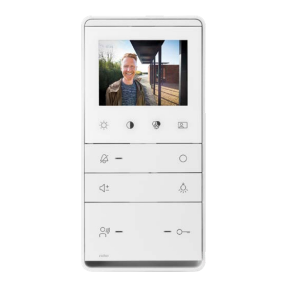
  • Seite 27 10-577 1. GERÄTEÜBERSICHT Verriegeln Anzeige-LED für Anrufe (grün) Mikrofon Abschlusswiderstand Sprechtaste 3,5-Zoll-Display (8,9 cm) Anschluss Taste zum Ein-/Ausschalten des Lichts Sensortaste zur Helligkeitseinstellung Lautsprecher Funktionstaste Sensortaste zur Kontrasteinstellung Taste zum Türöffnen Lautstärketaste Sensortaste zur Farbeinstellung Anzeige-LED für Türöffner (blau) Anzeige-LED für Stummschaltung Sensortaste für Bildauswahl...
  • Seite 28 10-577 1.1. Anzeige- und Bedienelemente Verwendung Fehleranzeige Sensortaste zur Kurz drücken: einstellbar in 8 Stufen Helligkeitseinstellung Sensortaste zur Kurz drücken: einstellbar in 8 Stufen Kontrasteinstellung Sensortaste zur Kurz drücken: einstellbar in 8 Stufen Farbeinstellung Kurz drücken: Videobild der Video-Außensprechstelle Sensortaste für Bildauswahl...
  • Seite 29: Montage Und Installation

    Kunststoff ASA Abmessungen (mm) H 194 x B 94 x T 21 mm Gewicht 227 g (einschließlich Montagedose) 6-Leitungstechnik 1.3. Höchstanzahl 10-577 Bei Verwendung von Netzteil und Steuereinheit 6-adriger Betrieb 10-801 und 10-801-05 10-806-01 2. MONTAGE UND INSTALLATION 2.1. Installation der Montagedose •...
  • Seite 30 10-577 2.2. Verkabelung Zulässiger Querschnitt (Durchmesser) pro Klemme: Max. 1,5 mm (Ø 0,32 … 1,4 mm) Max. Anzahl Adern pro Klemme: 2 x 0,8 mm, 3 x 0,6 mm • Schließen Sie die restlichen Adern mit den Hilfsklemmen an. • Führen Sie nur Anschlussleitungen, die aus dem gleichem Material bestehen und den gleichen Durchmesser haben, in einen Klemmenkontakt.
  • Seite 31 10-577 2.3. Position des Abschlusswiderstands Wenn die Video-Innensprechstelle 10-577 nicht am Ende der Leitung liegt und nicht das einzige Gerät an der Leitung ist: Steckbrücke J1 auf die beiden oberen Kontakte stecken (Werkseinstellung) Wenn die Video-Innensprechstelle 10-577 am Ende der Leitung liegt und das einzige Gerät...
  • Seite 32 • Schließen Sie den Etagentaster an die Klemmen E und P an. 12V 1A max Hinweis: Bei Verwendung der Niko-Klingeltaste 05-540 muss die Leuchte entfernt werden. 2.6. Fehlererkennung und -anzeige Fehler werden optisch und akustisch signalisiert: Ein Fehlersignal ertönt und beide LEDs blinken durchgängig.
  • Seite 33 10-577 2.8. Verkabelungsdiagramm für das Beispiel der Konfiguration 6-Drahttechnik HINWEIS: Setzen Sie den Abschlusswiderstand, a b E P M C V1 V2 wenn das Gerat am Ende eines BUS Videostranges installiert ist. Etagentaster Video- Innenstation 10-577 Etagentaster Video- Innenstation a b E P M C V1 V2...
  • Seite 34 10-577 3. KONFIGURATION 3.1. Konfigurationsmöglichkeiten Die Video-Innensprechstelle kann auf 3 Arten programmiert werden: manuell, mit dem Servicegerät 10-870 oder mit der Niko-Konfigurationssoftware für die Zugangskontrolle (Programmierschnittstelle 10-855 wird benötigt). Niko empfiehlt die Programmierung mit der Konfigurationssoftware. Funktion Bedienungs- 10-870 Niko-Konfigurations-...
  • Seite 35: Betrieb

    10-577 3.2. Konfiguration mittels Servicegerät 10-870 Die Video-Innensprechstelle funktioniert wie eine Türsprechanlage. Bitte verwenden Sie die Befehle unter Steuerfunktion 9, um die Konfiguration zu erstellen. Türsprechanlage finden Funktionstaste Rufweiterleitung SNForw Türöffnerautomatik Interner Anruf SNInt Steuerfunktion 8 Taste zum Ein-/Ausschalten des Lichts...
  • Seite 36: Häufig Gestellte Fragen

    Die Auswahl des Ruftons endet außerdem automatisch 8 Sekunden nach letztmaligen Drücken einer Taste * Standardmäßig ist bei allen Video-Außensprechstellen derselben Rufton voreingestellt. Wenn Sie einen anderen Rufton für eine Außensprechstelle einstellen möchten, müssen Sie zuerst den „Audiogrenzwert der Video-Außensprechstelle“ ändern. Dies ist nur in der Niko-Konfigurationssoftware für die Zugangskontrolle möglich.
  • Seite 37 10-577 Die Farben des Videobildes haben Das Videosignal ist nicht stark genug. Die Anschlussleitung einer Aufputzkamera wurde keinen Kontrast. verlängert, obwohl dies nicht geschehen sollte. Die Leitungslänge zwischen zwei aktiven Videokomponenten wurde unerlaubt überschritten. Signalverluste können teilweise durch Drehknöpfe an aktiven Videokomponenten behoben werden (siehe Produktinformation der Komponenten).
  • Seite 38: Vor Installation Zu Beachtende Sicherheitshinweise

    Zusätzliche Exemplare erhalten Sie über die Website oder den Kundendienst von Niko. 7. CE-KENNZEICHNUNG Dieses Produkt erfüllt alle anwendbaren europäischen Richtlinien und Verordnungen. Für Funkgeräte erklärt Niko nv, dass die Funkgeräte aus dieser Anleitung der Richtlinie 2014/53/EU entsprechen. Falls zutreffend, kann der vollständige Text der EU-Konformitätserklärung auf www.niko.eu eingesehen werden.
  • Seite 39: Device Overview

    10-577 1. DEVICE OVERVIEW Lock Call indication LED (green) Microphone Terminal resistor Talk button 3.5’’ display Connector Light switch button Brightness touch button Speaker Function button Contrast touch button Door opener button Volume button Colour control touch button Door opener indication led (blue)
  • Seite 40 10-577 1.1. Indicators and controls Usage Error messaging Brightness touch button Press briefly: adjustable in 8 levels Contrast touch button Press briefly: adjustable in 8 levels Colour control touch button Press briefly: adjustable in 8 levels Press briefly: video image from the external video unit is...
  • Seite 41: Mounting And Installation

    Dimensions (mm) H 194 x W 94 x D 21 mm Weight 227 g (mounting box included) 6-wiring technique 1.3. Max. number 10-577 With the use of a power supply and control unit 6-wire operation 10-801 and 10-801-05 10-806-01 2. MOUNTING AND INSTALLATION 2.1.
  • Seite 42 10-577 2.2. Wiring Permitted cross section (diameter) per terminal: Max..1.5 mm (Ø 0.32 … 1.4 mm) Max. number of wires per terminal: 2 x 0.8 mm, 3 x 0.6 mm • Connect the remaining wires with the auxiliary terminals. • Only insert connection wires made of the same material and with the same diameter in a terminal contact.
  • Seite 43 10-577 2.3. Position of the terminal resistor If the internal video unit 10-577 is not at the end of the line and is not the only device on the line: place jumper J1 on the two upper contacts (factory setting)
  • Seite 44 • Connect the floor push button to the E and P terminals. 12V 1A max note: If you use the Niko bell button 05-540, you need to remove the lamp. 2.6. Error detection and error message Errors are visually and acoustically signalled: error signal sounds and both LEDS keep flashing.
  • Seite 45 Set the terminal resistor, when the device is a b E P M C V1 V2 installed at the end of a bus video line. floor push button Internal video unit 10-577 floor push button Internal video unit 10-577 a b E P M C V1 V2 floor push button...
  • Seite 46 3.1. Configuration options The internal video unit can be programmed in 3 ways: manually, with the service unit 10-870 or with the Niko configuration software for access control (programming interface 10-855 is required). Niko recommends programming with the configuration software.
  • Seite 47: Operation

    10-577 3.2. Configuration with the service unit 10-870 The internal video unit works like an intercom. Please use the commands under control function 9 to establish the configuration. Find intercom Function button Call forwarding SNForw Automatic door opener Internal call...
  • Seite 48: Frequently Asked Questions

    * By default all external video units use the same ringtone. If you want to set a different ringtone for an external unit, you need to change the “audio external video unit limit” first. This is only possible in the Niko configuration software for access control.
  • Seite 49 10-577 There is no contrast in the colours The video signal is not strong enough. The connection wire of a surface-mounted camera was of the video image. extended, even though this should not be done. The wire length between two active video components was exceeded without permission.
  • Seite 50 This user manual must be presented to the user. It should be included in the electrical installation file and it should be passed on to any new owners. Additional copies are available on the Niko website or via Niko customer services.
  • Seite 51: Prehľad Zariadenia

    10-577 1. PREHĽAD ZARIADENIA Zámok Signalizačné LED hovoru (zelená) Mikrofón Koncový rezistor Tlačidlo na komunikáciu 3,5" displej Konektor Tlačidlo na spínanie osvetlenia Dotykové tlačidlo na nastavenie jasu Reproduktor Funkčné tlačidlo Dotykové tlačidlo na nastavenie kontrastu Tlačidlo otvárania dverí Tlačidlo na ovládanie hlasitosti Dotykové...
  • Seite 52 10-577 1.1. Indikátory a ovládače Použitie Chybové hlásenia Krátko stlačte: nastaviteľné na 8 úrovniach Krátko stlačte: nastaviteľné na 8 úrovniach Kontrast Dotykové tlačidlo na Krátko stlačte: nastaviteľné na 8 úrovniach nastavenie farby. Dotykové tlačidlo na výber Krátko stlačte: zobrazí sa obraz videa z vonkajšej video obrazu jednotky alebo budete prepínať...
  • Seite 53 Rozmery (mm) V 194 x Š 94 x H 21 mm Hmotnosť 227 g (vrátane montážnej krabice) 6-vodičová technika áno 1.3. Max. kat. číslo 10-577 So zdrojom napájania a ovládacej jednotky 6-vodičová technika 10-801 a 10-801-05 10-806-01 2. MONTÁŽ A INŠTALÁCIA 2.1.
  • Seite 54 10-577 2.2. Zapojenie Povolený prierez (priemer) na kontakt svorkovnice: Max.: 1,5 mm (Ø 0,32 … 1,4 mm) Max. počet vodičov na kontakt svorkovnice: 2 x 0,8 mm, 3 x 0,6 mm • Zvyšné vodiče pripojte pomocou dodatočných svorkovníc. • Do kontaktu svorkovnice zasúvajte len vodiče s rovnakým priemerom vyrobené...
  • Seite 55 10-577 2.3. Poloha koncového rezistora Ak vnútorná video jednotka 10-577 nie je na konci linky a je to jediné zariadenie na linke: umiestnite prepojku J1 na dva horné kontakty (továrenské nastavenia) Ak vnútorná video jednotka 10-577 je na konci linky alebo je to jediné...
  • Seite 56 • Pripojte tlačidlo zvončeka na poschodí k svorkám E a P. 12V 1A max pozn.: Ak používate tlačidlo zvončeka od spoločnosti Niko 05-540, musíte odstrániť žiarovku. 2.6. Detekcia chýb a chybové hlásenia Chybové hlásenia majú akustické a vizuálne signalizačné prvky: pri chybových hláseniach budete počuť akustické signály a LED kontrolky budú blikať.
  • Seite 57 Nastavte koncovy odpor až vtedy, a b E P M C V1 V2 keď zariadenie bolo nainštalovane na koniec BUS video obvodu. Tlačidlo poschodia Interna video jednotka 10-577 Tlačidlo poschodia Interna video jednotka 10-577 a b E P M C V1 V2 Tlačidlo poschodia...
  • Seite 58 10-577 3. KONFIGURÁCIA 3.1. Možnosti konfigurácie Vnútornú video jednotku je možné naprogramovať 3 spôsobmi: manuálne, pomocou servisnej jednotky 10-870 alebo pomocou Niko konfiguračného softvéru pre vstupové systémy (budete potrebovať programovacie rozhranie 10-855). Spoločnosť Niko odporúča programovať pomocou konfiguračného softvéru. Funkcia Návod...
  • Seite 59 10-577 3.2. Konfigurácia pomocou servisnej jednotky 10-870 Vnútorná vide jednotka funguje ako komunikačné zariadenie (intercom) Použite príkazy z ovládacej funkcie 9 na nakonfigurovanie. Nájsť intercom Funkčné tlačidlo Presmerovanie hovoru SNForw Automatický elektrický zámok Vnútorný hovor SNInt Ovládacia funkcia 8 Tlačidlo na spínanie (ZAP/VYP) osvetlenia Vnútorný...
  • Seite 60: Často Kladené Otázky

    * V prednastaveniach všetky vonkajšie video jednotky používajú to isté zvonenie. Ak chcete pre vonkajšiu jednotku nastaviť iné zvonenie, musíte najprv zmeniť „audio limity vonkajšej video jednotky“. Toto je možné iba pomocou konfiguračného softvéru od spoločnosti Niko pre vstupové systémy.
  • Seite 61 10-577 Farby video obrazu nemajú žiaden Video signál nie je dostatočne silný. Pripojovací vodič kamery na povrchovú montáž bol kontrast. predĺžený, i keď by sa to nemalo robiť. Dĺžka vodiča medzi dvomi aktívnymi video komponentmi bola presiahnutá bez príslušného povolenia.
  • Seite 62: Upozornenia Týkajúce Sa Inštalácie

    7. OZNAČENIE ES Tento výrobok spĺňa všetky relevantné Európske predpisy a nariadenia. Čo sa rádiových zariadení týka, spoločnosť Niko nv vyhlasuje, že rádiové zariadenia v tomto návode sú v súlade so smernicou 2014/53/EÚ. V prípade potreby môžete plné znenie Európskeho vyhlásenia o zhode nájsť na stránke www.niko.eu.
  • Seite 64 10-577 PM010-57700R20451...

Inhaltsverzeichnis