Inhaltsverzeichnis
Werbung
Verfügbare Sprachen
Verfügbare Sprachen
Quicklinks
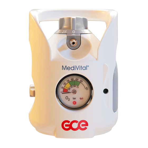
MediVital®E
PRESSURE REGULATORS INTEGRATED
WITH CYLINDER VALVES
REDUKČNÍ VENTILY S INTEGROVANÝM
UZAVÍRACÍM VENTILEM PLYNOVÝCH LAHVÍ
DRUCKREGLER MIT FLASCHENVENTILEN
REGOLATORI DI PRESSIONE
CON VALVOLA DELLA BOMBOLA INTEGRATA
INSTRUCTION FOR USE
NÁVOD K POUŽITÍ
BEDIENUNGSANLEITUNG
ISTRUZIONI PER L'USO
GCE VALVES
EN
CS
DE
IT
Werbung
Inhaltsverzeichnis

Verwandte Anleitungen für GCE MediVital E


Inhaltszusammenfassung für GCE MediVital E
- Seite 1 GCE VALVES MediVital®E PRESSURE REGULATORS INTEGRATED WITH CYLINDER VALVES REDUKČNÍ VENTILY S INTEGROVANÝM UZAVÍRACÍM VENTILEM PLYNOVÝCH LAHVÍ DRUCKREGLER MIT FLASCHENVENTILEN REGOLATORI DI PRESSIONE CON VALVOLA DELLA BOMBOLA INTEGRATA INSTRUCTION FOR USE NÁVOD K POUŽITÍ BEDIENUNGSANLEITUNG ISTRUZIONI PER L'USO...
-
Seite 2: Intended Use
(anaesthetic devices, ventilating devices, incubators etc.) or for direct gas supply to a patient’s breathing mask or cannula. GCE Combination Valves are intended to be used with the following medical gases: • Oxygen •... - Seite 3 Before the first use the product shall be kept in its original package. If removed from service (for transport, storage) GCE recommends using the original package (including inner packing materials). National laws, rules and regulations for medical gases, accident prevention and environmental protection must be observed.
-
Seite 4: Product Description
4. PERSONNEL INSTRUCTIONS The Medical Devices Directive 93/42/EEC states that the product provider must ensure that all personnel using the product are provided with the instructions & performance data. Do not use the product without properly familiarization of the product and its safe operation as defined in this Instruction for use. - Seite 5 Marking detail Total weight allowance of the Inlet connection package type Filling port type End of lifetime Inlet pressure Reference number Compliance with 93/42 EEC Serial number Compliance with 2010/35 EU A – INLET STEM The combination valve is fitted to a gas cylinder by a threaded inlet stem. The inlet stem can be taper threaded or parallel threaded with different sizes depending on the cylinder size and material.
-
Seite 6: Device Description
Movement of the flow outlet ‘G’ is normal due to the method of fixing in the main body. It does not indicate a faulty flow outlet. H – PRESSURE OUTLET OR QUICK COUPLER (OPTION) The combination valve may be fitted with a pressure outlet. The pressure outlet is supplied with gas direct from the low-pressure part of the combination valve and it is fitted with a gas specific medical quick coupling connector also called a “quick coupler”. - Seite 7 5.1.1.2. General description The E-GAUGE is used to show information about the pressure inside the gas cylinder and about the remaining time of the gas supply - until the complete exhaustion of gas cylinder - at the actually set flow (flow head outlet use only). A –...
- Seite 8 2D code The 2D code is intended for connecting the E-GAUGE with a mobile application more easily.. Using Bluetooth communication. The 2D code keeps information about MAC address of E-GAUGE for filling stations or maintenance purposes. Indication of "cylinder volume" parameter related to the E-GAUGE setup.
- Seite 9 Deep sleep mode – low consumption of electrical energy If the Medivital®E has not been in use for an extended period (10 - 20 hours typically) and actual pressure in cylinder is more than 15 bar at the same time. If the Medivital®E has not been in use for an extended period (10 - 20 hours typically) and actual pressure in cylinder is less than 15 bar at the same time.
- Seite 10 5.1.2. VISUAL AND ACOUSTIC WARNINGS Warning alarms are divided into two groups: 5.1.2.1. Operational alarms - related to the general use of the device. These are marked with a warning triangle in the top part of the display. Low pressure - first warning •...
- Seite 11 The PS (pressure sensor) is indicate. • The bar chart is not indicated. • Discontinue the cylinder from service immediately and send it back to the owner of the filling station. Service must be performed by a GCE certified service centre. 11/108...
- Seite 12 • Discontinue the cylinder from service immediately and send it back to the owner of the filling station. Service must be performed by a GCE certified service centre. No flow • A warning is indicated if the selected position of the control flow head is >...
-
Seite 13: Use Of Product
The total weight of the package as marked on the combination valve must not be exceeded if the GCE guard is used, the guard does not comply with EN ISO 11117 or no guard is used. Note: Total weight of the package includes the weight of the combination valve, the weight of the cylinder filled with gas to max. - Seite 14 Android operating system. 6.1.3.2. Description of the mobile application Starting the mobile application Start the GCE eGauge mobile application by clicking the appropriate icon. This icon will appear on the mobile device desktop after successful installation. The application will require access to the camera and Bluetooth enabled.
- Seite 15 Display the MAC address of the loaded E-GAUGE Press the "Connect key" to establish the connection between the GCE E-GAUGE mobile application and the E-GAUGE. The connection can be delayed, the key name changes to "Connecting" while waiting. Upon successful connection the window "E-GAUGE paired"...
- Seite 16 (MAC) address of the electronics. The selected device is highlighted in red. To connect the GCE eGauge application to an E-GAUGE, press the "Connect" key. The connection is delayed, during the idle period the key name changes to "Connecting".
- Seite 17 History Table of current values of cylinder re-fill and battery exchange counters "Back" key to return to the previous screen User parameterization of the E-GAUGE Here you can enter the user parameters of the E-GAUGE Volume of cylinder [litres] to which the valve is mounted Pressure units [bar/kPa/psi] "Reset parameters"...
- Seite 18 Check the combination valve and filling adaptor for contamination. If needed proceed with cleaning procedure according to chapter 8. • Check that the service or the total lifetime of the GCE product and gas cylinder has not been exceeded. •...
- Seite 19 6.1.4.3. Fitting the filling adaptor • Connect the filling adaptor using a max. tightening torque of 3,5 Nm. To prevent damage to the combination valve, the pressure inside the combination valve must be vented according to 6.1.4.2 before fitting the filling adaptor. A pneumatic or electric wrench can be used with some types of filling adaptors.
- Seite 20 • After completing the of tests according to appendix No. 3, return the filling port´s protective cover. Use only the original GCE protective cover. Pressure in the filling connections when disconnecting the filling adaptor or opening the shut- off valve of the combination valve may cause personnel injury or damage to the combination valve or filling adaptor.
-
Seite 21: Before Use
Place the filling port´s protective cover back on the combination valve with the gas cylinder pack and store in a way to prevent damage during storage and handling. Use only genuine GCE filling adaptors. Other filling adaptors may damage the non-return valve in the filling port and affects the safety of the product. -
Seite 22: After Use
Always ensure that the flow control head has been correctly set and not placed between two settings. Th flow control head placed between settings will not deliver the correct flow of medical gas. In case any visual or acoustic warnings are indicated, follow the instructions in the table - see chapt. -
Seite 23: Product Lifetime
Other user accessories: • bed hanger, humidifier holder. Accessories for filling stations: • filling adaptor. Before connecting any accessory or medical device to the combination valve, always check that they are fully compatible with connection features & performances of the product. 8. -
Seite 24: Preventive Maintenance
Use only genuine GCE components. Any product sent back to GCE (or a GCE authorised centre) for repair or maintenance shall be properly packaged to prevent contamination or damage during storage, transportation and handling. -
Seite 25: Technical Description
9.5. ENVIRONMENT There are not any know risks related to disposing the of Medivital®E device at the end of its lifetime. The battery and electronics must be disposed of in a special recycling centre. Other components may be disposed of in a standard way. 10. -
Seite 26: Warranty
12. WARRANTY The Standard Warranty period is two years from date of receipt by the GCE Customer (or if this is not known 2 years from time of the product manufacture shown on the product). The standard warranty is only valid for products handled according to Instruction for use (IFU) and general industry good practice and standards. - Seite 27 No. 1 – Technical and performance data No. 2 – Quick-coupler features and connecting/disconnecting procedure No. 3 – Post Filling Checks MANUFACTURER: GCE, s.r.o. Tel: +420 569 661 111 Zizkova 381 Fax: +420 569 661 602 583 01 Chotebor http://www.gcegroup.com Czech Republic © GCE, s.r.o. 27/108...
-
Seite 28: Účel Použití
Tyto kombinované ventily s tlakovou lahví tvoří sestavy, které slouží buď jako zdroj plynu pro zdravotnická zařízení (anesteziologické přístroje, ventilační přístroje, inkubátory, atd.) anebo k přímému dávkování plynu do inhalační masky nebo kanyly pacienta. GCE kombinované ventily jsou určené k použití s následujícími medicinálními plyny: • kyslík;... - Seite 29 Výrobek, včetně příslušenství, používejte pouze v dobře odvětrávaných prostorech. Před prvním použitím musí být výrobek ve svém originálním obalu. V případě stažení z provozu (pro přepravu, skladování) doporučuje GCE použít originální balení (včetně vnitřních výplňových materiálů). Musí být dodržovány národní zákony, vyhlášky a předpisy pro medicinální plyny, bezpečnost práce a ochranu životního prostředí.
-
Seite 30: Popis Výrobku
4. INSTRUKTÁŽ PRACOVNÍKŮ Dle medicinální direktivy 93/42/EHS má poskytovatel zařízení povinnost poskytnout všem uživatelům a osobám manipulujícím s výrobkem návod k použití & technickou dokumentaci. Nepoužívejte výrobek bez řádného seznámení s výrobkem a jeho bezpečným provozem, jak je popsáno v tomto návodu k použití. Zajistěte, aby měl uživatel odpovídající informace a znalosti požadované... - Seite 31 Detail značení Celková hmotnost Typ vstupního sestavy s lahví připojení Typ plnícího Doba konce portu životnosti Vstupní tlak Objednávací číslo Značka shody s 93/42 EEC Sériové číslo Značka shody s 2010/35 EU A – VSTUPNÍ PŘÍPOJKA Výrobek je připojen k tlakové lahvi pomocí vstupní přípojky se závitem. Přípojka může mít kuželový...
- Seite 32 H – TLAKOVÝ VÝSTUP NEBO RYCHLOUPÍNACÍ SPOJKA (VOLITELNÁ VÝBAVA) Kombinovaný ventil může být osazen tlakovým výstupem. Ten je přímo napojen do nízkotlaké části ventilu a je osazen specifickou rychloupínací spojkou, nazývanou také „rychlospojka“. Uživatel může připojit další zařízení k výstupu plynu pomocí speciálního protikusu - rychlospojkového nástavce (viz příloha č.2).
- Seite 33 5.1.1.2. Obecný popis E-GAUGE zobrazuje informace o tlaku plynu v lahvi a o zbývajícím čase do vyprázdnění tlakové láhve při daném průtoku (pouze při použití výstupu z průtokové hlavy). A – ELEKTRONIKA Elektronika E-GAUGE je umístěna v plastovém krytu. Pro zobrazování provozních informací je použitý...
- Seite 34 2D kód 2D kód je určen pro snadnější připojení E-GAUGE s mobilní aplikací pomocí Bluetooth komunikce pro účely nastavení parametrů v plnicí stanici nebo pro servisní účely. 2D kódu je uložena informace o MAC adrese elektroniky. Zobrazení parametru „objem lahve“ v litrech, na kterou je E-GAUGE nastaven.
- Seite 35 Bezpečnostní kód Pokud jsou pomocí mobilní aplikace měněny parametry „objem lahve“ a „jednotky tlaku“, je úspěšné uložení nových parametrů podmíněno zadáním 4-místného kódu vygenerovaného na displeji E-GAUGE do zadávacího pole v mobilní aplikaci (viz. kap. 6.1.3 ) Režim hlubokého spánku – režim nízké spotřeby elektrické energie Pokud je Medivital®E dlouhodobě...
- Seite 36 5.1.2. VIZUÁLNÍ A AKUSTICKÁ VAROVÁNÍ Varovné signály jsou rozděleny do dvou skupin 5.1.2.1. Provozní signály – souvisí s běžným užíváním zařízení. Jsou označeny výstražným trojúhelníkem v horní části displeje Nízký tlak – první upozornění • V případě, že tlak plynu v lahvi poklesne pod 50 bar. •...
- Seite 37 Je zobrazen výstražný symbol PS (pressure sensor) • Bargraf není zobrazen • Vyřaďte lahev ihned z provozu a zašlete zpět majiteli nebo plnící stanici. Servis musí být provedený GCE certifikovaným servisem. Porucha měření průtoku • Varování se zobrazí v případě, poruchy snímače průtokové...
- Seite 38 Efektivní vyzařovaný výkon: max. 3 dBm Maximální vzdálenost, při které se lze bezpečně spojit mezi zařízením s nainstalovanou mobilní aplikací GCE eGauge a elektronickým manometrem je 10 metrů ve volném prostoru. V uzavřených prostorech tato vzdálenost klesá. 38/108...
-
Seite 39: Použití Výrobku
ISO 11117, musí sestava ventilu s krytem a tlakovou lahví splňovat požadavek na pádovou zkoušku podle EN ISO 10524-3. Pokud je použitý GCE kryt nebo kryt není v souladu s EN ISO 11117 případně není použitý kryt žádný, nesmí celková hmotnost sestavy s lahví přesáhnout maximální povolenou hmotnost, která... - Seite 40 Fyzikální jednotky, ve kterých bude zobrazován tlak [bar/MPa/psi] Tyto parametry mohou být nastaveny již z výroby, popř. si je může zákazník dle potřeby nastavovat či měnit pomocí mobilní aplikace GCE eGauge 6.1.3.1. Instalace mobilní aplikace GCE eGauge Vyžádejte si soubor s instalací aplikace a přístupový PIN pro možnost parametrizace E-GAUGE.
- Seite 41 Po načtení 2D kódu se aplikace automaticky vrátí na předchozí obrazovku. Spojení s načteným E-GAUGE Zobrazení MAC adresy načteného E-GAUGE. Pro připojení aplikace GCE eGauge k E-GAUGE stiskněte tlačítko „Connect“. Navazování spojení má časovou prodlevu, během které se název tlačítka změní na „Connecting“. Po úspěšném připojení je automaticky zobrazeno okno E-GAUGE spárován.
- Seite 42 E-GAUGE spárován Je-li E-GAUGE korektně spárován s mobilní aplikací, na stavovém řádku jsou zobrazeny parametry ventilu: SN: sériové číslo ventilu MAC: Síťová adresa elektroniky FW: Aktuální verze firmware nahraného v E-GAUGE. Tlačítko „Values reading“ pro přechod na obrazovku čtení aktuálních hodnot manometru. Tlačítko „Customer parameters“...
- Seite 43 STORNO – zavření zadávacího pole 6.1.4. PROCES PLNĚNÍ Při plnění dodržujte normy týkající se čistoty pro kyslíková zařízení. Používejte pouze originální nebo GCE schválené plnící adaptéry. Jiné plnící adaptéry mohou poškodit zpětný ventil v plnícím portu a ohrozit bezpečnost výrobku 6.1.4.1. Kontrola před plněním •...
- Seite 44 • Zkontrolujte, zda není ventil a plnící adaptér znečištěný. V případě potřeby proveďte čištění ventilu dle kapitoly 8. • Zkontrolujte, zda celková doba životnosti ventilu a tlakové lahve nejsou překročeny. • Pokud je ventil vybaven průtržným diskem zkontrolujte jeho neporušenost. •...
- Seite 45 • Po kompletním provedení testů dle přílohy č. 3 osaďte ventil krytkou plnícího portu. Použijte pouze originální GCE krytku. Pokud bude tlak v plnícím přívodu při odpojování plnícího adaptéru a nebo nebude uzavřený uzavírací ventil kombinovaného ventilu, hrozí vážné nebezpečí zranění obsluhy či poškození...
- Seite 46 Ventil osaďte krytkou plnícího portu a ventil i tlakovou lahev uložte a zabalte tak, aby nedošlo ke znečištění nebo poškození při skladování či manipulaci. Používejte pouze originální nebo GCE schválené plnící adaptéry. Jiné plnící adaptéry mohou poškodit zpětný ventil v plnícím portu a ohrozit bezpečnost výrobku.
-
Seite 47: Před Použitím
6.2.1. PŘED POUŽITÍM Vizuální kontrola před použitím: • Zkontrolujte, zda není ventil poškozený (včetně štítků a značení). Pokud má znaky poškození, stáhněte jej z provozu a vhodně označte jeho stav. • Zkontrolujte, zda ventil není znečištěný. V případě potřeby proveďte čištění ventilu dle kapitoly 8. - Seite 48 6.2.2.2. Použití tlakového výstupu ventilu • Zajistěte, aby byl ovladač průtoku v pozici “0” (pokud jím je ventil vybaven). • Otočením ručního kolečka proti směru hodinových ručiček pomalu otevřete uzavírací ventil kombinovaného ventilu. K plnému otevření dojde cca po 1 otáčce ovladače, plné otevření je indikováno dle obrázku v kapitole 5.
- Seite 49 “Směrnice Evropského parlamentu a Rady 2006/12/ES ze dne 5. dubna 2006 o odpadech“. V souladu s článkem 33 nařízení REACH se společnost GCE, s.r.o. jako odpovědný výrobce zavazuje informovat všechny zákazníky, pokud materiály obsahují 0,1 % nebo více látek uvedených na seznamu látek vzbuzujících velmi velké...
-
Seite 50: Technický Popis
Pro informace o servisu ve vašem okolí prosím kontaktujte GCE nebo distributora GCE výrobků. Opravy kombinovaných ventilů GCE, které nemusí být prováděny certifikovanou osobou pro opravy, se týkají výměny následujících poškozených součástek: •... - Seite 51 10.1. EMC PODMÍNKY Kombinovaný ventil Medivital®E je vhodný pro použití v domácnostech, nemocnicích, ambulancích apod. Vyvarujte se použití v blízkosti zařízení s vysokou intenzitou elektromagnetického rušení, jako je magnetická rezonance, VF chirurgické nástroje apod. Zařízení neobsahuje žádné kabely či převodníky, které by vedly ke zvýšení EM emisí či ke snížení EM odolnosti zařízení. Nezbytná...
- Seite 52 12. ZÁRUKA Běžná záruční doba na výrobek je dva roky od data doručení výrobku zákazníkům GCE (pokud není datum doručení známo, počítá se záruční doba od data uvedeného na výrobku). Běžná záruka je platná pouze na výrobky, které jsou používány dle návodu k použití, předepsaných norem a správné...
- Seite 53 Gasflasche eine Einheit, die entweder als Gasquelle für Medizingeräte (Anästhesiegeräte, Beatmungsgeräte, Inkubatoren) oder für die direkte Gaszufuhr zur Atemmaske oder Nasenbrille eines Patienten eingesetzt werden. Die Kombiventile von GCE sind zur Verwendung in Verbindung mit folgenden medizinischen Gasen bestimmt: •...
-
Seite 54: Sicherheitsanforderungen Für Betrieb, Transport Und Lagerungs
Das Produkt und die zugehörigen Geräte nur in gut gelüfteten Räumen einsetzen. Vor Erstinbetriebnahme muss sich das Produkt in seiner Originalverpackung befinden. Im Falle der Außerbetriebsetzung (für Transport, Lagerung) empfiehlt GCE die Originalverpackung anzuwenden. Es sind die nationalen Gesetze, Regelungen und Vorschriften zu Unfallverhütung und Umweltschutz beim Einsatz von medizinischen Gasen zu beachten. -
Seite 55: Anweisungen Für Mitarbeiter
Für Kombiventile, die zur Verwendung mit einem Mischgas aus O O vorgesehen sind, liegt die niedrigste Betriebstemperatur bei +5 °C. Beim bestimmungsgemäßen Gebrauch kann sich auf der Oberfläche des Kombiventils eine leichte Frostschicht ablagern. Dies wird dadurch verursacht, dass die Temperatur des Gases durch eine Drosselung des Drucks sinkt (Joule-Thomson-Effekt). -
Seite 56: Produktbeschreibung
5. PRODUKTBESCHREIBUNG Das Kombiventil verbindet die Funktionen von Hochdruck-Gasflaschenventilen und medizinischen Druckreglern für medizinische Gase. Das aus der Flasche austretende Gas strömt zunächst durch das Haupt-Absperrventil, anschließend durch den Druckregler und wird schließlich über einen Flow- oder Druckanschluss dem Patienten zugeführt. Der Ausgangsdruck ist werksseitig fest eingestellt und jedes Kombiventil ist zum Schutz bei einem Versagen des Druckreglers mit einem Unterdruckentlastungsventil ausgestattet. - Seite 57 A – ANSCHLUSSSTUTZEN Das Kombiventil wird mit einem Gewinde-Anschlussstutzen in die Gasflasche eingedreht. Der Anschlussstutzen ist entweder mit einem konischen oder einem zylindrischen Gewinde ausgestattet und in verschiedenen Größen (für verschiedene Flaschengrößen und -materialien) erhältlich. B – FÜLLANSCHLUSS A Der Füllanschluss dient dem Füllen der Gasflasche an einer Füllstation; sie hat keine patientenrelevante Funktion.
-
Seite 58: Elektronischer Anzeiger E-Gauge
J – ÜBERSTRÖMVORRICHTUNG ODER STEIGROHR (OPTIONAL) Die Überströmvorrichtung gewährleistet die sichere Entlüftung von Gasen aus der Gasflasche im Falle eines Bruchs des Kombiventils über oberhalb des Anschlussstutzens (z. B. wenn die Flasche umfällt und beschädigt wird). Das Steigrohr bietet keine derartige Funktion. Die Überströmvorrichtung und das Steigrohr sollen verhindern, dass Verunreinigungen aus der Flasche in das Kombiventil gelangen. - Seite 59 A – ELEKTRONIK Elektronik Anzeigers Kunststofffach untergebracht. Für die Anzeige der Betriebsinformationen wird das LCD-Display angewandt. B – LAGESENSOR DES DURCHFLUSSKOPFES Innenraum Steuergeräts Lagesensor des Durchflusskopfes installiert, der für die Ermittlung des aktuellen eingestellten Durchflusses für die Berechnung der Zeit der Gasversorgung vorgesehen ist.
- Seite 60 2D Code Der 2D-Code dient dazu, das E-GAUGE einfacher mit einer mobilen Applikation zu verbinden, unter Verwendung der Bluetooth-Kommunikation. Der 2D-Code enthält Informationen zur MAC-Adresse vom E-GAUGE für Zwecke der Parametereinstellung in der Füllstation oder für Servicezwecke. Anzeige des Parameters "Flaschenvolumen" in Bezug auf das E-GAUGE-Setup.
- Seite 61 Sicherheitscode Wenn durch mobile Applikation Parameter „Flaschenvolumen“ und „Druckeinheiten“ geändert werden, wird die erfolgreiche Speicherung neuer Parameter durch die Eingabe des 4-stelligen Codes bedingt, der am Display des E-GAUGE im Eingabefeld in der mobilen Applikation generiert wird (siehe Kap. 6.1.3 ) Tiefschlafmodus - geringer Stromverbrauch Wenn das Medivital®E für eine längere Zeit nicht verwendet wurde (normalerweise 10 bis 20 Stunden) und der...
-
Seite 62: Visuelle Und Akustische Warnungen
Die am Display angezeigte restliche Zeit ist um 5-10% kürzer (abhängig von der Temperatur, Flaschengröße), als Realzeit, während der der aktuelle Flascheninhalt bei konstantem Durchfluss abgelassen wird. Durch diese Tatsache hat der Patient eine ausreichende Sicherheitszeitreserve. 5.1.2. VISUELLE UND AKUSTISCHE WARNUNGEN Visuelle und akustische Warnungen 5.1.2.1. - Seite 63 • Das Warnsymbol PS (pressure sensor) wird angezeigt • Das Balkendiagramm wird nicht angezeigt • Die Flasche sofort außer Betrieb setzen und zurück an den Besitzer oder die Füllstation senden Der Service muss durch GCE zertifizierte Stelle durchgeführt werden. 63/108...
- Seite 64 Das Warnsymbol FS (flow sensor) wird angezeigt • Die Flasche sofort außer Betrieb setzen und zurück an den Besitzer oder die Füllstation senden Der Service muss durch GCE zertifizierte Stelle durchgeführt werden. Kein Durchfluss • Die Warnung wird dann angezeigt, wenn mittels Steuergerät des Durchflusskopfes der Gasdurchfluss >...
-
Seite 65: Verwendung Des Produkts
Sektor) Effektive abgestrahlte Leistung: max. 3 dBm Maximaler Abstand für die sichere Verbindung der Anlage mit der installierten Applikation GCE eGauge und dem E-GAUGE beträgt 10 Meter im Freien. In geschlossenen Räumlichkeiten wird dieser Abstand reduziert. 6. VERWENDUNG DES PRODUKTS 6.1. -
Seite 66: Einstellung Des E-Gauge
Quellen installieren" im Android-Betriebssystem aktivieren. 6.1.3.2. Beschreibung der mobilen Applikation Mobile Applikation starten Starten Sie die mobile GCE eGauge-App, indem Sie auf das entsprechende Symbol klicken. Diese wird nach erfolgreicher Installation auf dem Desktop des mobilen Geräts angezeigt. Die Applikation erfordert Zugriff auf die Kamera und die aktivierte Bluetooth-Funktion. - Seite 67 Bildschirm zurück Verbindung mit dem eingelesenen E-GAUGE Anzeige der MAC Adresse des eingelesenen E-GAUGE Um die GCE eGauge-App mit dem E-GAUGE zu verbinden, drücken Sie die "Connect" -Taste. Die Herstellung der Verbindung hat eine Zeitverzögerung, während der der Name der Taste in "Connecting"...
- Seite 68 Seriennummer des Ventils und die Netzwerkadresse (MAC) der Elektronik identifiziert Das gewünschte Gerät wird nach dem Drücken rot markiert Um die GCE eGauge-App mit dem E-GAUGE zu verbinden, drücken Sie die "Connect" -Taste. Die Herstellung der Verbindung hat eine Zeitverzögerung, während der der Name der Taste in "Connecting"...
- Seite 69 Historie Tabelle der aktuellen Zählerwerte von Flaschenfüllung und Batteriewechsel „Back“ Taste zur Rückkehr zum vorangehenden Bildschirm Benutzerparametrierung des elektronischen Manometers Hier werden die Benutzerparameter des E-GAUGE eingegeben Flaschenvolumen in Liter, für das das Ventil montiert ist Druckeinheiten [bar/kPa/psi] Taste “Reset parameters” zur Löschung der bestehenden Benutzerparameter Taste “Save parameters”...
- Seite 70 Kombiventil und Fülladapter auf Verunreinigungen überprüfen. Bei Bedarf mit dem Reinigungsverfahren gemäß Kapitel 8 fortfahren. • Sicherstellen, dass die Einsatzdauer bzw. Gesamt-Lebensdauer des GCE Produkts und der Gasflasche nicht überschritten werden. • Ist eine Berstscheibe im Kombiventil enthalten, überprüfen Sie diese auf Beschädigungen.
- Seite 71 • Das Absperrventil wieder schließen (im Uhrzeigersinn, handfest, kein Werkzeug verwenden). Das maximale Anziehmoment von 5 Nm nicht überschreiten. • Den Flow-Regler in die Stellung „0“ drehen. B. Entlüften der Gasflasche über den Druckanschluss: • Das Handrad am Absperrventil langsam vollständig öffnen (etwa 1 Umdrehung gegen den Uhrzeigersinn, siehe Abbildung in Kapitel 5).
-
Seite 72: Kontrolle Der Richtigen Funktion Des E-Gauge Nach Flaschenfüllung
Abflachungen des Kombiventils ansetzen. Die Schlüsselweite beträgt 26 mm. • Die Verschlusskappe wieder am Füllanschluss anbringen. Das Kombiventil so verstauen, dass Schäden bei der Lagerung vermieden werden. Nur Original-Fülladapter von GCE verwenden. Andere Fülladapter können das Rückschlagventil Füllanschluss beschädigen... -
Seite 73: E-Gauge - Batteriewechse
Ein zu schnelles Öffnen des Ventils kann zu Feuer- und Explosionsgefahr aufgrund austretenden Gases führen. Ein unzureichendes Öffnen des Absperrventils kann zu einer zu geringen Gasabgabe führen. 6.1.7. E-GAUGE - BATTERIEWECHSE Falls am Display das Symbol der entladenen Batterie angezeigt wird (siehe Kap. 5.1.2.2), muss die Batterie durch ordentlich und nachweislich eingeschultes Personal gemäß... -
Seite 74: Nach Dem Einsatz
Ein zu schnelles Öffnen des Ventils kann zu Feuer- und Explosionsgefahr aufgrund austretenden Gases führen. Ein unzureichendes Öffnen des Absperrventils kann zu einer zu geringen Gasabgabe führen. Stets sicherstellen, dass der Flow-Regler einrastet und sich nicht zwischen zwei Einstellungen befindet. Befindet sich der Flow-Regler zwischen zwei Einstellungen, wird das medizinische Gas nicht in der korrekten Menge abgegeben. -
Seite 75: Service, Produktlebensdauer Und Wartung
7. ZUBEHÖR Zubehör, das an den Flow-Anschluss angeschlossen werden kann: • Schläuche von Atemmasken, Nasenbrillen oder Befeuchter. Zubehör, das an den Druckanschluss angeschlossen werden kann: • Niederdruck-Schläuche (Arbeitsdruck >10 bar), Flowmeter, Venturi-Absaugeinheiten, Lungenbeatmungsgeräte. Sonstige Zubehörteile: • Aufhängung für Krankenbetten, Befeuchterhalter. Zubehör für Füllstationen: •... -
Seite 76: Vorbeugende Wartung
Um weitere Informationen zu den in Ihrem Land verfügbaren Wartungsleistungen zu erhalten, setzen Sie sich bitte mit GCE oder dem für Ihr GCE Produkt zuständigen Vertriebshändler in Verbindung. Normalerweise kann das Kombiventil repariert werden, während es an der Gasflasche montiert ist. -
Seite 77: Emc-Bedingungen
Alle zur Reparatur oder Wartung an GCE (oder autorisierte GCE Zentren) eingesandten Produkte sind ordnungsgemäß zu verpacken, um Verunreinigungen oder Beschädigungen bei der Lagerung, beim Transport und bei der Handhabung zu vermeiden. Für Reparaturen ist eine kurze Fehler- oder Störungsbeschreibung sowie die Angabe einer Vorgangsnummer vorteilhaft. - Seite 78 MediVital®E sollte nicht in der Nähe anderer Anlagen angewandt oder an diesen Anlagen installiert werden. Wenn dies nicht vermieden werden kann, sollte das Ventil mit dem E-GAUGE im Normalbetrieb in der jeweiligen Zusammensetzung und Konfiguration geprüft werden. MediVital®E sollte neben oder in einem Block mit anderen Geräten nicht verwendet werden, da dies zu Fehlfunktionen führen kann.
-
Seite 79: Gewährleistung
Abfall werfen. 12. GEWÄHRLEISTUNG Die Standard Garantiezeit beträgt zwei Jahre ab dem Datum des Warenempfangs beim GCE Kunden (oder falls das nicht ermittelbar ist, ab dem Produktionsdatum welches auf der Ware ausgewiesen ist.) Die Standard Garantiezeit ist nur gültig für Waren, die entsprechend der Bedienungsanleitung und der generell gültigen Praxis und Normen der Industrie gehandhabt... - Seite 80 č. 2: Quick-coupler features and connecting/disconnecting procedure (=Postup připojování a odpojování tlakového výstupu) č.3: Zkoušky po plnění HERSTELLER: GCE, s.r.o. Tel: +420 569 661 111 Zizkova 381 Fax: +420 569 661 602 583 01 Chotebor http://www.gcegroup.com Tschechische Republik © GCE s.r.o 80/108...
-
Seite 81: Uso Previsto
(dispositivi anestetici, dispositivi di ventilazione, incubatrici, ecc.) o per l'approvvigionamento di gas diretto alla maschera di respirazione o cannula di un paziente. Le valvole combinate GCE sono destinate ad essere utilizzate con i seguenti gas medicali: • Ossigeno •... - Seite 82 Prima del primo utilizzo, il prodotto deve essere conservato nella sua confezione originale. Se messo fuori servizio (per il trasporto, lo stoccaggio) GCE consiglia di utilizzare il pacchetto originale (compresi i materiali di imballaggio interni). Devono essere rispettate le leggi nazionali, le norme e i regolamenti per i gas medicali, la prevenzione degli infortuni e la tutela dell'ambiente.
-
Seite 83: Descrizione Del Prodotto
4. ISTRUZIONI DEL PERSONALE La direttiva sui dispositivi medici 93/42/CEE stabilisce che Il fornitore del prodotto deve assicurare vengano forniti istruzioni per l'uso e dati sulle prestazioni dello stesso a tutto il personale addetto alla sua manipolazione. Non utilizzare il prodotto senza una corretta formazione ed un utilizzo sicuro dello stesso come definito nel presente documento “Istruzione per l'uso”. - Seite 84 Dettagli di marcatura Tipo di Peso totale del pacco connessione di ingresso Tipo di presa di Fine del ciclo riempimento di vita Pressione di ingresso Numero di Conforme alla riferimento direttiva 93/42/ Numero di serie Conforme alla direttiva 2010/35/ A – RACCORDO DI INGRESSO La valvola combinata è...
-
Seite 85: Descrizione Del Dispositivo
L'uscita del flusso "G" è dotata di raccordo mediante tubo flessibile o di tipo filettato (per gli accessori da collegare tramite collegamento filettato). Il movimento dell'uscita del flusso "G" è normale a causa del metodo di fissaggio nel corpo principale. Non indica che l'uscita del flusso è difettosa. H –... - Seite 86 5.1.1.2. Descrizione generale Il E-GAUGE viene utilizzato per visualizzare informazioni riguardo la pressione all'interno della bombola e circa il tempo rimanente della fornitura del gas, fino al completo esaurimento della bombola di gas, al flusso effettivamente impostato (uso della sola uscita della testina del flusso). A –...
- Seite 87 Codice 2D Il codice 2D è progettato per collegare più facilmente E-GAUGE un'applicazione mobile utilizzando comunicazione Bluetooth. Il codice 2D archivia le informazioni sull'indirizzo MAC dell'indicatore E-GAUGE per le stazioni di rifornimento o per scopi di manutenzione. Indicazione del parametro "capacità della bombola" relativo alla configurazione de E-GAUGE.
- Seite 88 Modalità di sospensione profonda - basso consumo di energia elettrica Se Medivital®E non è stato utilizzato per un lungo periodo (in genere 10-20 ore) e, allo stesso tempo, la pressione effettiva nella bombola è superiore a 15 bar. Se Medivital®E non è stato utilizzato per un lungo periodo (in genere 10-20 ore) e, allo stesso tempo, la pressione effettiva nella bombola è...
- Seite 89 Bassa pressione - primo avvertimento • Nel caso la pressione della bombola scenda sotto i 50 bar. • Lo sfondo del display diventa nero. • Il simbolo di avvertimento è visualizzato • Il segnale acustico inizia contemporaneamente con il lampeggio dei diodi LED rossi sulla sinistra del display. Bassa pressione - secondo avvertimento •...
- Seite 90 Mettere immediatamente fuori servizio la bombola e rinviarla al proprietario della stazione di riempimento. Il servizio deve essere eseguito da un centro di assistenza certificato GCE. Errore della misura del flusso • Viene visualizzato un avvertimento in caso di difetto del sensore della testina del flusso, di disconnessione o se la testina di controllo del flusso è...
- Seite 91 Potenza di radiazione effettiva: max. 3 dBm La distanza massima per il collegamento sicuro tra il dispositivo con applicazione mobile installata GCE eGauge e il E-GAUGE è di 10 metri in uno spazio aperto. In spazi chiusi questa distanza si riduce.
-
Seite 92: Utilizzo Del Prodotto
EN ISO 10524-3. Il peso totale del pacchetto, come indicato sulla valvola combinata, non deve essere superato se si utilizza la protezione GCE, la protezione non è conforme alla norma EN ISO 11117 o non viene utilizzato nessuna protezione. - Seite 93 Unità fisiche in cui deve essere visualizzata la pressione [bar/MPa/psi Questi parametri possono essere preimpostati in fabbrica oppure possono essere configurati o modificati dal cliente come necessario utilizzando l'applicazione mobile GCE eGauge. 6.1.3.1. Installazione dell'applicazione mobile GCE eGauge Per configurare il E-GAUGE, è necessario un file di installazione dell'applicazione e un PIN di accesso.
- Seite 94 Collegamento al E-GAUGE caricato Visualizzazione dell'indirizzo MAC del E-GAUGE caricato Per connettere l'applicazione GCE eGauge ad un E-GAUGE, premere il tasto "Connetti". Il collegamento è in ritardo, durante il periodo di inattività il nome del tasto cambia in "Connessione".
- Seite 95 (MAC) dell'elettronica. Il dispositivo selezionato viene evidenziato in rosso Per connettere l'applicazione GCE eGauge ad un E-GAUGE, premere il tasto "Connetti". Il collegamento è in ritardo, durante il periodo di inattività il nome del tasto cambia in "Connessione".
- Seite 96 Cronologia Tabella dei valori correnti di riempimento della bombola e contatore della sostituzione della batteria Tasto "Indietro" per tornare alla schermata precedente Parametrizzazione del E-GAUGE da parte dell'utente Qui è possibile inserire i parametri utente del E-GAUGE Volume della bombola (in litri) su cui la valvola è montata Unità...
- Seite 97 Controllare se la valvola combinata e l'adattatore di riempimento presentano contaminazioni. Se necessario, procedere con la pulizia secondo il procedimento indicato al capitolo 8. • Controllare che il servizio o il ciclo di vita totale del prodotto GCE e della bombola del gas non sia stato superato. •...
- Seite 98 Lo sfiato attraverso l'attacco rapido della valvola combinata deve essere effettuato solo con la sonda appropriata dell'attacco rapido per evitare danni alla valvola combinata. 6.1.4.3. Fissaggio dell'adattatore di riempimento • Collegare l'adattatore di riempimento utilizzando la max. coppia di serraggio di 3,5 Nm. Per evitare danni alla valvola combinata, la pressione all'interno della valvola combinata deve essere sfiatata secondo il par.
- Seite 99 • Dopo il completamento dei test secondo l'appendice n. 3, rimontare il coperchio di protezione della presa di riempimento. Utilizzare solo il coperchio protettivo originale GCE. La pressione nelle connessioni di riempimento durante lo scollegamento dell'adattatore di riempimento o l'apertura della valvola di chiusura della valvola combinata può causare lesioni personali o danni alla valvola combinata o all'adattatore di riempimento.
-
Seite 100: Prima Dell'uso
Utilizzare solo adattatori di riempimento originali GCE. Gli altri adattatori di riempimento possono danneggiare la valvola di non ritorno nella presa di riempimento e influenzare la sicurezza del prodotto. - Seite 101 • Verificare che vi sia un flusso di gas ad ogni posizione impostata della testina di controllo del flusso, in senso orario e antiorario (ad esempio udendone il rumore o verificando la presenza di bolle in un umidificatore). • Chiudere la valvola di chiusura (in senso orario). Non utilizzare una coppia eccessiva (la max. coppia di chiusura è...
-
Seite 102: Dopo L'utilizzo
Se la presa di pressione deve essere collegata ad un dispositivo medico che richiede un flusso di gas elevato (ad es. ventilatore polmonare che richiede un flusso di gas di 100 l/min alla pressione minima di 2,8 bar), confrontare il flusso richiesto del dispositivo medico collegato con le caratteristiche di pressione e flusso della valvola combinata indicate nell'appendice n. -
Seite 103: Manutenzione Preventiva
"direttiva del Parlamento europeo e del Consiglio 2006/12/CE del 5 aprile 2006 relativa ai rifiuti". Ai sensi dell'articolo n. 33 del regolamento REACH GCE, S.R.O. in qualità di produttore e responsabile è tenuta ad informare tutti i Clienti se i materiali contengono lo 0,1% o più di sostanze incluse nella lista delle Sostanze estremamente problematiche (SVHC). -
Seite 104: Descrizione Tecnica
Utilizzare solo i componenti originali GCE. Qualsiasi prodotto rimandato a GCE (o ad un centro autorizzato GCE) per la riparazione o la manutenzione deve essere adeguatamente imballato per evitare contaminazioni o danni durante l'immagazzinamento, il trasporto e la movimentazione. - Seite 105 10.1. CONDIZIONI DI COMPATIBILITÀ ELETTROMAGNETICA La valvola combinata Medivital®E è adatta all'uso in ambito domestico, ospedaliero e ambulatoriale, ecc. Evitare l'utilizzo in prossimità di dispositivi con elevata intensità di disturbi elettromagnetici, come la risonanza magnetica, gli strumenti chirurgici VF, ecc. Il dispositivo non comprende alcun filo o trasmettitori che comporterebbero un aumento delle emissioni elettromagnetiche o una diminuzione della resistenza elettromagnetica del dispositivo.
-
Seite 106: Garanzia
14. GARANZIA Il periodo di garanzia standard è di due anni a partire dalla data di ricevimento da parte del cliente GCE (o, se essa non è nota, di 2 anni dalla data di fabbricazione del prodotto riportata sul prodotto stesso). - Seite 107 Nr 2 – Caratteristiche dell'attacco rapido e procedura di collegamento/scollegamento Nr 3 – Controlli successivi al riempimento PRODUTTORE: GCE, s.r.o. Tel: +420 569 661 111 Zizkova 381 Fax: +420 569 661 602 583 01 Chotebor http://www.gcegroup.com Repubblica ceca © GCE, s.r.o. 107/108...
- Seite 108 GERMANY CZECH REPUBLIC FRANCE HUNGARY ROMANIA UNITED STATES ITALY SPAIN OF AMERICA PORTUGAL CHINA MEXICO INDIA PANAMA Manufacturer: GCE, s.r.o. Žižkova 381, 583 01 Chotěboř, Česká republika http://www.gcegroup.com Doc. Nr.: IFU0121; DOI: 2020-06-03 Rev.: 01; TI: A5, CB, KR. VAZBA...