OSRAM e:cue Lighting Control Engine 3 Bedienungsanleitung

Verwandte Anleitungen für OSRAM e:cue Lighting Control Engine 3

Inhaltszusammenfassung für OSRAM e:cue Lighting Control Engine 3
-
Seite 48: Deutsch
Deutsch Deutsch... -
Seite 49: Sicherheitshinweise
Sicherheitshinweise 13 Sicherheitshinweise Lesen Sie die Sicherheitshinweise im zusätzlichen Heft sorgfältig. Stellen Sie sicher, dass die angegebenen Umgebungsbedingungen, Montage- und Installationsvoraussetzungen eingehalten werden. Diese Anleitung sollte an einem sicheren Ort in der Nähe des Installationsortes aufbewahrt werden. 13.1 Symbole Das Ausrufezeichen warnt vor Schäden am Produkt, an angeschlossenen Geräten und des Benutzers. - Seite 50 Komponenten im System können im Betrieb heiß werden. Gerät nicht während des Betriebes öffnen. Reparaturen dürfen nur von geschultem Personal durchgeführt werden. Wenden Sie sich im Zweifel an den OSRAM-Service. Um Kurzschluss zu vermeiden, Büroklammern, Schrauben und Heftklammern entfernt von Anschlüssen, Slots, Steckverbindung und Stromkreislauf halten.
- Seite 51 Sicherheitshinweise Treten Sie nicht auf das Gerät. Tragen Sie das Gerät immer an beiden Griffen. Bewegen Sie das Gerät nicht, wenn die rote Frontplatte abgeschraubt ist. Im Betrieb muss die rote Frontplatte befestigt sein (Brandschutz). Die rote Frontplatte darf nur entfernt werden, wenn das Gerät vom Stromnetz getrennt ist.
- Seite 52 Adapter oder Verlängerungskabel verwendet werden. Diese können den Erdungsschaltkreis stören. Sollte das beigelegte Heft mit den Sicherheitshinweisen fehlen, wenden Sie sich bitte an den OSRAM-Service für ein zusätzliches Exemplar. Informationen zur Verwendung der Softwareanwendungen SYMPHOLIGHT und Lighting Application Suite sind hier in elektronischer Form verfügbar: innerhalb der Anwendungen, über die...
-
Seite 53: Allgemeine Beschreibung
Allgemeine Beschreibung 14 Allgemeine Beschreibung e:cue Engines sind die ideale Basis für dynamische, effiziente und zuverlässige Lichtanwendungen. Engines bilden den funktionalen Kern von Lichtinstallationen und steuern Leuchten, interagieren mit Bedienterminals und lassen Shows ablaufen. e:cue Engines sind für Robustheit, lange Nutzungszeiten und Flexibilität ausgelegt. Sie bieten umfangreiche Funktionalität und profitieren von e:cues langjähriger Pionierarbeit in Lighting Control. -
Seite 54: Lieferumfang
Allgemeine Beschreibung 14.2 Lieferumfang Der Lieferumfang von der e:cue Lighting Control Engine 3 (fx) - Produktnummer AM368100035 / AM368100135 umfasst: — Lighting Control Engine 3 (fx), inklusive Microsoft® Windows 10™ IoT Enterprise und Softwarelizenzen für e:cue’s SYMPHOLIGHT und Lighting Application Suite —... -
Seite 55: Produktdaten
Produktdaten 15 Produktdaten 15.1 Technische Daten Produkt Produktnummer Lighting Control Engine 3 AM368100035 Lighting Control Engine 3 fx AM368100135 Abmessungen 483 x 133 x 405 mm/ (B x H x T) (inkl. Halterungen) Gewicht 12.3 kg (inkl. Halterungen) Stromversorgung 100 ... 240 V AC, 50/60 Hz Leistungsaufnahme typisch 110 W (inkl. - Seite 56 2 x USB 3.1 Gen 1 (Rückseite) Produktdaten 4 x USB 2.0 (Rückseite) Potenzialfreie 6 x Eingänge, V = 5 ..24 V DC Kontakte 1 kV galvanisch isoliert aus: V < 1 V DC, an: V > 4 V DC Eingangsstrom I (typisch): = 5 V / I...
- Seite 57 Serielle Schnittstelle 1 x RS-232 Sub-D Produktdaten Tastatur / Maus 2 x PS/2 Grafi k 1 x DVI-D, 2 x DisplayPort, 4 x mini DisplayPort Video-Eingang (nur DVI Eingangserfassung, LCE3FX Version) max. 1920 x 1080 x 24 bit Audio 1 x Mikrofon 1 x Audio-Ausgang 1 x Audio-Eingang Datenspeicher...
-
Seite 58: Anschlüsse Und Schnittstellen
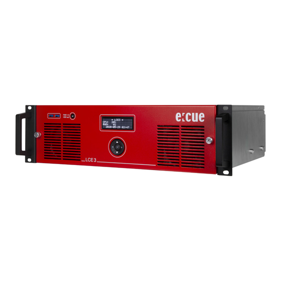
Produktdaten 15.2 Anschlüsse und Schnittstellen Vorderseite LCE 3 2 x USB 3.0 Schnittstellen für USB-Speichermedien Netzschalter und Festplattenaktivitätsanzeige Anzeigefeld für System- und Anwendungsmeldungen Cursor-Steuertasten Lüftereinlässe Rändelmuttern für die Frontplattenmontage Über die USB-Schnittstellen können Medienlaufwerke wie CD / DVD-Treiber oder USB-Speichersticks für Updates oder Datenaustausch angeschlossen werden. -
Seite 59: Rückseite
Produktdaten Rückseite 6 x Potenzialfreie Kontakteingänge und 12 V Gleichstrom Kontaktversorgung 2 x Relaissteuerausgänge; Relais 1 links, Relais 2 rechts Erdungsanschluss Hauptsteckdose, IEC Hauptschalter Hauptplatine (USB, PS/2, Audio etc.) 4 x Mini DisplayPort-Ausgänge LCE3FX Version ausschließlich: Video Capture-Karte, DVI-I Das BIOS und der Boot-Bildschirm sind nur über die Schnittstellen der Hauptplatine zugänglich. -
Seite 60: Potenzialfreie Kontakte
Produktdaten Potenzialfreie Kontakte 1 2 3 4 5 6 12 V DC Out In 1 ... 6 = 12 V Gleichstrom, max. 70 mA 2 ... 7 6 Digitaleingänge (In 1 ... In 6) Masse Verwenden Sie Kabel mit Zwinge und Kunststoffhülse mit einem Leiterquerschnitt von 0,25 mm²... - Seite 61 Produktdaten Relaisschnittstellen Mittlerer Kontakt Äußerer Kontakt, im ausgeschalteten Zustand geschlossen (normalerweise geschlossen) Äußerer Kontakt, im eingeschalteten Zustand geschlossen (normalerweise offen) Die LCE 3 (fx) hat zwei Relaisausgänge der Form C. NC: Normalerweise geschlossen. Wenn es ausgeschaltet ist, bleibt das Relais in diesem Zustand.
- Seite 62 Produktdaten Besondere Hinweise bei Verwendung von Netzspannung oder anderen gefährlichen Spannungen: — Alle Arbeiten dürfen nur von einer qualifizierten Person ausgeführt werden. — Die LCE 3 (fx) muss für alle Verkabelungsarbeiten ausgeschaltet sein. — Die feldseitigen Leitungen zum Anschluss an die Relais müssen bei allen Arbeiten an der LCE 3 (fx) spannungslos (abgeschaltet) sein.
- Seite 63 Produktdaten Besondere Hinweise bei Verwendung von Netzspannung oder anderen gefährlichen Spannungen: — Der mitgelieferte Stecker vom Typ GFKC2,5/3-ST-7,62 (Phoenix Contact 1939646) ist für den Betrieb mit Netzspannung ausgelegt, bietet aber je nach verwendeter Verdrahtung möglicherweise keinen ausreichenden Schutz gegen unbeabsichtigtes Berühren. In diesem Fall muss die Person, die die Arbeiten ausführt, dafür sorgen, dass ein ausreichender Berührungsschutz gewährleistet ist (z.B.
- Seite 64 Produktdaten Besondere Hinweise bei Verwendung von Netzspannung oder anderen gefährlichen Spannungen: — Generell wird empfohlen, bei Verwendung von Netzspannung einen Stecker mit Schutzabdeckung einschließlich Zugentlastung zu verwenden. Dies ermöglicht auch die Verwendung von doppelt isolierten Kabeln. Stecker: GMSTB 2,5/3-ST-7,62 Phoenix-Contact 1767012 Kabelgehäuse: KGG-MSTB 2,5/4 Phoenix-Contact 1715343 Hinweis: Stecker und Kabelgehäuse sind nicht im...
- Seite 65 Produktdaten Besondere Hinweise bei Verwendung von Netzspannung oder anderen gefährlichen Spannungen — Das Gehäuse ist standardmäßig über den Netzstecker geerdet. Bei Verwendung von Netzspannung an der Relaisschnittstelle wird empfohlen, einen zusätzlichen Erdungsdraht zu verwenden und diesen mit dem Erdungsanschluss (6,3 mm Flachstecker) zu verbinden. —...
- Seite 66 Produktdaten Relaisstecker Max. Max. Bedingung Spannung Strom für UL Mitgelieferter Stecker 250 V AC 10 A Beachten Sie die GFKC 2,5/3-ST-7,62 Sicherheits- vorschriften für die Verwendung von Wechselstromnetzen. GMSTB 2,5/3-ST-7,62 250 V AC 10 A Keine zusätzlichen nur in Kombination mit Sicherheits- Kabelgehäuse anforderungen...
-
Seite 67: Schnittstellen Der Hauptplatine
Produktdaten Schnittstellen der Hauptplatine 2 x PS/2 Schnittstellen, oben für Maus, unten für Tastatur 4 x USB 2.0 Schnittstellen, schwarz 2 x DisplayPort 1 x Serielle Schnittstelle, RS-232 Sub-D 1 x Video-Ausgang DVI-D 2 x Ethernet-Schnittstellen, 10/100/1000 MBits/s, RJ45 2 x USB 3.1 Schnittstellen, Gen 2, rot 2 x USB 3.1 Schnittstellen, Gen 1, blau 1 x Kopfhörer / Audio-Eingang 1 x Kopfhörer / Audio-Ausgang... -
Seite 68: Serielle Schnittstelle
Produktdaten Serielle Schnittstelle RS 232 - 9 pin male RxD (Datenempfang) TxD (Datenübertragung) -
Seite 69: Allgemeine Hinweise
Temperatur am Installationsort angenommen hat. Bewahren Sie die Verpackung für einen späteren Transport auf. Überprüfen Sie die Vollständigkeit des Lieferumfanges nach Kapitel “14.2 Lieferumfang” auf Seite 54. Sollten Komponenten beschädigt sein oder fehlen, wenden Sie sich an Ihren OSRAM Support Service. 16.3 Technischer Support Bei technischen Problemen oder Fragen zum Gerät wenden Sie... -
Seite 70: Garantiebestimmungen
Die Garantie- und Gewährleistungsbestimmungen finden sich in der Regel im Angebot und in der Auftragsbestätigung. Zusätzlich sind Informationen dazu auf der OSRAM- Webseite www.osram.de unter “Services” “OSRAM Garantien” aufgeführt. Gesetzlich geregelte Garantiebedingungen sind davon unberührt. -
Seite 71: Montage
Installation Schließen Sie Kabel und Daten nur an, wenn das Gerät ausgeschaltet ist. 17.1 Montage Sie können dieLighting Control Engine 3 (fx) in alle Standard-19- Zoll-Rack-Systeme einbauen. Verwenden Sie die mitgelieferten Rack-Montageschienen und Schrauben, um das Gerät im Rack zu befestigen. -
Seite 72: Stromversorgung
Konfiguration 17.2 Stromversorgung Verwenden Sie das mitgelieferte Netzkabel, um die Versorgungsspannung anzuschließen. Stellen Sie sicher, dass das Netzkabel mit der Klemme an der LCE 3 (fx) befestigt ist. Um das Gerät einzuschalten, schalten Sie den Netzschalter ein. Wenn Geräte zum System hinzugefügt oder entfernt werden, versichern Sie sich, dass die Stromkabel entfernt sind, bevor Signalkabel verbunden werden. -
Seite 73: Setup
Konfiguration Im laufenden Betrieb können Geräte an die USB-Schnittstellen, die Mini DisplayPort-Ausgänge, die Hauptplatinen-Schnittstellen und die Video Capture-Karte hinzugefügt werden. Schalten Sie den Server nicht mit dem Netzschalter oder durch Trennen der Stromversorgung aus, sondern fahren Sie den Server über das Windows Startmenü... -
Seite 74: Netzwerkeinstellungen Lce 3 (Fx)
Konfiguration Stellen Sie beim Setup eine Internetverbindung für die LCE 3 (fx) bereit. Falls notwendig inklusive einem aktivierten DHCP-Server, damit der LCE 3 (fx) eine IP-Adresse zugewiesen wird. Führen Sie für Windows, SYMPHOLIGHT und die LAS Updates durch. Es wird empfohlen, in den Einstellungen Updates zu erlauben und durchzuführen. -
Seite 75: Netzwerkeinstellungen Sympholight
Konfiguration Verwenden Sie den empfohlenen, eigenständigen Netzwerkadressraum 192.168.123.xxx bei einem der Netzwerkadapter. 18.4 Netzwerkeinstellungen SYMPHOLIGHT Die e:cue SYMPHOLIGHT Anwendung ist auf der LCE 3 (fx) vorinstalliert. SYMPHOLIGHT ist eine Software zur Planung, Kontrolle und Programmierung von mittel bis hoch komplexen Lichtinstallationen. - Seite 76 Konfiguration — Klicken Sie im linken oberen Menü und wählen Sie Tools Settings — In dem Dialogfenster klicken Sie Application Settings Network — Geben Sie die IP-Adresse(n) von Ihrem Netzwerk in das Eingabefeld ein oder wählen Sie Interfaces for e:net IP-Adresse(n) aus.
-
Seite 77: Netzwerkeinstellungen Las
Konfiguration das SYMPHOLIGHT User Manual. Ohne einen DHCP-Server darf jeweils nur ein SYMPL Node zur Zeit angeschlossen sein, da sonst identische IP-Adressen zu Konflikten führen und die ordnungsgemäße Kommunikation stören. 18.5 Netzwerkeinstellungen LAS Die e:cue LAS Anwendung ist auf der LCE 3 (fx) vorinstalliert. Die LAS ist eine Software zur Erstellung von Lichtshows und zur Steuerung komplexer Lichtinstallationen sowie zur Kontrolle des Netzwerkes und aller enthaltener Geräte. - Seite 78 Konfiguration — Unter dem -Tab können Sie wählen, über welche Advanced Netzwerkkarte der Programmer e:net-Output sendet. Ebenso können Sie die Einstellungen für die Art-Net- und KiNet- Protokolle setzen. e:cue empfiehlt, nur ein Protokoll pro Netzwerkkarte zu verwenden: — Klicken Sie , um die Änderungen auszuführen.
-
Seite 79: Systemanzeige Lce 3 (Fx)
Systemanzeige LCE 3 (fx) 19 Systemanzeige LCE 3 (fx) Nach dem Einschalten des Systems starten Sie die Lichtsteuerungsanwendung SYMPHOLIGHT oder Lighting Application Suite. Um die Anwendung beim Einschalten automatisch zu starten, konfigurieren Sie die Einstellungen der Anwendung so, dass sie mit Windows startet. Die Systemanzeige durchläuft normalerweise verschiedene Anzeigeseiten. - Seite 80 Systemanzeige LCE 3 (fx) *2019-05-27 12:33 Systemzeit Sunrise: 05:17 Sonnenaufgang einschl. Sommerzeit. Noon: 13:22 Zenit einschl. Sommerzeit. Sunset: 21:36 Sonnenuntergang einschl. Sommerzeit. * LCE 3 (fx) * Systemtyp. CPU: Akt. CPU-Auslastung. RAM: 13% Akt. Speicherauslastung. Fan: OK 11:04 Lüfterstatus und Systemzeit. * LCE 3 (fx) * Systemtyp.
-
Seite 81: Menü "Netzwerk/Anschlüsse
Systemanzeige LCE 3 (fx) * Device Manager * Device Manager-Übersicht. 51 Devices Gesamtzahl Geräte im Programmer. 28 Online Anzahl Geräte im Online-Status. 23 Offline Anzahl Geräte im Offline-Status. * Custom Menu * Drücken der Cursortaste für kundenspezifische Funktionen. Details dazu im LAS System Manual. Auswahl der Funktion mit den Cursortasten und , die OK-Taste startet die Funktion. -
Seite 82: Anzeigeeinstellungen
Systemanzeige LCE 3 (fx) Anzeige-Einstellungen In diesem Menü können Kontrast und Hintergrundbeleuchtung eingestellt werden. mit den Tasten werden die Funktionen ausgewählt, mit die eigentliche Einstellung aufgerufen. * Contrast * Drücken der Cursortaste zum Einstellen des Kontrastes. Setup Press RIGHT *Contrast Value * Mit den Tasten wird der Kontrast justiert. - Seite 83 Systemanzeige LCE 3 (fx) Aktive Treiber Diese Untermenüs zeigen alle über den Device Manager von SYMPHOLIGHT oder des Programmers eingebundenen Geräte und Schnittstellen. Mit den Cursortasten können die Geräte ausgewählt werden. Zurück zum Hauptmenü mit der Taste . Folgend nur einige Beispiele. * LCE 3 (fx) I/O Die LCE 3 (fx) I/O-Schnittstelle (Schaltkontakte Inte...
-
Seite 84: Lce3Fx Videoeingang-Setup
LCE3FX Videoeingang-Setup 20 LCE3FX Videoeingang-Setup Konfigurieren Sie den Videoeingang über die LAS. 21 Fehlerbehebung Problem Zu prüfen Grund Details Das System Ist der Ist der Bedienungs- lässt sich nicht Netzschalter Hauptschalter anleitung einschalten auf der auf AUS, lässt Rückseite auf sich das AUS? System von der... - Seite 85 Fehlerbehebung Schalteingänge Ist das Der Treiber des LAS System funktionieren LCE 3 (fx) I/O- LCE 3 (fx) IO- Manual, nicht System im System muss SYMPHO- Device eingebunden LIGHT Manager des sein. Die System Programmer LCE 3 (fx) Manual aktiviert? muss in Ist die SYMPHO- LCE 3 (fx) im...
- Seite 86 Fehlerbehebung Relaisausgänge Ist das Der Treiber des LAS System funktionieren LCE 3 (fx) I/O- LCE 3 (fx) IO- Manual, nicht System im System muss SYMPHO- Device eingebunden LIGHT Manager des sein. Die System Programmer LCE 3 (fx) Manual aktiviert? muss in Ist die SYMPHO- LCE 3 (fx) im...
- Seite 87 Fehlerbehebung Angeschlosse- e:net- Es gibt Bedienungs- ne Ethernet- Zuweisungen mindestens anleitung systeme werden in den zwei Ethernet- nicht erkannt Application Ports in der Options in LCE 3 (fx). Die SYMPHO- richtige IP- LIGHT / des Adresse muss Programmers in Windows prüfen.
-
Seite 88: Wartung
22 Wartung Versuchen Sie nicht, das Gerät zu reparieren. Schicken Sie es zur Reparatur oder zum Ersatz an Ihren OSRAM Vertriebspartner. Im Betrieb muss die rote Frontplatte befestigt sein (Brandschutz). Die rote Frontplatte darf nur entfernt werden, wenn das Gerät vom Stromnetz getrennt ist. -
Seite 89: Festplatte Wechseln
Wartung sicher, dass kein Wasser in das Gehäuse gelangt. Dieses kann die Elektronik beschädigen. 22.2 Festplatte wechseln Zur Erhöhung der Zuverlässigkeit ist das System mit einem RAID 1 Datenträgerverbund ausgestattet, die SSDs in den Wechselrahmen spiegeln sich gegenseitig. Verwenden Sie die installierte Intel Rapid Storage Technology-Software zur Verwaltung der SSDs. -
Seite 90: Demontage
Rücksendung der LCE 3 (fx) Falls die LCE 3 (fx) zurückgesendet wird, z. B. zum Austausch, berücksichtigen Sie bitte Folgendes: Sorgen Sie für eine regelmäßige Datensicherung, diese liegt in der Verantwortung des Benutzers. OSRAM kann nicht garantieren, dass Benutzerdaten bei der Reparatur erhalten bleiben. -
Seite 91: Zertifizierung
Zertifizierung 24 Zertifizierung e:cue Lighting Control Engine 3 (fx) ist zertifiziert nach EN 55032:2016-02, EN 55035:2018-04, EN 62368:2017-07 Conforms to ANSI/UL Std. 62368-1 Certified to CAN/CSA Std. C22.2 NO. 62368-1 40006876... -
Seite 92: Appendix / Anhang
Appendix / Anhang Appendix / Anhang... - Seite 94 OSRAM GmbH Sales Operations Head office / Zentrale: Karl-Schurz-Str. 38 Marcel-Breuer-Strasse 6 33100 Paderborn, Germany 80807 Munich, Germany +49 5251 54648-0 Phone +49 89 6213-0 support@ecue.com Fax +49 89 6213-2020 www.ecue.com www.osram.com Light is OSRAM Our Brand...