Herunterladen Inhalt Inhalt Diese Seite drucken
HBM S9M Serie Montageanleitung
Vorschau ausblenden Andere Handbücher für S9M Serie:
Inhaltsverzeichnis

Werbung

Verfügbare Sprachen

Verfügbare Sprachen

Mounting Instructions | Montageanleitung |
Notice de montage | Istruzioni per il montaggio
English
Deutsch
Français
Italiano
S9M

Werbung

Inhaltsverzeichnis
loading

Inhaltszusammenfassung für HBM S9M Serie

  • Seite 1 Mounting Instructions | Montageanleitung | Notice de montage | Istruzioni per il montaggio English Deutsch Français Italiano...
  • Seite 2 Tel. +49 6151 803-0 Fax +49 6151 803-9100 info@hbm.com www.hbm.com Mat.: 7-2001.3019 DVS: A03019_05_YI0_04 HBM: public 04.2018 E Hottinger Baldwin Messtechnik GmbH. Subject to modifications. All product descriptions are for general information only. They are not to be understood as a guarantee of quality or durability.
  • Seite 3 Mounting Instructions | Montageanleitung | Notice de montage | Istruzioni per il montaggio English Deutsch Français Italiano...
  • Seite 4: Inhaltsverzeichnis

    ..........A03019_05_YI0_04 HBM: public...
  • Seite 5 ..........A03019_05_YI0_04 HBM: public...
  • Seite 6: Safety Instructions

    The following limits set out in the technical data sheets must not be exceeded: S Limit loads S Lateral load limits and limit bending moments S Breaking loads S Permissible dynamic loads S Temperature limits A03019_05_YI0_04 HBM: public...
  • Seite 7 (safety and accident prevention regulations of the Employers' Liability Insur­ ance Association) when using the force transducers. Force transducers can break, particularly if overloaded. The breakage of a force transducer can also A03019_05_YI0_04 HBM: public...
  • Seite 8 This includes people who meet at least one of the three following requirements: S Knowledge of the safety concepts of automation technology is a require­ ment and as project personnel, you must be familiar with these concepts. A03019_05_YI0_04 HBM: public...
  • Seite 9 The S9M force transducer is maintenance-free. Accident prevention The prevailing accident prevention regulations must be taken into account, even though the nominal (rated) force values in the destructive range are well in excess of the full scale value. A03019_05_YI0_04 HBM: public...
  • Seite 10: Markings Used

    This marking draws your attention to important infor­ mation about the product or about handling the prod­ Important uct. Emphasis Italics are used to emphasize and highlight text and See … identify references to sections, diagrams, or external documents and files. A03019_05_YI0_04 HBM: public...
  • Seite 11: Scope Of Supply And Equipment Variants

    - 6 m (option 06M0) 2. Plugs We can fit one of the following plugs to the S9M on request: - D-SUB connector, 15-pin: a 15-pin plug for connection to numerous amplifier systems, e.g. MGCplus, Scout, MP85, etc. (option F) A03019_05_YI0_04 HBM: public...
  • Seite 12 TEDS (Transducer Electronic Data Sheet) allows you to store the transduc­ er data (characteristic values) in a chip that can be read out by a connected measuring device (with an appropriate amplifier). HBM records the TEDS data before delivery so that no parameterization of the amplifier is nece­...
  • Seite 13: Application Instructions

    Section Specifications (VDI/VDE 2638) on page 24 lists the permissible limits for mechanical, thermal and electrical stress. It is essential to take these limits into account when planning the measuring set-up, during installation and, ulti­ mately, during operation. A03019_05_YI0_04 HBM: public...
  • Seite 14: Structure And Mode Of Operation

    (Fig. 5.1). This procedure offers the SG a high level of protection against environmental influences. In order to retain the protective effect, this plate must not be damaged in any way. Cover plate Fig. 5.1 SG protection A03019_05_YI0_04 HBM: public...
  • Seite 15: Conditions On Site

    Any resulting corrosion could cause the force transducer to fail. In this case, appropriate protective measures must be implemented. Deposits Dust, dirt and other foreign matter must not be allowed to accumulate sufficiently to divert some of the measuring force, thus invalidating the measured value (force shunt). A03019_05_YI0_04 HBM: public...
  • Seite 16 Notice Measurement errors may be the result if dust or dirt is deposited inside the force transducer. The relevant areas are marked by arrows in Fig. 6.1. Fig. 6.1 Deposits at the marked areas must be avoided A03019_05_YI0_04 HBM: public...
  • Seite 17: Mechanical Installation

    S Welding currents must not be allowed to flow over the transducer. If there is a risk that this might happen, you must provide a suitable low-ohm con­ nection to electrically bypass the transducer. HBM provides the highly fle­ xible EEK ground cable for this purpose, for example. It can be screwed on above and below the transducer.
  • Seite 18: Mounting The S9M

    1. Installation and locking with initial stress (recommended mounting variant): - Screw in the threaded connector - Pre-stress transducer to 110% operating load in tensile direction - Hand-tighten the locknut - Unload the transducer A03019_05_YI0_04 HBM: public...
  • Seite 19: Mounting With Direct Bolted Connection

    Mounting with knuckle eyes Knuckle eyes prevent the application of torsional moments on the transducer and also, when two knuckle eyes are used, bending moments, together with lateral and oblique loadings. They are suitable for use with quasi-static loading A03019_05_YI0_04 HBM: public...
  • Seite 20 - Tighten the locknut to the following torques Nominal (rated) Thread on transducer Tightening torque in NVm force in kN 0.5 … 1 2 … 10 M24X2 M24X2 Notice When locking, the tightening torque must not be shunted through the transd­ ucer. A03019_05_YI0_04 HBM: public...
  • Seite 21 Rigid force transfer Fig. 7.2 Mounting with a knuckle eye Nominal Knuckle eye (NVm) (rated) force 0.5 kN 1-U1R/200KG/ZGW 1 kN 1-U1R/200KG/ZGW 2 kN 1-U2A/1T/ZGUW 5 kN 1-U2A/1T/ZGUW 10 kN 1-U2A/1T/ZGUW 20 kN 1-U2A/5T/ZGUW 50 kN 1-U2A/5T/ZGUW A03019_05_YI0_04 HBM: public...
  • Seite 22 Rigid force transfer Fig. 7.3 Installation with two knuckle eyes Nominal Knuckle eye (NVm) (rated) force: 0.5 kN 1-U1R/200KG/ZGW 1 kN 1-U1R/200KG/ZGW 2 kN 1-U2A/1T/ZGUW 5 kN 1-U2A/1T/ZGUW 10 kN 1-U2A/1T/ZGUW 20 kN 1-U2A/5T/ZGUW 50 kN 1-U2A/5T/ZGUW A03019_05_YI0_04 HBM: public...
  • Seite 23: Electrical Connection

    The connection cable shield is connected to the transducer housing. The tr­ ansducers with free cable ends must be fitted with CE­standard plugs and the shielding connected so they cover a wide area. With other connection tech­ A03019_05_YI0_04 HBM: public...
  • Seite 24: Shortening The Cable

    Electrical connection niques, an EMC-proof shield should be applied in the wire area and this shield­ ing should also be connected extensively (also see HBM Greenline Informa­ tion, brochure i1577). Shortening the cable As the transducer connection uses a six-wire configuration, you can shorten the 6-wire transducer cable without affecting the measurement accuracy.
  • Seite 25: Teds Transducer Identification

    IEEE 1451.4 standard. The S9M can be delivered with TEDS, which is then fitted in the transducer housing, connected and supplied with data by HBM before delivery. If the force transducer is or­ dered without calibration, the characteristic values from the manufacturing cer­...
  • Seite 26: Specifications (Vdi/Vde 2638)

    Output resistance 350 ±1.5 Insulation resistance Giga >2 Ω Operating range of the excitation 0.5….12 u,gt voltage Reference excitation voltage Connection 6-wire configuration Temperature Nominal temperature range -10…+70 t,nom Operating temperature range °C -30…+85 Storage temperature range -30…+85 A03019_05_YI0_04 HBM: public...
  • Seite 27 100 hours) Spring element material Stainless steel in accordance with EN 10088-1 Measuring point protection Hermetically welded enclosure Cable 6-wire cable, PVC insulation Cable length 7.6 m (standard), also available: 1.5 m; 3 m and 6 m A03019_05_YI0_04 HBM: public...
  • Seite 28: Versions And Ordering Numbers

    The example above shows an S9M with 10kN capacity, 3 m cable, a fitted plug for the Quantum system, and TEDS. TEDS is only possible when a plug is fitted. TEDS and open ends cannot be combined. A03019_05_YI0_04 HBM: public...
  • Seite 29: Dimensions

    500 N 50.8 25.4 1 kN 50.8 25.4 2 kN 87.3 57.2 28.6 43.7 5 kN 87.3 57.2 28.6 43.7 10 kN 87.3 57.2 28.6 43.7 20 kN 69.8 34.9 M24x2 50 kN 76.2 38.1 36.5 M24x2 A03019_05_YI0_04 HBM: public...
  • Seite 30: 12.2 Mounting Aids

    0.5 … 1 1-U1R/200 0.05 16.5 12 6.5 KG/ZGW 2…10 1-U2A/1T/ ZGUW 20…50 1-U2A/5T/ M24x2 31 ZGUW The specifications for the knuckle eyes recommended by HBM always meet the permissible limits for mechanical stress for the transducer. A03019_05_YI0_04 HBM: public...
  • Seite 31 Mounting Instructions | Montageanleitung Notice de montage | Istruzioni per il montaggio English Deutsch Français Italiano...
  • Seite 32 ..........A03019_05_YI0_04 HBM: public...
  • Seite 33 ..........A03019_05_YI0_04 HBM: public...
  • Seite 34: Sicherheitshinweise

    Beim Einsatz der Kraftaufnehmer sind die Angaben in den technischen Daten­ blättern unbedingt zu beachten. Insbesondere dürfen die jeweils angegebenen Maximalbelastungen keinesfalls überschritten werden. Nicht überschritten werden dürfen die in den technischen Datenblättern angegebenen S Grenzlasten S Grenzquerlasten und Grenzbiegemomente S Bruchlasten S Zulässige dynamische Belastungen A03019_05_YI0_04 HBM: public...
  • Seite 35 Jede Person, die mit Aufstellung, Inbetriebnahme, Betrieb oder Reparatur eines Kraftaufnehmers beauftragt ist, muss die Montageanleitung und insbesondere die sicherheitstechnischen Hinweise gelesen und verstanden haben. Bei nicht bestimmungsgemäßem Gebrauch der Kraftaufnehmer, bei Nichtbeachtung der Montage- und Bedienungs­ A03019_05_YI0_04 HBM: public...
  • Seite 36 örtlichen Behörden oder an den Händler, bei dem Sie das Produkt erworben haben. Umbauten und Veränderungen Der Aufnehmer darf ohne unsere ausdrückliche Zustimmung weder konstruktiv noch sicherheitstechnisch verändert werden. Jede Veränderung schließt eine Haftung unsererseits für daraus resultierende Schäden aus. A03019_05_YI0_04 HBM: public...
  • Seite 37 Daten in Zusammenhang mit den Sicherheitsbestim­ mungen und Vorschriften einzusetzen. Wartung Der Kraftaufnehmer S9M ist wartungsfrei. Unfallverhütung Obwohl die angegebene Nennkraft im Zerstörungsbereich ein Mehrfaches vom Messbereichsendwert beträgt, müssen die einschlägigen Unfallverhütungsvor­ schriften der Berufsgenossenschaften berücksichtigt werden. A03019_05_YI0_04 HBM: public...
  • Seite 38: Verwendete Kennzeichnungen

    Diese Kennzeichnung weist auf wichtige Informa­ tionen zum Produkt oder zur Handhabung des Pro­ Wichtig duktes hin. Hervorhebung Kursive Schrift kennzeichnet Hervorhebungen im Siehe … Text und kennzeichnet Verweise auf Kapitel, Bilder oder externe Dokumente und Dateien. A03019_05_YI0_04 HBM: public...
  • Seite 39: Lieferumfang Und Ausstattungsvarianten

    - 6 m (Option 06M0) 2. Stecker Auf Wunsch montieren wir einen der folgenden Stecker an die S9M: - SUB-D Stecker, 15 polig: 15 poliger Stecker zum Anschluss an viele Messverstärkersysteme, z.B. MGCplus, Scout, MP85 u.v.m. (Option F) A03019_05_YI0_04 HBM: public...
  • Seite 40 Aufnehmerdaten (Kennwerte) in einem Chip zu hinterlegen, der von dem angeschlossenem Messgerät (Entsprechender Messverstärker vorausge­ setzt) ausgelesen wird. HBM beschreibt den TEDS bei Auslieferung, so dass keine Parametrierung des Verstärkers notwendig ist. TEDS können an die S9M nur im Stecker montiert werden, deshalb kann die Ausführung „mit freien Kabelenden“...
  • Seite 41: Anwendungshinweise

    Die Grenzen für die zulässigen mechanischen, thermischen und elektrischen Beanspruchungen sind im Abschnitt Technische Daten (VDI/VDE 2638) auf Seite 25 aufgeführt. Bitte berücksichtigen Sie diese unbedingt bei der Planung der Messanordnung, beim Einbau und letztendlich im Betrieb. A03019_05_YI0_04 HBM: public...
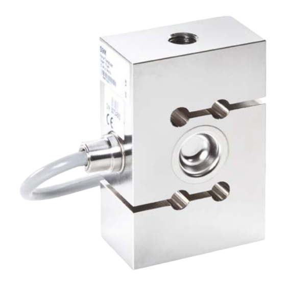
  • Seite 42: Aufbau Und Wirkungsweise

    Zum Schutz der DMS sind die Kraftaufnehmer S9M an entsprechender Stelle mit einem dünnen Blech verschweißt (Abb. 5.1). Dieses Verfahren bietet einen hohen Schutz der DMS gegen Umwelteinflüsse. Um die Schutzwirkung nicht zu gefährden, darf dieses Blech keinesfalls beschädigt werden. Abdeckblech Abb. 5.1 Schutz der DMS A03019_05_YI0_04 HBM: public...
  • Seite 43: Bedingungen Am Einsatzort

    Die dadurch evtl. auftretende Korrosion kann zum Ausfall des Kraftaufnehmers führen. In diesem Fall sind entsprechende Schutzmaßnahmen vorzusehen. Ablagerungen Staub, Schmutz und andere Fremdkörper dürfen sich nicht so ansammeln, dass sie einen Teil der Messkraft umleiten und dadurch den Messwert verfälschen (Kraftnebenschluss). A03019_05_YI0_04 HBM: public...
  • Seite 44 Bedingungen am Einsatzort Hinweis Fehlmessungen können die Folge sein, wenn sich Staub oder Schmutz innerhalb der Kraftaufnehmer ablagern. Die betreffenden Stellen sind in Abb. 6.1 mit Pfeilen markiert. Abb. 6.1 Ablagerungen an den gekennzeichneten Stellen sind zu vermeiden A03019_05_YI0_04 HBM: public...
  • Seite 45: Mechanischer Einbau

    S Es dürfen keine Schweißströme über den Aufnehmer fließen. Sollte diese Gefahr bestehen, so müssen Sie den Aufnehmer mit einer geeigneten niederohmigen Verbindung elektrisch überbrücken. Hierzu bietet z. B. HBM das hochflexible Erdungskabel EEK an, das oberhalb und unterhalb des Aufnehmers angeschraubt wird.
  • Seite 46: Montage Des S9M

    Einbauteile, sowie Zug­/Druckstäbe, Schrauben und Gelenkösen. Montage des S9M 7.3.1 Montage mit Zug-/Druckstäben Bei dieser Montagevariante wird der Aufnehmer mittels Zug-/Druckstäben an ein Konstruktionselement montiert und kann in Zug- und in Druckrichtung messen. Auch Wechsellasten werden korrekt erfasst, wenn der Aufnehmer A03019_05_YI0_04 HBM: public...
  • Seite 47 Gewinde am Aufnehmer Anzugsmoment in NVm 0.5 … 1 2 … 10 M24X2 M24X2 Hinweis Beim Kontern darf das Anzugsmoment keinesfalls durch den Aufnehmer hindurch geleitet werden. Die Montage mittels Vorspannung ist der Montage mit einem definierten Anzugsmoment vorzuziehen. A03019_05_YI0_04 HBM: public...
  • Seite 48: Montage Mit Direkter Verschraubung

    - Kontermutter handfest anziehen - Aufnehmer entlasten 2. Einbau der Gelenkösen und Kontern mittels Drehmoment: - Kontermutter bis zur Öse zurückdrehen - Gelenköse in den Aufnehmer schrauben (zul. Einschraubtiefe beachten) - Gelenköse ausrichten - Kontermutter mit folgenden Drehmomenten anziehen A03019_05_YI0_04 HBM: public...
  • Seite 49 Mechanischer Einbau Nennkraft in kN Gewinde am Aufnehmer Anzugsmoment in NVm 0.5 … 1 2 … 10 M24X2 M24X2 Hinweis Beim Kontern darf das Anzugsmoment keinesfalls durch den Aufnehmer hindurch geleitet werden. A03019_05_YI0_04 HBM: public...
  • Seite 50 Bei der Benutzung einer Gelenköse ergeben sich folgende Einbaumaße: starre Kraftausleitung Abb. 7.2 Einbau mit einer Gelenköse Nennkraft Gelenköse (NVm) 0,5 kN 1-U1R/200KG/ZGW 1 kN 1-U1R/200KG/ZGW 2 kN 1-U2A/1T/ZGUW 5 kN 1-U2A/1T/ZGUW 10 kN 1-U2A/1T/ZGUW 20 kN 1-U2A/5T/ZGUW 50 kN 1-U2A/5T/ZGUW A03019_05_YI0_04 HBM: public...
  • Seite 51 Bei der Benutzung von zwei Gelenkösen ergeben sich folgende Einbaumaße: starre Kraftausleitung Abb. 7.3 Einbau mit zwei Gelenkösen Nennkraft Gelenköse (NVm) 0,5 kN 1-U1R/200KG/ZGW 1 kN 1-U1R/200KG/ZGW 2 kN 1-U2A/1T/ZGUW 5 kN 1-U2A/1T/ZGUW 10 kN 1-U2A/1T/ZGUW 20 kN 1-U2A/5T/ZGUW 50 kN 1-U2A/5T/ZGUW A03019_05_YI0_04 HBM: public...
  • Seite 52: Elektrischer Anschluss

    Ausgangsspannung am Messverstärker positiv. Die Aufnehmer werden standardmäßig mit einem 7,6 m langen Kabel mit freien Enden geliefert. Der Schirm des Anschlusskabels ist mit dem Aufnehmergehäuse verbunden. An Aufnehmer mit freiem Kabelende sind Stecker nach CE­Norm zu A03019_05_YI0_04 HBM: public...
  • Seite 53: Kabelkürzung

    Elektrischer Anschluss montieren, die Schirmung ist dabei flächig aufzulegen. Bei anderen Anschluss­ techniken ist im Litzenbereich eine EMV­feste Abschirmung vorzusehen, bei der ebenfalls die Schirmung flächig aufzulegen ist (siehe auch HBM­Green­ line­Information, Druckschrift i1577). Kabelkürzung Da der Anschluss des Aufnehmers in Sechsleiter-Technik ausgeführt ist, können Sie das 6-adrige Kabel des Aufnehmers kürzen, ohne dass dadurch...
  • Seite 54: Aufnehmer-Identifikation Teds

    TEDS ohne weitere Sensorleitung auszulesen. Wird ein entsprechender Verstärker angeschlossen (z.B. QuantumX von HBM), so liest die Elektronik des Verstärkers den TEDS Chip aus, die Parame­ trierung erfolgt dann automatisch ohne weiteres Zutun des Benutzers. Der Chip-Inhalt kann mit entsprechender Hard- und Software editiert und geändert werden.
  • Seite 55: Technische Daten (Vdi/Vde 2638)

    Relative Abweichung des Nullsignals Kennwertabweichung 0.25 Kennwertunterschied Zug/Druck Eingangswiderstand 389 ±15 Ω Ausgangswiderstand 350 ±1,5 Isolationswiderstand Giga >2 Ω Gebrauchsbereich der Speise­ 0,5….12 u,gt spannung Referenzspeisespannung Anschluss 6-Leiterschaltung Temperatur Nenntemperaturbereich -10…+70 t,nom Gebrauchstemperaturbereich °C -30…+85 Lagertemperaturbereich -30…+85 A03019_05_YI0_04 HBM: public...
  • Seite 56 Schutzart nach EN 60529 IP68 Prüfbedingung 1 m Wassersäule / 100 Stunden Federkörperwerkstoff Rostfreier Stahl nach EN 10088-1 Messstellenschutz Hermetisch verschweißtes Gehäuse Kabel 6-Leiterkabel, PVC-Isolation Kabellänge 7,6 m (Standard), weiterhin bestellbar: 1,5 m; 3 m und 6 m A03019_05_YI0_04 HBM: public...
  • Seite 57: Ausführungen Und Bestellnummern

    Das Beispiel oben zeigt eine S9M mit 10kN Nennkraft, 3 m Kabel, einem mon­ tiertem Stecker für das Quantum-System und TEDS TEDS sind nur bei der Steckermontage möglich, die Kombination offene Enden und TEDS kann nicht angeboten werden. A03019_05_YI0_04 HBM: public...
  • Seite 58: Abmessungen

    500 N 50,8 25,4 1 kN 50,8 25,4 2 kN 87,3 57,2 28,6 43,7 5 kN 87,3 57,2 28,6 43,7 10 kN 87,3 57,2 28,6 43,7 20 kN 69,8 34,9 M24x2 50 kN 76,2 38,1 36,5 M24x2 A03019_05_YI0_04 HBM: public...
  • Seite 59: 12.2 Einbauhilfen

    Gelenköse Gewicht kraft (kN) (kg) 0,5 … 1 1-U1R/200 0,05 16,5 12 6,5 KG/ZGW 2…10 1-U2A/1T/ ZGUW 20…50 1-U2A/5T/ M24x2 31 ZGUW Die technischen Daten der von HBM empfohlenen Gelenkösen erfüllen stets die zulässige mechanische Beanspruchung des Aufnehmers. A03019_05_YI0_04 HBM: public...
  • Seite 60 Abmessungen A03019_05_YI0_04 HBM: public...
  • Seite 61 Mounting Instructions | Montageanleitung | Notice de montage | Istruzioni per il montaggio English Deutsch Français Italiano...
  • Seite 62 ..........A03019_05_YI0_04 HBM: public...
  • Seite 63 Accessoires de montage ........A03019_05_YI0_04 HBM: public...
  • Seite 64: Consignes De Sécurité

    être dépassées. Il ne faut pas dépasser les valeurs indiquées dans les caractéristiques techniques pour : S les charges limites, S les charges transverses limites et moments de flexion limites S les charges de rupture, S les charges dynamiques admissibles, A03019_05_YI0_04 HBM: public...
  • Seite 65 à la sécurité. En A03019_05_YI0_04 HBM: public...
  • Seite 66 Il est interdit de modifier le capteur sur le plan conceptuel ou celui de la sécu­ rité sans accord explicite de notre part. Nous ne pourrons en aucun cas être tenus responsables des dommages qui résulteraient d'une modification quel­ conque. A03019_05_YI0_04 HBM: public...
  • Seite 67 Bien que la force nominale indiquée dans la plage de destruction corresponde à un multiple de la pleine échelle, il est impératif de respecter les directives pour la prévention des accidents du travail éditées par les caisses profession­ nelles d'assurance accident. A03019_05_YI0_04 HBM: public...
  • Seite 68: Marquages Utilisés

    Important sont fournies. Mise en valeur Les caractères en italique mettent le texte en valeur Voir … et signalent des renvois à des chapitres, des illus­ trations ou des documents et fichiers externes. A03019_05_YI0_04 HBM: public...
  • Seite 69: Étendue De La Livraison Et Variantes D'équipement

    Vous pouvez également commander ce capteur de force avec les lon­ gueurs de câbles suivantes : - 1,5 m (option 01M5) - 3 m (option 03M0) - 6 m (option 06M0) 4. Connecteur Sur demande, nous montons l'un des connecteurs suivants sur le S9M : A03019_05_YI0_04 HBM: public...
  • Seite 70 (à condition de disposer de l'amplificateur de mesure adéquat). HBM inscrit les données sur la fiche TEDS à la livraison, de sorte qu'aucun paramétrage de l'amplificateur ne soit nécessaire. La technologie TEDS ne peut être installée sur les S9M que dans le connecteur mâle.
  • Seite 71: Conseils D'utilisation

    Les limites des sollicitations mécaniques, thermiques et électriques autorisées sont disponibles au chapitre Caractéristiques techniques (VDI/VDE 2638), page 24. Veuillez impérativement en tenir compte lors de la conception de l'agencement de mesure, lors du montage et en fonctionnement. A03019_05_YI0_04 HBM: public...
  • Seite 72: Structure Et Principe De Fonctionnement

    à une fine plaque à l'endroit adéquat (Fig. 5.1). Ce procédé offre une grande protection des jauges contre les influences ambiantes. Pour ne pas porter atteinte à l'effet de cette protection, la plaque ne doit en aucun cas être endommagée. Plaque de protection Fig. 5.1 Protection des jauges A03019_05_YI0_04 HBM: public...
  • Seite 73: Conditions Sur Site

    Dans ce cas, il faut prévoir des mesures de protection appropriées. Dépôts La poussière, la saleté et autres corps étrangers ne doivent pas s'accumuler de manière à dévier une partie de la force de mesure et ainsi à fausser la valeur de mesure (shunt). A03019_05_YI0_04 HBM: public...
  • Seite 74 Des erreurs de mesure peuvent se produire lorsque de la poussière ou des saletés se déposent à l'intérieur des capteurs de force. Les zones concernées sont repérées par des flèches sur la Fig. 6.1. Fig. 6.1 Éviter les dépôts aux endroits signalés A03019_05_YI0_04 HBM: public...
  • Seite 75: Montage Mécanique

    S Aucun courant de soudage ne doit traverser le capteur. Si cela risque de se produire, le capteur doit être shunté électriquement à l'aide d'une liaison de basse impédance appropriée. À cet effet, HBM propose par ex. le câble de mise à la terre très souple EEK vissé au-dessus et au-dessous du capteur.
  • Seite 76: Montage Du S9M

    1. Montage avec précontrainte et blocage par contre-écrou (variante de mon­ tage recommandée) : - Visser le raccord fileté. - Précontraindre le capteur dans le sens de traction à 110 % de la charge de fonctionnement. - Serrer à fond à la main le contre-écrou. A03019_05_YI0_04 HBM: public...
  • Seite 77: Montage Avec Raccord À Vis Direct

    L'emploi d'anneaux à rotule permet d'éviter que des moments de torsion et, en cas d'utilisation de deux anneaux à rotule, des moments de flexion ainsi que des charges transverses et obliques ne pénètrent dans le capteur. Les A03019_05_YI0_04 HBM: public...
  • Seite 78 Force nominale en kN Filetage sur le capteur Couple de serrage en NVm 0,5 … 1 2 … 10 M24X2 M24X2 Note Lors du blocage par contre-écrou, le couple de serrage ne doit en aucun cas traverser le capteur. A03019_05_YI0_04 HBM: public...
  • Seite 79 Transfert de force rigide Fig. 7.2 Montage avec un anneau à rotule Force nom. Anneau à rotule (NVm) 0,5 kN 1-U1R/200KG/ZGW 1 kN 1-U1R/200KG/ZGW 2 kN 1-U2A/1T/ZGUW 5 kN 1-U2A/1T/ZGUW 10 kN 1-U2A/1T/ZGUW 20 kN 1-U2A/5T/ZGUW 50 kN 1-U2A/5T/ZGUW A03019_05_YI0_04 HBM: public...
  • Seite 80 Transfert de force rigide Fig. 7.3 Montage avec deux anneaux à rotule Force nom. Anneau à rotule (NVm) 0,5 kN 1-U1R/200KG/ZGW 1 kN 1-U1R/200KG/ZGW 2 kN 1-U2A/1T/ZGUW 5 kN 1-U2A/1T/ZGUW 10 kN 1-U2A/1T/ZGUW 20 kN 1-U2A/5T/ZGUW 50 kN 1-U2A/5T/ZGUW A03019_05_YI0_04 HBM: public...
  • Seite 81: Raccordement Électrique

    à la norme CE sur les capteurs ayant un câble à extrémités libres. Le blindage doit alors être posé en nappe. Pour les autres techniques de raccordement, il faut prévoir un blindage conforme A03019_05_YI0_04 HBM: public...
  • Seite 82: Raccourcissement De Câble

    Raccordement électrique CEM dans la zone des fils torsadés, celui-ci devant également être posé en nappe (voir aussi les informations Greenline de HBM, brochure i1577). Raccourcissement de câble Comme le capteur est raccordé en technique six fils, il est possible de rac­...
  • Seite 83: Identification Du Capteur (Teds)

    1451.4. Le S9M peut être livré avec fiche TEDS. Cette dernière est alors installée et raccordée dans le boîtier du capteur et les données sont inscrites sur la puce par HBM avant la livraison. Si le capteur de force est commandé sans étalonnage, les valeurs caractéristiques du protocole d'essai sont ins­...
  • Seite 84: Caractéristiques Techniques (Vdi/Vde 2638)

    Ω Plage utile de la tension d'alimen­ 0,5….12 u,gt tation Tension d'alimentation de référence Raccordement Technique 6 fils Température Plage nominale de température -10…+70 t,nom Plage d'utilisation en température °C -30…+85 Plage de température de stockage -30…+85 A03019_05_YI0_04 HBM: public...
  • Seite 85 Matériau du corps d'épreuve Acier inoxydable selon EN 10088-1 Protection du point de mesure Boîtier soudé hermétiquement Câble Câble 6 conducteurs, isolation PVC Longueur de câble 7,6 m (standard), toujours disponibles : 1,5 m, 3 m et 6 m A03019_05_YI0_04 HBM: public...
  • Seite 86: Versions Et Numéros De Commande

    L'exemple ci-dessus montre un S9M d'une force nominale de 10 kN, avec un câble de 3 m, un connecteur mâle monté pour le système Quantum et avec TEDS. La technologie TEDS n'est possible que pour un montage avec connec­ teur : la combinaison extrémités libres-TEDS n'est pas proposée. A03019_05_YI0_04 HBM: public...
  • Seite 87: Dimensions

    500 N 50,8 25,4 1 kN 50,8 25,4 2 kN 87,3 57,2 28,6 43,7 5 kN 87,3 57,2 28,6 43,7 10 kN 87,3 57,2 28,6 43,7 20 kN 69,8 34,9 M24x2 50 kN 76,2 38,1 36,5 M24x2 A03019_05_YI0_04 HBM: public...
  • Seite 88: 12.2 Accessoires De Montage

    0,5 … 1 1-U1R/200 0,05 16,5 12 6,5 KG/ZGW 2…10 1-U2A/1T/ ZGUW 20…50 1-U2A/5T/ M24x2 31 ZGUW Les caractéristiques techniques des anneaux à rotule recommandés par HBM sont toujours conformes à la sollicitation mécanique admissible du capteur. A03019_05_YI0_04 HBM: public...
  • Seite 89 Mounting Instructions | Montageanleitung | Notice de montage | Istruzioni per il montaggio English Deutsch Français Italiano...
  • Seite 90 ......... A03019_05_YI0_04 HBM: public...
  • Seite 91 ........A03019_05_YI0_04 HBM: public...
  • Seite 92: Note Sulla Sicurezza

    Non superare assolutamente i seguenti valori mas­ simi specificati nei prospetti dati: S carichi limite, S carichi laterali limite e momenti flettenti limite S carichi di rottura, S carichi dinamici ammessi, S limiti di temperatura, A03019_05_YI0_04 HBM: public...
  • Seite 93 (norme anti infortuni in vigore) durante il loro maneggio, è possibile che essi vengano danneggiati o distrutti. Specialmente i sovraccarichi possono A03019_05_YI0_04 HBM: public...
  • Seite 94 Per personale qualificato s'intendono coloro che abbiano familiarità con l'instal­ ’ lazione, il montaggio, la messa in funzione e l impiego del prodotto e che per la loro attività abbiano conseguito la corrispondente qualifica. Ciò comprende il personale che soddisfi almeno uno dei tre seguenti requisiti: A03019_05_YI0_04 HBM: public...
  • Seite 95 Manutenzione Il trasduttore di forza S9M on richiede manutenzione. Prevenzione degli infortuni Nonostante il carico di rottura indicato sia un multiplo della forza nominale, si devono osservare le pertinenti prescrizioni antinfortunistiche emanate dalle associazioni di categoria. A03019_05_YI0_04 HBM: public...
  • Seite 96: Simboli Utilizzati

    Questo simbolo segnala informazioni importanti sul prodotto o sul suo maneggio. Importante Evidenziazione Il corsivo evidenzia il testo rimandando a capitoli, Vedere … paragrafi, figure oppure a documenti e file esterni. A03019_05_YI0_04 HBM: public...
  • Seite 97: Dotazione Di Fornitura E Varianti Costruttive

    Su richiesta, sul cavo del trasduttore S9M si possono montare le seguenti spine: - Spina Sub-D a 15 poli: spina a 15 poli per il collegamento ai corrispondenti sistemi di amplificatori, p.es. MGCplus, Scout, MP85, ed altri similari (opzione F) A03019_05_YI0_04 HBM: public...
  • Seite 98 Dati Elettronico Trasduttore) consente di salvare i valori caratteristici del sensore in un Chip leggibile dallo strumento di misura collegato (amplifi­ catore a ciò predisposto). La HBM fornisce il trasduttore con i dati già scritti nel TEDS, per cui non è più necessaria la parametrizzazione dell'amplifica­...
  • Seite 99: Note Sull'impiego

    I limiti ammessi delle sollecitazioni meccaniche, termiche ed elettriche sono indicati nel paragrafo Dati Tecnici (VDI/VDE 2638) a pagina 25 . È essenziale tener conto di questi limiti durante la pianificazione della misura, l'installazione e, infine, durante l'esercizio. A03019_05_YI0_04 HBM: public...
  • Seite 100: Struttura E Modo Operativo

    ER (Fig. 5.1). Questo metodo fornisce un'elevata protezione degli ER dalle influenze ambientali. Per non compromettere l'azione di prote­ zione, questa lamina non deve essere rimossa o danneggiata. Lamina di protezione Fig. 5.1 Protezione degli ER A03019_05_YI0_04 HBM: public...
  • Seite 101: Condizioni Nel Luogo Di Installazione

    Sedimenti Polvere, sporcizia ed altri corpi estranei non si devono accumulare sul trasduttore, poiché potrebbero creare derivazioni della forza e falsare così il valore di misura (shunt di forza). A03019_05_YI0_04 HBM: public...
  • Seite 102 I depositi di polvere o sporcizia sui trasduttori di forza possono provocare errori di misura. Le zone più soggette a tali accumuli sono indicate dalle frecce nella Fig. 6.1 . Fig. 6.1 Impedire l'accumulo di sporcizia e sedimenti nelle zone indicate A03019_05_YI0_04 HBM: public...
  • Seite 103: Montaggio Meccanico

    Esistendo tale pericolo, si deve cavallottare il trasduttore con un idoneo conduttore a bassa resistenza elettrica. A tal scopo usare ad esempio la flessibile trecciola di terra EEK della HBM, fissandola sopra e sotto il tras­ duttore. S Assicurarsi che il trasduttore non possa venir sovraccaricato.
  • Seite 104: Montaggio Del Trasduttore S9M

    1. Montaggio e bloccaggio con precarico (variante di montaggio consigliata): - avvitare le barre negli attacchi filettati, - precaricare in trazione il trasduttore al 110 % del carico operativo, - serrare a mano il controdado di bloccaggio, - scaricare nuovamente il trasduttore. A03019_05_YI0_04 HBM: public...
  • Seite 105: Montaggio Con Avvitamento Diretto

    I golfari snodati impediscono l'introduzione di momenti torcenti e - usandone due - anche di momenti flettenti e di carichi laterali­ ed obliqui nel trasduttore. I golfari snodati sono adatti per carichi statici e quasi statici (carico alternato A03019_05_YI0_04 HBM: public...
  • Seite 106 - serrare il controdado con le seguenti coppie: Forza nominale in Filettatura del trasduttore Coppia di serraggio in NVm 0,5 … 1 2 … 10 M24X2 M24X2 Avviso Serrando i controdadi, evitare assolutamente di esercitare momenti torcenti sul trasduttore. A03019_05_YI0_04 HBM: public...
  • Seite 107 Utilizzando un golfare si hanno le seguenti dimensioni d'ingombro: Introduzione rigida della forza Fig. 7.2 Montaggio di un golfare Forza Golfare snodato (NVm) nominale 0,5 kN 1-U1R/200KG/ZGW 1 kN 1-U1R/200KG/ZGW 2 kN 1-U2A/1T/ZGUW 5 kN 1-U2A/1T/ZGUW 10 kN 1-U2A/1T/ZGUW 20 kN 1-U2A/5T/ZGUW 50 kN 1-U2A/5T/ZGUW A03019_05_YI0_04 HBM: public...
  • Seite 108 Utilizzando due golfari si hanno le seguenti dimensioni d'ingombro: Introduzione rigida della forza Fig. 7.3 Montaggio di due golfari Forza nominale Golfare snodato (NVm) 0,5 kN 1-U1R/200KG/ZGW 1 kN 1-U1R/200KG/ZGW 2 kN 1-U2A/1T/ZGUW 5 kN 1-U2A/1T/ZGUW 10 kN 1-U2A/1T/ZGUW 20 kN 1-U2A/5T/ZGUW 50 kN 1-U2A/5T/ZGUW A03019_05_YI0_04 HBM: public...
  • Seite 109: Collegamenti Elettrici

    Di serie, il trasduttore viene fornito con cavo di collegamento lungo 7,6 m ed estremità libera. La calza (schermo) del cavo è collegata alla custodia del trasduttore. All'estre­ mità libera del cavo si possono montare spine secondo la norma CE e lo A03019_05_YI0_04 HBM: public...
  • Seite 110: Accorciamento Del Cavo

    Collegamenti elettrici schermo deve essere saldato in modo avvolgente. Anche con altre tecniche di connessione si dovrebbe attuare una schermatura EMC fissa parimenti avvol­ gente nella zona di giunzione dei fili (vedere anche l'Informativa HBM­Green­ line, Pubblicazione i1577). Accorciamento del cavo Poiché...
  • Seite 111 Collegamenti elettrici Per garantire la migliore protezione EMC, il trasduttore, il cavo di collegamento e la susseguente elettronica dovrebbero essere posti in un involucro scher­ mato (gabbia di Faraday). A03019_05_YI0_04 HBM: public...
  • Seite 112: Identificazione Trasduttore Teds

    Chip secondo la norma IEEE 1451.4. Il trasduttore S9M può essere fornito con TEDS mon­ tato e collegato nella custodia della spina e iscritto dalla HBM prima della spe­ dizione. Ordinando i trasduttori di forza con TEDS, le specifiche tecniche del protocollo di prova sono memorizzate nel Chip di TEDS.
  • Seite 113 389 ± 15 Ω Resistenza di uscita 350 ± 1,5 Resistenza di isolamento Giga >2 Ω Campo operativo della ten­ 0,5 … 12 u,gt sione di alimentazione Tensione di alimentazione di riferimento Connessione circuito a 6 fili A03019_05_YI0_04 HBM: public...
  • Seite 114: Dati Tecnici (Vdi/Vde 2638)

    Materiale del corpo elastico Acciaio inossidabile secondo EN 10088-1 Protezione del punto di misura Custodia saldata ermeticamente Cavo cavo a 6 fili, isolamento PVC Lunghezza del cavo 7,6 m (standard), lunghezze ordinabili: 1,5 m; 3 m e 6 m A03019_05_YI0_04 HBM: public...
  • Seite 115: Versioni E Numeri Di Ordinazione (No. Cat.)

    L'esempio soprastante mostra un S9M con forza nominale 10 kN, cavo lungo 3 m, spina montata adatta al sistema QuantumX e TEDS. TEDS è possibile solo con spina montata, la combinazione di TEDS con cavo ad estremità libera non può essere offerta. A03019_05_YI0_04 HBM: public...
  • Seite 116: Dimensioni

    500 N 50,8 25,4 1 kN 50,8 25,4 2 kN 87,3 57,2 28,6 43,7 5 kN 87,3 57,2 28,6 43,7 10 kN 87,3 57,2 28,6 43,7 20 kN 69,8 34,9 M24x2 50 kN 76,2 38,1 36,5 M24x2 A03019_05_YI0_04 HBM: public...
  • Seite 117: 12.2 Accessori Di Montaggio

    0,5 … 1 1-U1R/200 0,05 16,5 12 6,5 KG/ZGW 2…10 1-U2A/1T/ ZGUW 20…50 1-U2A/5T/ M24x2 31 ZGUW I dati tecnici dei golfari snodati consigliati dalla HBM soddisfano comple­ tamente i limiti di sollecitazione meccanica ammessi per il trasduttore. A03019_05_YI0_04 HBM: public...
  • Seite 118 HBM Test and Measurement Tel. +49 6151 803-0 Fax +49 6151 803-9100 info@hbm.com measure and predict with confidence...

Diese Anleitung auch für:

S9m 500 nS9m 2 knS9m 20 kn

Inhaltsverzeichnis