Christopeit AF1 Montageanleitung
Inhaltsverzeichnis
Verfügbare Sprachen
Verfügbare Sprachen
Quicklinks
Montage- und Bedienungsanleitung für
Montage- en bedieningshandleiding voor
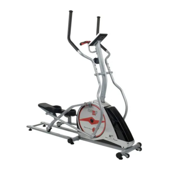
Heimsport-Trainingsgerät
AF 1
D
Bestell-Nr. 1129
NL
Bestellnummer 1129
Инструкция по монтажу и эксплуатации
№ заказа 1129
GB
Assembly and exercise instructions for
Order No. 1129
F
Notice de montage et d'utilisation du
No. de commande 1129
RU
1
Kapitel
Inhaltsverzeichnis

Verwandte Anleitungen für Christopeit AF1


Inhaltszusammenfassung für Christopeit AF1
- Seite 1 Heimsport-Trainingsgerät AF 1 Montage- und Bedienungsanleitung für Assembly and exercise instructions for Bestell-Nr. 1129 Order No. 1129 Montage- en bedieningshandleiding voor Notice de montage et d’utilisation du Bestellnummer 1129 No. de commande 1129 Инструкция по монтажу и эксплуатации № заказа 1129...
-
Seite 2: Inhaltsverzeichnis
Inhaltsübersicht Contents Page 1. Wichtige Empfehlungen und Sicherheitshinweise Seite 2. Einzelteileübersicht Seite 3. Stückliste Seite 4. Montageanleitung mit Explosionsdarstellungen Seite - 10 Sommaire Page 5. Computeranleitung Seite 11 - 12 6. Trainingsanleitung Seite 12 7. Garantiebestimmungen Seite 12 Sehr geehrte Kundin, sehr geehrter Kunde Inhoudsopgave Pagina 31 Wir gratulieren Ihnen zum Kauf dieses Heimsport-Trainingsgerätes und... -
Seite 5: Stückliste
• Großer LCD Computer mit digitaler Anzeige von: Zeit, Geschwindigkeit, Entfernung, Temperatur, ca. Kalorienverbrauch, Pulsfrequenz, Körperfett- Telefax: +49 (0) 20 51 - 6 06 74 4 Analyse und SCAN. e-mail: info@christopeit-sport.com • Eingabe von Grenzwerten wie Zeit, Entfernung und ca. Kalorienverbrauch Überschreitung der Grenzwerte wird angezeigt. www.christopeit-sport.com Geeignet bis zu einem Körpergewicht von max. - Seite 6 Abbildungs- Bezeichnung Abmessung Menge Montiert an ET-Nummer Stück Abbildungs Nr. Endstopfen 36-1129-20-BT Pulsgriffüberzug 36-1129-21-BT Pulskabel 36-1129-22-BT Schwungmasse 33-1129-14-SI Kugellager 6001 36-9718-29-BT Sicherungsring 36-9805-32-BT Unterlegscheibe 10//22 36-9516-57-BT Unterlegscheibe 10//20 36-9518-58-BT Schwungradachse 36-1129-23-BT Achsmutter schmal 3/8“x7 36-9718-41-BT Magnetbügel 33-1129-15-SI Sechskantschraube M8x25 39-10455 Unterlegscheibe M8/22 39-9844-CR...
-
Seite 7: Montageanleitung Mit Explosionsdarstellungen
Montageanleitung Entnehmen Sie alle Einzelteile der Verpackung, legen diese auf den Boden und kontrollieren die Vollzähligkeit grob anhand der Monta- geschritte. Zu beachten ist dabei, dass einige Teile direkt mit dem Grundgestell verbunden sind und vormontiert wurden. Des Weiteren sind auch einige andere Einzelteile schon zu Einheiten zusammengefügt worden. - Seite 8 Schritt 3: Montage des Stützrohres (15) am Grundrahmen (1). Stecker des Computerkabelstranges (41) mit dem aus dem Grundge- stell (1) ragenden Stecker des Sensorkabels (40). (Achtung! Das oben aus dem Stützrohr (15) ragende Ende des Verbindungskabels (41) darf nicht in das Rohr rutschen, da es zur weiteren Montage noch benötigt wird.) Führen Sie das Ende der Widerstandseinstellung (42) zur Seilzugauf- nahme (39) und verbinden Sie diese miteinander wie im Bild A1- A3...
- Seite 9 Schritt 6: Montage der Handgriffe (17+18) an den Verbindungsrohren (21+27). Die Handgriffe (17+18) auf die Verbindungsrohre (21+27) stecken und die Bohrungen in den Rohren so ausrichten, dass sie übereinander liegen. (Achtung! Die Griffrohre müssen nach der Montage so ausgerichtet sein, dass die oberen Enden nach außen (vom Stützrohr (15) weg) gebogen sind.) Die Schrauben (25) mit einem Federring (5) und einer Unterlegscheibe...
-
Seite 10: Benutzung Des Gerätes
Schritt 8: Montage des Pulsgriffes (50) am Stützrohr (15). Nehmen Sie den Computer (43) und stecken Sie das Verbindungska- bel (41) und das Pulskabel (53) in die entsprechenden Buchsen auf Rückseite des Computers (43) ein. Schieben Sie den Computer (43) auf die Computeraufnahme oben am Stützrohr (15) auf und befestigen Sie diesen mittels der Schrauben (93) (Bitte Achten Sie darauf, dass die Kabel beim Aufschieben des Computers nicht eingeklemmt werden.) -
Seite 11: Computeranleitung
Computeranleitung Der mitgelieferte Computer bietet den größten Trainingskomfort. Jeder trai- ningsrelevante Wert wird in einem entsprechenden Sichtfenster angezeigt. Vom Trainingsbeginn an werden die benötigte Zeit, die aktuelle Geschwindigkeit,der ungefähre Kalorienverbrauch, zurückgelegte Entfer- nung Pedalumdrehungen pro Minute (RPM) und der aktuelle Puls angezeigt. Alle Werte werden von Null an aufwärts zählend festgehalten. -
Seite 12: Trainingsanleitung
Weitere Informationen zum Thema Aufwärmübungen, Dehnungsübungen folgenden Faktoren beachtet werden: oder allgemeine Gymnastikübungen finden Sie in unserem Downloadbereich 1. Intensität: unter www.christopeit-sport.com Die Stufe der körperlichen Belastung beim Training muß den Punkt der 4. Motivation normalen Belastung überschreiten, ohne dabei den Punkt der Atemlosigkeit Der Schlüssel für ein erfolgreiches Programm ist ein regelmäßiges Training.