Sony HKDV-900 Bedienungsanleitung
Inhaltsverzeichnis
Verfügbare Sprachen
Verfügbare Sprachen
Quicklinks
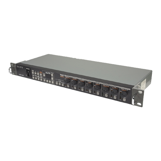
HD DIGITAL VIDEO CONTROLLER
HKDV-900
電気製品は、安全のための注意事項を守らないと、火災
や人身事故になることがあります。
このオペレーションマニュアルには、事故を防ぐための重要な注意事項と製
品の取り扱いかたを示してあります。このオペレーションマニュアルをよく
お読みのうえ、製品を安全にお使いください。お読みになったあとは、いつ
でも見られるところに必ず保管してください。
OPERATION MANUAL
1st Edition (Revised 4)
Serial No. 11001 and Higher (SYL)
[Japanese/English/French/German]
Kapitel
Inhaltsverzeichnis

Verwandte Anleitungen für Sony HKDV-900


Inhaltszusammenfassung für Sony HKDV-900
- Seite 52 • EN55103-2: Elektromagnetische Verträglichkeit (Störfestigkeit) Für die folgenden elektromagnetischen Umgebungen: E4 (kontrollierter EMV-Bereich, z.B. Fernsehstudio). Der Hersteller dieses Produkts ist Sony Corporation, 1-7-1 Konan, Minato-ku, Tokyo, Japan. Der autorisierte Repräsentant für EMV und Produktsicherheit ist Sony Deutschland GmbH, Hedelfinger Strasse 61, 70327 Stuttgart, Deutschland.
- Seite 53 Inhaltsverzeichnis Übersicht ................... 2(DE) Bezeichnung und Funktion der Teile ..........3(DE) Frontplatte ..................3(DE) Rückseite ..................7(DE) Ausgangssignaleinstellung ............... 8(DE) Einstellung für Bildverbesserung ............ 9(DE) Anzeige der Einstellwerte (DIP-Schalter S100-2 auf ON) ..11(DE) Abspeicherung und Aufruf von Parameter- und Systemeinstellungen ..............
-
Seite 54: Übersicht
Die an den Digitalvideorecorder HDW-500/F500/ des HDTV-Bilds beim Randbeschneiden und 2000/M2000/A2100/M2100 HD (hohe Definition) Vertikalposition beim Beschneiden in der anzuschließende HKDV-900 steuert die HD/SD- Betriebsart Letter Box mit einem Aufwärts- Ausgangsvideosignale (High Definition/Standard) Umsetzer. und den Bildverstärker des in den Videorecorder DETAIL GAIN: Schärfe der Randverbesserung... -
Seite 55: Bezeichnung Und Funktion Der Teile
Bezeichnung und Funktion der Teile Frontplatte Bereich für Ausgangssignalwahl Speicherbereich Pegeleinstellbereich HKDV-900 Bereich für Videosteuerwahl Alle Tasten außer STORE, LOAD, CANCEL sowie –/+ im Speicherbereich-Bedienfeld werden bei jedem Drücken aktiviert kder deaktiviert. 3 CONTROL SELECT-Taste 3 Bereich für Videosteuerwahl Wahl des Geräts, das mit dem Anschluß REMOTE OUT (TO VTR) 3 verbunden ist. - Seite 56 Tasten drücken, erscheint der Inhalt 3 LOAD-Taste der INPUT FORMAT-Anzeige an der HKPF-9000 4 CANCEL-Taste auch auf dem MEMORY ADDR.-Display an der HKDV-900. Die blinkenden Tasten haben die folgenden Bedeutungen: 5 –/+-Tasten Blinkende INPUT-Taste: Das Eingangssignal für 6 INPUT/OUTPUT-Tasten HKPF-9000 ist unzulässig.
-
Seite 57: Pegeleinstellbereich
Pegeleinstellbereich Im Pegeleinstellbereich können Sie das am Bereich für Ausgangssignalwahl gewählte Ausgangssignal parametermäßig ändern. Bei Wahl von IMAGE ENHANCER im Bereich für Ausgangssignalwahl lassen sich die Parameter für die Bildverbesserung beeinflussen. 1 HD-SD•SD-HD-Umsetzungsmodus-Wahltasten 2 MASTER/MASTER/–/H CROP•V LETTER-Einstellregler und UNITY-Taste 3 Y/Y/VIDEO/DETAIL GAIN-Einstellregler und UNITY-Taste /B–Y/CHROMA/LIMITER-Einstellregler und UNITY-Taste /R–Y/HUE/CRISP-Einstellregler und UNITY-Taste 6 SETUP/–/SETUP/DEPEND-Einstellregler und UNITY-... - Seite 58 Bezeichnung und Funktion der Teile Bei Wahl von D2: Einstellung der Chroma- 2 MASTER/MASTER/–/H (horizontal) CROP•V Verstärkung (vertikal) LETTER-Einstellregler und UNITY- Bei Wahl von IMAGE ENHANCER: Taste Maximalpegel des zusätzlichen Details zur Nehmen Sie die nachstehend aufgeführten Verbesserung des ursprünglichen Signals Einstellungen gemäß...
-
Seite 59: Rückseite
8 FINE/FINE/H/V RATIO-Einstellregler und 9 –/CROSS COLOR/GAMMA-Einstellregler und PRESET-Taste PRESET-Taste Nehmen Sie die nachstehend aufgeführten Nehmen Sie die nachstehend aufgeführten Einstellungen gemäß dem jeweils gewählten Einstellungen gemäß dem jeweils gewählten Ausgangssignal vor. Durch Drücken der PRESET- Ausgangssignal vor. Durch Drücken der PRESET- Taste wird auf den Mindestwert zurückgeschaltet Taste wird auf den Mittenwert zurückgeschaltet (werkseitige Einstellung), wobei die „MIN“-Anzeige... -
Seite 60: Ausgangssignaleinstellung
LEVEL –∞ bis +3 dB (–3 bis +3 dB)∗ 0 dB SET UP –10 bis +10 % HKDV-900 SYNC PHASE –1.4 bis +1.4 H FINE (SYNC PHASE) ±118 ns (Schritt von 13,5 ns) 0 H ∗ Umschaltung mit dem VIDEO-Verstärkungsschalter Bei Aufleuchten der D1-Taste Drücken Sie eine der Tasten HD, D1 und D2 am... -
Seite 61: Einstellung Für Bildverbesserung
1 2 3 4 5 6 7 8 9 0 1 2 3 4 Das HDTV-Bild (Bildseitenverhältnis 16:9) wird horizontal komprimiert, damit es in das SDTV-Bild (Bildseitenverhältnis 4:3) hineinpaßt. HKDV-900 Aufwärtsumsetzer (SD-HD-Umsetzung) • Randbeschneidungsmodus (CROP-Taste) 1 2 3 4 5 6 7 8 9 0 1 2 3... - Seite 62 Einstellung für Bildverbesserung Nehmen Sie die Einstellungen für Parametereinstellbereiche Bildverbesserung vor. H CROP•V LETTER-Einstellregler Bei Aufleuchten der IMAGE EHANCER-Taste Stellen Sie die Horizontalposition beim Einstellregler Parametereinstellbereich UNITY (PRESET) Beschneiden im Randbeschneidungsmodus mit H CROP•V LETTER 0 bis 99 (240 Stufen) 50 (lokale Einstellung)∗...
-
Seite 63: Anzeige Der Einstellwerte (Dip-Schalter S100-2 Auf On)
Anzeige der Einstellwerte (DIP-Schalter S100-2 auf Sie können die Werte der einzelnen Parametereinstellungen der Ausgangssignale und der Bildverbesserungs-Funktion auf dem MEMORY ADDR.-Display am Speicherbereich-Bedienfeld anzeigen lassen. Zur Anzeige der Werte Stellen Sie den DIP-Schalter S100-2 an der internen Karte auf ON. Näheres zur Einstellung der DIP-Schalter finden Sie unter Kapitel 6-2. -
Seite 64: Abspeicherung Und Aufruf Von Parameter- Und Systemeinstellungen
Abspeicherung und Aufruf von Parameter- und Systemeinstellungen Abspeicherung und Aufruf von Parameter- und Systemeinstellungen Bis zu 99 Sätze von Einstellungen lassen sich Aufruf von Parameter- und abspeichern und jederzeit bei Bedarf wieder aufrufen. Systemeinstellungen Jeder Satz besteht aus den Einstellung für die einzelnen Signale und die Systemeinstellungen. -
Seite 65: Einstellungen Bei Anschluß Von Hkpf-9000/Fehleranzeigen
Einstellungen bei Anschluß von HKPF-9000/ Fehleranzeigen Drücken Sie die INPUT-Taste. Einstellung des Ein-/ Daraufhin wird die gewählte Formatnummer zur Ausgangssignalformats HKPF-9000 übertragen und die Speicheradresse auf dem MEMORY ADDR.-Display angezeigt. Wenn die HKPF-9000 angeschlossen ist, können Sie Steht der DIP-Schalter S100-2 an der internen das Ein-/Ausgangssignalformat gemäß... - Seite 66 Signalformat weicht von dem für HKDV-900 eingegebenen Format ab. Blinkende INPUT- und OUTPUT-Taste: Die Kombination von Eingang- und Ausgangssignal weicht von der für HKDV-900 eingegebenen ab. Anzeige der Fehlerinformation auf dem MEMORY ADDR.-Display Bei Auftreten eines Fehlers und dem Blinken von INPUT- und OUTPUT-Taste können Sie den Inhalt...
-
Seite 67: Technische Daten
Technische Daten Allgemeines Hinweis Bestätigen Sie vor dem Gebrauch immer, dass das Betriebsspannung Gerät richtig arbeitet. SONY KANN KEINE 100 bis 240 V Wechselspannung HAFTUNG FÜR SCHÄDEN JEDER ART, ±10 %, 50/60 Hz EINSCHLIESSLICH ABER NICHT BEGRENZT Leistungsaufnahme AUF KOMPENSATION ODER ERSTATTUNG, max. - Seite 69 The material contained in this manual consists of information that is the property of Sony Corporation and is intended solely for use by the purchasers of the equipment described in this manual. Sony Corporation expressly prohibits the duplication of any...