Mark INFRA LINE Technisches Handbuch
Vorschau ausblenden
Andere Handbücher für INFRA LINE:
- Technisches handbuch (57 Seiten) ,
- Montageanleitung (24 Seiten) ,
- Montageanleitung (20 Seiten)
Inhaltsverzeichnis

Verwandte Anleitungen für Mark INFRA LINE


Inhaltszusammenfassung für Mark INFRA LINE
- Seite 1 Technical manual Technisches Handbuch...
- Seite 3 Vorschriften des Gasunternehmens, Bauverordnungen, usw.) zu beachten. Die Installation von Wärmestrahlern darf ausschließlich in hierfür geeigneten Räumen geschehen. Die Informationen in diesem Dokumente können sich ohne vorherige Ankündigung ändern. Die neuste Version dieses Handbuches finden Sie immer auf unserer Interseite unter www.mark.de/downloads.
- Seite 4 1.1.1 1.1.2 1.1.3...
-
Seite 5: General Allgemeines
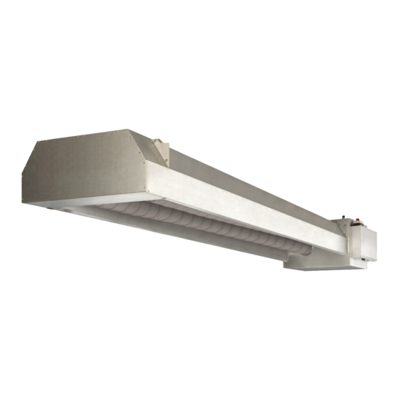
The Infra Line is an infra-red radiator system employed Der Infra Line ist ein Infrarotstrahlungssystem, das in in large halls and rooms. The Infra Line is constructed of Hallen und großen Räumen verwendet wird. Der Infra Line the following components:... - Seite 6 1.1.4 B C D 1.1.5...
- Seite 7 General Allgemeines 1.1.4 Burner module Brennermodul Gas control (2x) Gasmagnetventil (2x) Gas inlet pipe 1” Gasanschluß 1” Burner Brenner Setting for recirculation valve Einstellung Rezirkulationsklappen Flue connection with spigot butts for fluegas Abgasstutzen mit Anschlußstutzen zur analysis (optional) Abgasanalyse (Option) Flue fan motor Motor Abgasventilator Insulation...
- Seite 8 1.1.6 1.1.7...
- Seite 9 General Allgemeines 1.1.6 Rail suspension system (optional) Aufhängesystem Schiene (Wahlweise) Rail Aufhängeprofil Bolt/nut M10X16 Bolzen/Mutter M10x16 Rail coupling Verbindungsstück Aufhängeprofil 1.1.7 Eckschienen-Aufhängesystem Corner rail suspension system Schiene montiert (Wahlweise) Installed rail (optional) Aufhängeauge Suspension point Eckenmodule Corner module Gerade Module Straight module...
- Seite 10 Nominal Lenght output Elektrische Länge mbar mbar m3/h mbar Nennleistung 100/50 107,5 99,5 15,0 13,2 18xØ2,2 90/44 97,2 12,2 11,9 18xØ2,2 0,65 44-50 80/40 85,6 10,5 18xØ2,2 0,55 40-50 70/36 74,9 18xØ2,2 0,47 36-50 70/30 74,9 16,2 18xØ1,9 50/30 18xØ1,9 100-70/50 107,5/74,9 99,5/70...
-
Seite 11: Technical Specifications Technische Daten
Technical specifications Technische Daten Model description Typenbezeichnung The Infra Line is supplied with three different Infra Line wird mit drei verschiedenen Brennern burners: geliefert: - Burner 1, with a nominal adjustable capacity of 70 - Brenner 1 mit einer einstellbaren Nennleistung von to 100 kW for the models 100/50, 90/44, 80/40 70 bis 100 kW für die Typen 100/50, 90/44,... - Seite 12 1.3.1 55° 07-1054 MIN. 1250 07-1056...
-
Seite 13: Projection Planung
Strahler mindestens 4,5 Meter vom Boden intensity. entfernt aufgehängt werden. - The Infra Line heats at the living height (2 metres - Infra Line heizt einen zwei Meter über dem Boden above the floor) a strip with a width of about twice the liegenden Streifen mit eine Breite von etwa der suspension height (see diagram 1.3.1). - Seite 14 1.4.1 07-1057 1.4.2 / 3000 07-1058 1.4.3 07-1060 1.4.3 07-1059...
- Seite 15 Dimensions, weights and Abmessungen, Gewichte und technical installation data Technische Informationen 1.4.1 Dimensions burner module Abmessungen Brennermodul Burner module 68 kg Brennermodul 68 kg Dimensions in mm Maß in mm Abmessungen gerades Modul 1.4.2 Dimensions straight module 1° Erstes gerades Modul 44 kg 1st straight module 44 kg...
- Seite 16 1.4.5 Single flue set hori- Flue gas exhaust The flue gas zontal and combustion air exhaust pipes must be made Ø Article code Ø Article code of aluminium or 130/200 5990590 ALU Extension pipe stainless steel. L = 1000 The combustion 5990744 air inlet pipes can be made of...
- Seite 17 The device only has the CE approval in combination Das Gerät hat nur eine CE-Zulassung in Kombination with its flue gas system. The flue gas system includes: mit dem von MARK gelieferten Abgassystem. Das single flue set vertical or horizontal, extension pipes and Abgassystem umfasst: Dach- und Wanddurchführung, elbows.
- Seite 18 1.4.6 07-1061 1.4.7 c = c max. c = c min. a = a max. c = c1 + c2 + c3 d = d max. b = b max. a = a min. d = d min. b = b min. d = d1 + d2 + d3 b = b1 + b2 c2 (>=2 m)
- Seite 19 1.4.8 Dimension table construction sizes Infra Line Maßtabelle Baumaße Infra Line The length can vary per Infra Line model. The minimum Die Länge kann je nach Infra Line variieren. Die and maximum lengths are shown in table 1.4.8. Mindestund Höchstlängen sind in Tabelle 1.4.8 angegeben.
- Seite 20 1.4.9 L1+L2+L3 = max. 6000 Max. 2 x 90° ø130 Max. 2 x 90° ø130 L3+L4 = max. 6000 07-1063...
- Seite 21 Technische Informationen 1.4.9 Flue gas discharge and air intake Verbrennungsgasableitung und Luftzufuhr The minimum installation measurement is given for Außerdem ist ein Mindesteinbaumaß für die Montage mounting the Infra Line. von Infra Line vorgegeben. D = roof thickness D = Dachdicke...
- Seite 22 1.4.11 07-1078 1.4.12 07-1077 1.4.13 07-1080 1.4.14 07-1080...
- Seite 23 Dimensions, weights and Abmessungen, Gewichte und technical installation data Technische Informationen 1.4.11 Electrical connection (On/Off) Elektrischer Anschluß (Ein/Aus) The electrical connection must comply with the local Der elektrische Anschluß muß den geltenden and national regulations and must be fused with a Vorschriften genügen und ist mit einer Schmelzsicherung fusible cut-out of max.6A.
- Seite 24 / 3060...
-
Seite 25: Installation
Installation Installation 1.5.1 Installation Installation Upon delivery check if all the parts are present and take Kontrollieren Sie bitte die angelieferten Teile auf note of any damage. Check that you have received the Beschädigungen und Vollzäligkeit. right model. 1.5.2.1 General Allgemeines When installing the radiant heaters the applicable Bei der Installation von Gasgeräten sind die geltenden... - Seite 26 1.5.3 07-1047 1.5.3.1 07-1048 1.5.3.2 07-1049...
- Seite 27 Installation Installation 1.5.3 Step-by step plan for mounting the Infra Line with the Montageplan, in dem die Montage des Intra Line mit aid of diagrams. See 1.5.3 to 1.5.8. Hilfe von Abbildungen Schritt für Schritt erläutert wird. Sieh 1.5.3 bis 1.5.8.
- Seite 28 1.5.4 07-1065 1.5.5 07-1066 1.5.6 07-1052...
- Seite 29 Installation Installation 1.5.4 Connecting rails (option) Schienen verbinden Slide coupling piece (I=300 mm) halfway into a rail Das Verbindungsstück (I = 300 mm) zur Hälfte in length at the head side and then put them together on eine Stirnseite einer Schienenlänge schieben und the floor with bolts and nuts into manageable lengths (4 anschließend auf dem Boden mit Bolzen und Muttern to 6 metres) (see diagram 1A).
- Seite 30 1.5.7 07-1068 1.5.8 07-1068...
- Seite 31 Installation Installation 1.5.7 First straight module Erstes gerades Modul The first straight module (indicated on the module) is Das erste gerade Modul (auf dem Modul angegeben) ist equipped with an insulated interior pipe and must mit einem isolierten Innenrohr versehen und muß also therefore first be attached to the burner module.
- Seite 32 1.5.9 07-1064 07-1064-2...
- Seite 33 Installation Installation 1.5.9 Cornermodule Eckmodul A maximum of two corner modules may be used per Pro Konfiguration können maximal zwei Eckmodule configuration. A minimum of six straight modules must verwendet werden. Zwischen dem Brennermodul und be placed between the burner module and the first dem ersten Eckmodul müssen sich 12 mtr gerade corner module.
- Seite 34 1.5.10 07-1069...
- Seite 35 Installation Installation 1.5.10 Endmodule Endmodul The work order is as follows: Reihenfolge: A Slide the inversion box on the pitched connection A Die Umkehrhaube auf den Anschließmuffen vom of the previous module and screw this to the vorigen Module schieben und mittels der Schrauben attechment profile.
- Seite 36 1.6.1 1.6.2 1.6.3...
-
Seite 37: Maintenance Wartung
Maintenance Wartung 1.6.1 Prior to operation Vor der Inbetriebnahme Check if the operation of the unit cannot be influenced Prüfen Sie, ob die Funktionsweise des Gerätes nicht beeinflußt werden kann: - objects receiving direct radiant heat are not too - durch direkt angestrahlte Objekte, die sich in der Nähe close to the heater;... - Seite 38 1.6.4 07-1099 07-1100...
- Seite 39 Operation Inbetriebnahme 1.6.4 Check safe operation and output Überprüfung von Sicherheit und Wirkungsgrad After a warming-up period of approximately 30 minutes, Nach einer Aufheizzeit von etwa 30 Minuten kann man the CO2 level can be measured (table 1.2). This den CO2-Gehalt messen (Tabelle 1.2). Die Messung muß measurement must occur with the inspection panel bei geschlossenem Apparaturdeckel erfolgen.
- Seite 40 Electrical diagram Infra Line on/off...
- Seite 41 Electrical diagram Infra Line high/low...
- Seite 42 Elektrisches Schema Infra Line Ein / Aus...
- Seite 43 Elektrisches Schema Infra Line Hoch / Tief...
-
Seite 44: Operation
Operation Trouble-shooting diagramm Infra Line On/Off... - Seite 45 Inbetriebnahme Störungsdiagramm Infra Line An/Aus Liegt eine 230V Spannung an zwischen Klemmen N und L1? Liegt 230V an zwischen Klemme N und Klemme 4 der Motorschützschalter Q1.2? Schaltet der Motor- Leuchtet die Lampe schutzschalter? vom Brenner- automat? Zündelektrode verschmutzt...
- Seite 46 1.6.6 1.6.7 1.6.8...
- Seite 47 Operation Inbetriebnahme 1.6.6 Malfunctions Störungen Insufficient gas (may also be noticed with other Gaswegfall (eventuell auch an anderen Geräten devices) bemerkbar) a. turn off the main electrical switch after waiting at a Frühestens nach 5 Minuten Wartezeit den least 5 minutes. elektrischen Hauptschalter ausschalten.
- Seite 48 1.7.1 30 22 330 30 22 417 07-1070 1.7.2 30 22 215 07-1031...
- Seite 49 Maintenance Wartung 1.7.1 Maintenance Wartung At least once per year, more often if necessary: Folgende Wartungsarbeiten mindestens einmal jährlich - erforderlichenfalls auch öfter durchführen: Turn off main electrical switch and close the gas stop cock. Disassemble the burner’s interior gas system. Den elektrischen Hauptschalter ausschalten und das Check the position of the ionisation and ignition Gasabsperrventil schließen.
- Seite 50 1.8.1 06 07 604 06-1221 1.8.2 06 25 050 07-1071 1.8.3a 06 15 044 06 15 027 07-1072...
- Seite 51 Description of the equipment Gerätebeschreibung 1.8.1 Pneumatic switch Luftdruckschalter The pneumatic switch checks the transport of Der Luftdruckdifferenzschalter überwacht den combustion gases. If no or insufficient transport of Transport der Verbrennungsgase. Wird festgestellt, combustion gases is ascertained, the supply of the gas daß...
- Seite 52 1.8.3 b...
- Seite 53 Description of the equipment Gerätebeschreibung 1.8.1 Functions Funktionen Start command (switxhing 0n by ‘R’) Startbefehl (Einschaltung durch ‘R’) Operating position of burner reached Betriebsstellung des Brenners erreicht Control shutdown by ‘R’ Reglerabschaltung durch ‘R’ • Burner is immediately shut down •...
- Seite 54 1.8.4 07-1046 1.8.5 30 22 330 30 22 417 Gas inlet Gasanschluß 07-1070 1.8.6 06 08 095 06 08 097 07-1045 07-1044B...
- Seite 55 Description of the equipment Gerätebeschreibung 1.8.4 Burner assembly Brennerzusammenstellung Gastrain (1”). Gasregelstrecke. Diapharagma burnerair supply. Blende Verbrennungsluft Aluminium pipe ∆ P-measurement. Aluminiumrohr ∆ P-Messung. Adjustment flue recirculation. Einstellung Abgasrezirkulation Burnerhousing. Brennergehäuse. Flue fan motor. Motor Abgas 1.8.5 A Ignition electrode A Zündelektrode With the ignition transformer a spark is formed between Mit dem Zündtransformator wird zwischen der...
- Seite 56 1.8.7 06 31 290 07-1084 06 21 849...
- Seite 57 Description of the equipment Gerätebeschreibung 1.8.7 Servo motor High/Low Servomotor Zweistufig The servo motor is adapted for the control of the flue gas Der Stellmotor wird für die Steuerung der Rauch- circulation. The motor is mounted directly on the valve gaszirkulation verwendet.
- Seite 58 07-1101...
- Seite 59 Bracket instructions...
- Seite 60 Anleitung zu Befestigung der Verbrennungsluft und Rauchgasleitung...
- Seite 64 FAX +31 (0)598 624584 TELEFAX +49 (0)2822 97728-10 info@mark.nl info@mark.de www.mark.nl www.mark.de MARK EIRE BV MARK POLSKA Sp. z o.o COOLEA, MACROOM UL. JASNOGÓRSKA 27 CO. CORK 42-202 CZĘSTOCHOWA (POLSKA) P12 W660 (IRELAND) PHONE +48 34 3683443 PHONE +353 (0)26 45334...