Mark INFRA LINE Technisches Handbuch
Das flexibale strahlungsheizungsystem
Vorschau ausblenden
Andere Handbücher für INFRA LINE:
- Technisches handbuch (64 Seiten) ,
- Montageanleitung (24 Seiten) ,
- Montageanleitung (20 Seiten)
Inhaltsverzeichnis
Quicklinks
CE-0063 AR 3210
1.1
General
Allgemeines
1.2
Technical
Technischen
specifications
Diensten
1.3
Projection
Planung
1.4
Dimensiones
Maßskizzen
and
und
specifications
technical data
1.5
Installation
Installation
1.6
Operation/
Inbetrieb -
Faillure
nahme
1.7
Maintenance
Wartung
1.8
Equipment
Beschreibung
description
der
Komponenten
GB
Great-Britain
IE
Eire
DE
Deutschland
AT
Österreich
BE
Belgiën
TECHNICAL MANUAL INFRA LINE
TECHNISCHES HANDBUCH INFRA LINE
T H E
F L E X I B L E
D A S
F L E X I B L E
R A D I A N T
H E A T I N G
S T R A H L U N G S H E I Z U N G S Y S T E M
S Y S T E M
Inhaltsverzeichnis

Verwandte Anleitungen für Mark INFRA LINE


Inhaltszusammenfassung für Mark INFRA LINE
- Seite 1 TECHNICAL MANUAL INFRA LINE TECHNISCHES HANDBUCH INFRA LINE CE-0063 AR 3210 General Allgemeines Technical Technischen specifications Diensten Projection Planung Dimensiones Maßskizzen specifications technical data Installation Installation Operation/ Inbetrieb - Faillure nahme Maintenance Wartung Equipment Beschreibung description Komponenten Great-Britain Eire Deutschland...
- Seite 2 1.1.1 1.1.2 1.1.3...
-
Seite 3: General Allgemeines
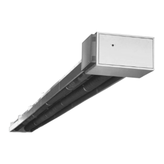
Der Infra Line The Infra Line is an infra-red radiator system employed Der Infra Line ist ein Infrarotstrahlungs-system, das in in large halls and rooms. The Infra Line is constructed Hallen und großen Räumen verwendet wird. Der Infra of the following components:... - Seite 4 1.1.4 B C D 1.1.5...
- Seite 5 General Allgemeines 1.1.4 Burner module Brennermodul Gas control Gasmagnetventil Gas inlet pipe 1" Gasanschluß 1" Burner Brenner Setting for recirculation valve Einstellung Rezirkulationsklappen Flue connection with spigot butts for fluegas Abgasstutzen mit Anschlußstutzen zur analysis (optional) Abgasanalyse (Obtion) Flue fan motor Motor Abgasventilator Insulation Isolierung...
- Seite 6 1.1.6 1.1.7 1.1.8...
- Seite 7 Nacht/Wochenendtemperatur temperature Hilfsrelais Required auxiliary relays Wahlschalter Nacht/Automat Option switch - night setting/clock setting Pro Gerät eine beleuchtete Drucktaster Illuminated push button for each Infra Line (burner (Brennerreset/Brennerstörung) reset/burner failure Steuerstromsicherung Control current fuse Sicherungsgruppe Fuse block Black bulb sensor (delivery separate) Schwarzkugelthermostat (wird löse mitgeliefert)
- Seite 8 1.2.1 Nominal Lenght output Elektrische Länge mbar mbar m3/h mbar Nennleistung 100/50 107,5 15,0 13,2 18xØ2,2 90/44 97,2 12,2 11,9 18xØ2,2 0,65 44-50 80/40 85,6 10,5 18xØ2,2 0,55 40-50 70/36 74,9 18xØ2,2 0,47 36-50 70/30 74,9 16,2 18xØ1,9 50/30 18xØ1,9 100-70/50 107,5/74,9 100/70...
-
Seite 9: Tecnical Specifications Technische Daten
Tecnical specifications Technische Daten 1.2.1 Model description Typenbezeichnung The Infra Line is supplied with three different Infra Line wird mit drei verschiedenen Brennern burners: geliefert: - Burner 1, with a nominal adjustable capacity of 70 - Brenner 1 mit einer einstellbaren Nennleistung von to 100 kW for the models 100/50, 90/44, 80/40 70 bis 100 kW für die Typen 100/50, 90/44,... - Seite 10 1.3.1 07-1054 07-1056...
-
Seite 11: Projection Planung
- Zur Vermeidung einer zu hohen Strahlungsintensität radiation intensity. sollte der Strahler mindestens 4,5 Meter vom - The Infra Line heats at the living height (2 metres Boden entfernt aufgehängt werden. above the floor) a strip with a width of about twice - Infra Line heizt einen zwei Meter über dem Boden... - Seite 12 1.4.1 07-1057 1.4.2 07-1058 1.4.3 07-1060 1.4.3 07-1059...
- Seite 13 Dimensions and weights Abmessungen und Gewichten 1.4.1 Dimensions burner module Abmessungen Brennermodul Burner module 68 kg Brennermodul 68 kg Dimensions in mm Maß in mm Abmessungen gerades Modul Dimensions straight module 1.4.2 1st straight module 50 kg 1° Erstes gerades Modul 50 kg 1°...
- Seite 14 1.4.5 07-1088 90˚ Uitw. ø130 59 90 542 07-1090 05 40 626 59 90 565 ø130 ø130 ø130 l=500 59 90 541 l=1000 59 90 540 07-1091 59 90 590 07-1087...
-
Seite 15: Dimensions Fluesystem Abmessungen Abgassystem
Dimensions fluesystem Abmessungen Abgassystem 1.4.5 Dimensions flue gas exhaust elements Abmessungen der Rauchgasabzugs-elemente Measuring butt (page 40) Meßstutzen (Blatt 40) 1C Bend piece 90° Krümmer 90°C 1D Bend piece 45° Krümmer 45°C 1E Roof single pipe system Doppelrohr über Dach Wall single pipe system Doppelrohr über Wand The single pipes (roof or wall) are concentric with an... - Seite 16 1.4.6 07-1061 1.4.7 c = c max. c = c min. a = a max. c = c1 + c2 + c3 d = d max. b = b max. a = a min. d = d min. b = b min. d = d1 + d2 + d3 b = b1 + b2 c2 (>=2 m)
-
Seite 17: Dimensions/Weights Abmessungen/Gewichten
Dimension table construction sizes Infra Line Maßtabelle Baumaße Infra Line 1.4.8 The length can vary per Infra Line model. The minimum Die Länge kann je nach Infra Line variieren. Die Mindest- and maximum lengths are shown in table 1.4.8. und Höchstlängen sind in Tabelle 1.4.8 angegeben. - Seite 18 1.4.9 MAX 6x90˚ ø130 L3 + L4 = MAX 6000 MAX 6x90˚ ø130 L1 + L2 = MAX 6000 07-1089 DU= 200 DU= 130 07-1063...
-
Seite 19: Dimensions Abmessungen
Dimensions Abmessungen 1.4.9 Verbrennungsgasableitung und Luftzufuhr Flue gas discharge and air intake Außerdem ist ein Mindesteinbaumaß für die Montage The minimum installation measurement is given for von Infra Line vorgegeben. mounting the Infra Line. D = Dachdicke D = roof thickness... - Seite 20 1.4.10 a G 25 G 20 100-50 90-44 80-40 Druck- Wobbe-Index Kurve, Erdgas fur Warmlufterzeuger. Modell 70-36 Infra Line 100-50 Infra Line 90-44 Infra Line 80-40 Infra Line 70-36 Infra Line 100/70-50 10.0 11.00 11.52 12.00 13.00 14.00 14.08 15.00 Wobbe-Index (Wo) 8.00...
- Seite 21 1.4.10 a Burner pressure diagramm Düsendruckgrafik Type 100/50, 90/44, 80/40, 70/36 and 100/50, 90/44, 80/40, 70/36 und 100/70-50 100/70-50...
- Seite 22 1.4.10 b G 25 G 20 70-30 50-30 Druck- Wobbe-Index Kurve, Erdgas fur Warmlufterzeuger. Modell Infra Line 70-30 Infra Line 50-30 10.0 11.00 11.52 12.00 13.00 14.00 14.08 15.00 Wobbe-Index (Wo) 8.00 9.00 9.01 10.00 10.48 11.00 Nennwärmebelastung (kWh/m ) Ho 15˚C...
- Seite 23 1.4.10 b Burner pressure diagramm Düsendruckgrafik Type 70/30 and 50/30 70/30 und 50/30...
- Seite 24 1.4.11 07-1078 1.4.12 07-1077 1.4.13 07-1080 1.4.14 Reglung (Zwei stufig) 07-1080...
- Seite 25 1.4.11 Electrical connection (On/Off) Elektrischer Anschluß (Ein/Aus) The electrical connection must comply with the local Der elektrische Anschluß muß den geltenden and national regulations and must be fused with a Vorschriften genügen und ist mit einer fusible cut-out of max.6A. Schmelzsicherheit von max.
- Seite 27 Istallation Istallation Installation Installation 1.5.1 Upon delivery check if all the parts are present Kontrolieren Sie bitte Wareneingan die angelieferten and take note of any damage. Check that you have Teile auf Beschädigungen und Vollzäligkeit received the right model. 1.5.2.1 General Allgemeines When installing the radiant heaters the applicable...
- Seite 28 1.5.3 07-1047 1.5.3.1 07-1048 1.5.3.2 07-1049...
- Seite 29 Operation Inbetriebnahme 1.5.3 Step-by step plan for mounting the Infra Line with the Montageplan, in dem die Montage der Intra Line mit aid of diagrams. See 1.5.3 to 1.5.8. Holfe von Abbildungen Schritt für Schritt erläutert wird. Sieh 1.5.3 bis 1.5.8.
- Seite 30 1.5.4 07-1065 1.5.5 07-1066 1.5.6 07-1052...
- Seite 31 Operation Inbetriebnahme 1.5.4 Connecting rails (option) Schienen verbinden Slide coupling piece (I=300 mm) halfway into a rail Das Verbindungsstück (I = 300 mm) zur Hälfte in length at the head side and then put them together on eine Stirnseite einer Schienenlänge schieben und the floor with bolts and nuts into manageable lengths anschließend auf dem Boden mit Bolzen und Muttern (4 to 6 metres) (see diagram 1A).
- Seite 32 1.5.7 07-1068 1.5.8 07-1068...
-
Seite 33: Installation
Installation Installation 1.5.7 First straight module Erstes gerades Modul The first straight module (indicated on the module) is Das erste gerade Modul (auf dem Modul angegeben) equipped with an insulated interior pipe and must the- ist mit einem isolierten Innenrohr versehen und muß refore first be attached to the burner module. - Seite 34 1.5.9 07-1064 07-1064-2...
- Seite 35 Installation Installation 1.5.9 Cornermodule Eckmodul A maximum of two corner modules may be used per Pro Konfiguration können maximal zwei Eckmodule configuration. A minimum of six straight modules must verwendet werden. Zwischen dem Brennermodul und be placed dem ersten Eckmodul müssen sich mindestens sechs gerade Module befinden.
- Seite 36 1.5.10 07-1069...
- Seite 37 Installation Installation 1.5.10 Endmodule Endmodul The work order is as follows: Reihenfolge: A Slide the inversion box on the pitched connection A Die Umkehrhaube auf den Anschließmuffen vom of the previous module and screw this to the vorigen Module schieben und mittels die Schraube attechment profile.
- Seite 38 1.6.1 1.6.2 1.6.3...
-
Seite 39: Maintenance Wartung
Maintenance Wartung 1.6.1 Prior to operation Vor der Inbetriebnahme Check if the operation of the unit cannot be influenced Prüfen Sie, ob die Funktionsweise des Gerätes nicht beeinflußt werden kann: objects receiving direct radiant heat are not too durch direkt angestrahlte Objekte, die close to the heater;... - Seite 40 1.6.4 07-0000 1.6.5...
- Seite 41 Operation Inbetriebnahme 1.6.4 Check safe operation and output Überprüfung von Sicherheit und Wirkungs-grad After a warming-up period of approximately 30 minu- Nach einer Aufheizzeit von etwa 30 Minuten kann man tes, the CO level can be measured (table 1.2.1). This den CO -Gehalt messen (Tabelle 1.2.1).
-
Seite 43: Operation
Operation Trouble-shooting diagramm Infra Line On/Off... - Seite 45 Inbetriebnahme Störungsdiagramm Infra Line An/Aus...
- Seite 46 1.6.6 1.6.7 1.6.8...
- Seite 47 Operation Inbetriebnahme Malfunctions Störungen 1.6.6 Insufficient gas (may also be noticed with other Gaswegfall (eventuell auch an anderen Geräten devices) bemerkbar) a. turn off the main electrical switch after waiting at a Frühestens nach 5 Minuten Wartezeit den least 5 minutes. elektrischen Hauptschalter ausschalten.
- Seite 48 1.7.1 30 22 330 30 22 417 07-1070 1.7.2 30 22 215 07-1031...
- Seite 49 Maintenance Wartung 1.7.1 Maintenance Wartung At least once per year, more often if necessary: Folgende Wartungsarbeiten mindestens einmal jährlich Turn off main electrical switch and close the gas stop - erforderlichenfalls öfter - durchführen: cock. Disassemble the burner's interior gas system. den elektrischen Hauptschalter ausschalten und das Check the position of the ionisation and ignition Gasabsperrventil schließen.
- Seite 50 1.8.1 06 07 604 06-1221 1.8.2 06 25 050 07-1071 1.8.3a 06 15 044 06 15 027 07-1072...
- Seite 51 Description of the equipment Gerätebeschreibung 1.8.1 Pneumatic switch Luftdruckschalter The pneumatic switch checks the transport of Der Luftdruckdifferenzschalter überwacht den Transport combustion gases. If no or insufficient transport of der Verbrennungsgase. Wird festgestellt, combustion gases is ascertained, the supply of the daß...
- Seite 52 1.8.3 b...
- Seite 53 Description of the equipment Gerätebeschreibung 1.8.1 Functions Funktionen Start command (switxhing 0n by ‘R’) Startbefehl (Einschaltung durch ‘R’) Operating position of burner reached Betriebsstellung des Brenners erreicht Control shutdown by ‘R’ Reglerabschaltung durch ‘R’ • Burner is immediately shut down •...
- Seite 54 1.8.4 07-1046 1.8.5 30 22 330 30 22 417 Gas inlet Gasanschluß 07-1070 1.8.6 06 08 097 06 08 095 07-1045 07-1044...
- Seite 55 Description of the equipment Gerätebeschreibung 1.8.4 Burner assembly Brennerzusammenstellung Gastrain (1”). Gasregelstrecke. Diapharagma burnerair supply. Blende Verbrennungsluft Aluminium pipe ∆ P-measurement. Aluminiumrohr ∆ P-Messung. Adjustment flue recirculation. Einstellung Abgasrezirkulation Burnerhousing. Brennerbehausung. Flue fan motor. Motor Abgas 1.8.5 A Ignition electrode A Zündelektrode With the ignition transformer a spark is formed Mit dem Zündtransformator wird zwischen der...
- Seite 56 1.8.7 06 31 290 07-1084 06 21 849...
- Seite 57 Description of the equipment Gerätebeschreibung 1.8.7 Servo motor High/Low Servomotor Zweistufig The servo motor is adapted for the control of the flue Der Servomotor wird für die Steuerung der Rauch - gas circulation. The motor is mounted directly on the gaszirkulation verwendet.