Interlogix VE1012 Series Installationsanleitung
Inhaltsverzeichnis
Verfügbare Sprachen
Verfügbare Sprachen
Quicklinks
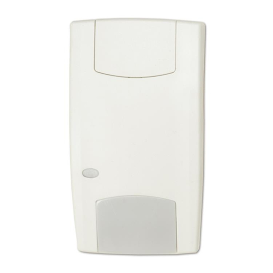
VE1012 Series PIR Detector Installation Sheet
EN DE ES FR
IT
NL PL PT SV
1
3
1
© 2019 UTC Fire & Security Americas Corporation, Inc.
J2
1 / 26
2
J1
Not used
J2
LED on
LED off
J3 and J4
See Figure 7
J5
Terminal 8 = D/N
Terminal 8 = remote test
J6
CV + polarity
CV − polarity
P/N 146414999-2 (ML) • REV G • ISS 08MAR19
(1)
(2)
(3)
Inhaltsverzeichnis

Verwandte Anleitungen für Interlogix VE1012 Series


Inhaltszusammenfassung für Interlogix VE1012 Series
- Seite 2 12 m range (39 ft. 4 in.) 2.4 m (7 ft. 10 in.) (optimum) 3.67 (12 ft.) 2.0 m (39 ft. 4 in.) (3) 5 curtains (4) 7 curtains (5) 5 curtains 6 m range 6 m range 12 m range 2B-3B 7B-8B (6) 7 curtains...
-
Seite 6: Steckbrückeneinstellungen
Bei EN50131 Grad 3 Installationen darf die DE: Installationsanweisungen Montageposition C nicht verwendet werden. Steckbrückeneinstellungen Einführung Siehe Abbildung 3 für die Steckbrückenpositionen (J1-6) im Die Serie VE1012/VE1012AM besteht aus PIR/PIR-AM- Melder. Bewegungsmeldern. Letztere verfügen über einen patentierten Spiegel sowie Pyro- und Signalverarbeitungstechnologie. J1: Nicht verwendet Installationsanleitungen J2: PIR aktiviert die LED... -
Seite 7: Led-Anzeige
• Verändern Sie den Erfassungsbereich, indem Sie Teile SW 2: AM-Empfindlichkeit der Abdeckung herausbrechen (graue Darstellung in Ein: Erweiterte AM-Empfindlichkeit. Der Melder signalisiert Abbildung 6, Punkt 1). Die entsprechenden eine Annäherung und die Maskierung des Meldefensters Vorhangfragmente sind in Abbildung 6, Punkt (Werkseinstellung).