Inhaltsverzeichnis
Werbung
Verfügbare Sprachen
Verfügbare Sprachen
Quicklinks
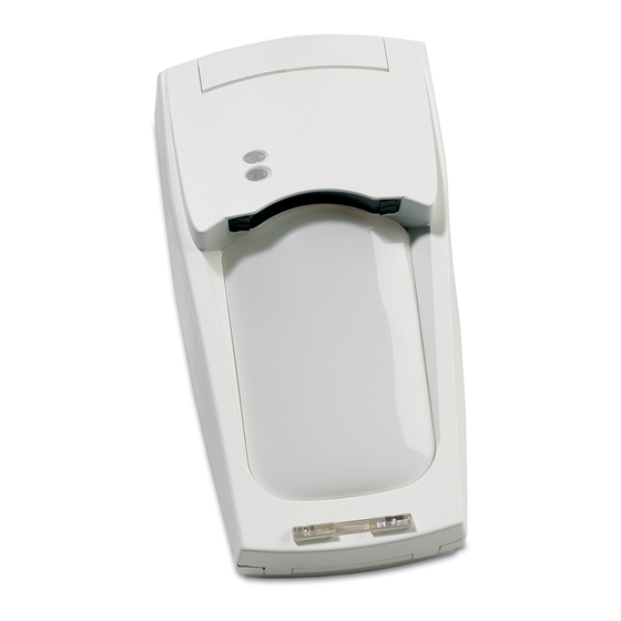
VE700AM Series Vector Enhanced Motion
Sensor Installation Sheet
EN DA DE ES FR
IT
1
4
A
A
C
C
B
B
© 2018 UTC Fire & Security Americas Corporation, Inc.
NL PL PT SV
2
5
DIN 7996
(3.5 mm x 35 mm)
D
D
6
C V
DAY/NIGHT
WALK TEST
3
A
A
B
B
A
B
NIGHT
DAY
ON
OFF
Control panel
C
C
C
C
A
D
B
D
10
10
10
11
11
11
P/N 149973999-3 (ML) • REV G • ISS 20DEC18
D
D
10
11
Werbung
Inhaltsverzeichnis

Verwandte Anleitungen für Interlogix VE700AM Serie


Inhaltszusammenfassung für Interlogix VE700AM Serie
- Seite 1 VE700AM Series Vector Enhanced Motion Sensor Installation Sheet EN DA DE ES FR NL PL PT SV DIN 7996 (3.5 mm x 35 mm) NIGHT DAY/NIGHT WALK TEST Control panel © 2018 UTC Fire & Security Americas Corporation, Inc. P/N 149973999-3 (ML) • REV G • ISS 20DEC18...
- Seite 2 VE735AM VE736AM ALARM ALARM TAMPER TAMPER DAY / WALK DAY / WALK +12V NC C NC C NC C NIGHT TEST NC C TEST NIGHT 9 10 11 REMOTE REMOTE TEST TEST ---- ---- (5) (6) (7) P/N 149973999-3 (ML) • REV G • ISS 20DEC18 2 / 60...
- Seite 3 Panel Panel Dual Loop Zone Dual Loop Zone ALARM TAMPER ALARM TAMPER ALARM TAMPER ALARM TAMPER SPARE SPARE SPARE SPARE P/N 149973999-3 (ML) • REV G • ISS 20DEC18 3 / 60...
- Seite 4 1.8-3.0 m (5.9-9.8 ft.) (3.3 ft.) 60 m (197 ft.) P/N 149973999-3 (ML) • REV G • ISS 20DEC18 4 / 60...
- Seite 5 1 2 3 4 5 7 8 9 10 11 1 2 3 4 5 7 8 9 10 11 18 m 18 m 18.5 m 18.5 m 20 m 2.3 m (7.5 ft.) Note: For UL compliant installations do not mount the motion sensor below 8 ft mounting height P/N 149973999-3 (ML) •...
-
Seite 6: Mounting The Detector
ST400 Mounting the detector Lift off the custom insert and remove the enclosed screw (Figure 1). Using a screwdriver, carefully prise open the detector (Figure 2). SB01 Remove the interior part (Figure 3). Fix the base to the wall between 1.8 m and 3.0 m (5.9 to 9.8 ft.) from the floor. - Seite 7 loop increases to 9.4 kΩ, indicating an alarm. When Figure 11 the detector housing is opened, the tamper circuit (1) AM DIP switch (4) COM port opens and the dual loop is interrupted, indicating a (2) Tamper (5) J1: PIR sensitivity tamper alarm.
- Seite 8 AM DIP switches Testing the anti-masking functionality See Figure 11, item 1. AM start-up sequence: When the VE700AM is powered, the AM circuitry will wait until the cover of the detector is properly mounted. Table 2: AM DIP switches Function DIP switch On DIP switch Off As soon as the cover is mounted, the AM circuitry will monitor...
-
Seite 9: General Information
The red and yellow LEDs are blinking simultaneously Latching then the field of view is obstructed and is insufficient When using multiple detectors in a single loop, wire for to verify an alarm. day/night and walk test inputs, as shown in Figure 6. There are two options: •... -
Seite 10: Specifications
SB01 swivel-mount bracket (optional) Glossary When it is not possible to mount the detector on a wall, use the Alarm memory. A storage medium located on the detector that SB01 to mount it on the ceiling. can record signals generated by the detector. Anti-masking (AM). - Seite 11 Viewing angle www.utcfssecurityproducts.eu/recycle/ IP/IK rating IP30 IK02 Contact information Regulatory information www.utcfireandsecurity.com or www.interlogix.com Manufacturer UTC Fire & Security Americas Corporation, Inc. For customer support, see www.utcfssecurityproducts.eu 3211 Progress Drive, Lincolnton, NC, 28092, USA Authorized EU manufacturing representative: UTC Fire & Security B.V.
- Seite 12 Vælg de ønskede indstillinger for jumper og DIP-switch J3: Dobbelt balanceret sløjfe (kun tilgængelig i VE735AM) (se “Indstilling af detektoren” nedenfor). Giver mulighed for tilslutning til alle typer AIA-centraler, også med dobbelt balanceret sløjfe, uden brug af løse Udskift den indre del (Figur 9). endemodstande.
-
Seite 13: Test Af Anti-Mask-Funktionen
Afslør aldrig detektorens tilstand over for en indbrudstyv via OFF: "Aktiv lav" giver "Aktiv lav"-logik, der aktiverer input af typen gangtest og dag/nat. lysdioderne. DIP-switch 2: Dørklokke DIP-switch 2: AM-følsomhed ON: Vælger et højere niveau for AM-følsomhed. AM-relæet Se figur 12. reagerer inden for 6 sekunder. -
Seite 14: Generelle Oplysninger
IEC60825-1. Øjets blinkerefleks er hurtig nok til at Lysdiodernes statusvisning forhindre eventuel permanent beskadigelse af øjet. Tabel 3: Lysdiodevisning Laserprikken angiver detektorens kalibrering (Figur 18). Hvis prikken på væggen afviger fra centret af det ønskede Rød Detektor-status Afstilling dækningsområde, 1 m over gulvet, løsnes bagpladens lysdiode lysdiode fikseringsskruer (se figur 4), og de tre justeringsskruer i... - Seite 15 Hvis der skiftes tilbage til nat mode, slettes hukommelsen, og Ekstern test lysdioden slukkes. Terminal 12: Aktivering af gangtesten vil ikke rydde hukommelsen. Hvis gangtesten deaktiveres, bliver gemte alarmer vist igen. Alarmrelæ: Valg af dækningsmønster 3 sek. VE700AM OK Se figur 21 og 22. Dækningsmønstret kan ændres, så...
-
Seite 16: Kontaktinformation
Alarmudgang 80 mA ved 30 V maks., resistiv Kontaktinformation (ohmsk belastning) Sabotagekontaktens udgang 80 mA ved 30 V maks., resistiv www.utcfireandsecurity.com eller www.interlogix.com Fejludgang 80 mA ved 30 V maks., resistiv For kundesupport se www.utcfssecurityproducts.dk (ohmsk belastning) Alarmtid 3 sek. -
Seite 17: Montage Des Melders
Montage des Melders Mittlere Empfindlichkeit: In den meisten Fällen die richtige Einstellung (Werkseinstellung) (Position 2). Nehmen Sie den individuellen Einsatz ab und entfernen Sie die darin befindliche Schraube (Abbildung 1). Hohe Empfindlichkeit: Für Situationen mit besonders hohem Risiko geeignet. Empfohlen für Heben Sie mit einem Schraubendreher vorsichtig den die Verwendung in Korridoren (Position 3). -
Seite 18: Pir-Dip-Schalter
PIR-DIP-Schalter Funktion DIP-Schalter Ein DIP-Schalter Aus 4. Wie der AM- oder TF- Relais: Relais:* Siehe Abbildung 11, Position 7. Ausgang signalisiert wird Alarm Alarm AM + Tabelle 1: PIR-DIP-Schalter TF + Funktion DIP-Schalter Ein DIP-Schalter Aus * Werkseinstellung 1. Polarität Aktiv-High* Aktiv-Low 2. - Seite 19 Sobald die Abdeckung angebracht ist, überwacht der AM- Nachdem Sie den Vorhang durchquert haben, gilt Schaltkreis das Gehäuse und den umgebenden Bereich und Folgendes: speichert die empfangenen Signale als Referenzwerte. Dieser Die rote LED ist EIN (Abbildung 20, Position 1): in Vorgang dauert 75 Sekunden.
-
Seite 20: Allgemeine Informationen
Nicht verwendete Vorhänge, die in Richtung von Wänden oder Zurücksetzen des Status Melderstatus Gelbe Rote Fenstern zeigen, welche sich in der unmittelbaren Nähe des Melders befinden, sollten abgedeckt werden. Gespeicherter PIR Umschalten auf Alarm: Folge- Unscharfbetrieb Warnung: Wenn Sie die Aufkleber entfernen, kann dadurch alarmkennung die Spiegeloberfläche beschädigt werden! AM-Alarm... -
Seite 21: Technische Daten
Selbsttest: VE700AM führt eine kontinuierliche Prüfung der Unscharf/Tagbetrieb. Der Melder löst kein Alarmsignal und PIR- und AM-Schaltkreise durch. Ein Defekt wird als keine Meldung aus, wenn er eine Person im technischer Fehler ausgegeben. Erfassungsbereich detektiert. Vorhänge. Eine vertikale kontinuierliche Schicht von Erfassungszonen. -
Seite 22: Instrucciones Para La Instalación
17 la conexión de varios dispositivos. Kontaktinformation Seleccione el puente que desee y la configuración de los conmutadores DIP (consulte “Configuración del detector” www.utcfireandsecurity.com oder www.interlogix.com más adelante). Kontaktinformationen für den Kundendienst finden Sie unter www.utcfssecurityproducts.de Vuelva a colocar la pieza interior (figura 9). - Seite 23 Puentes Bucle doble El bucle de tamper y alarma se puede supervisar con J1: Sensibilidad de PIR dos cables. Modifica el retardo de la alarma con la distancia (la velocidad En una situación normal (sin alarma), la impedancia del algoritmo de decisión); cuanto mayor sea la sensibilidad, del bucle doble es 4,7 kΩ.
- Seite 24 Activado: después de un periodo de inhibición de 40 Conmutador DIP 4: LED segundos, se restablece el estado de AM o FT cuando se Activado: activa ambos LED en el detector en todo momento. genera una alarma PIR. Desactivado: pone a ambos indicadores LED bajo el control de Desactivado: restablece el estado de AM o FT después de una las entradas de prueba de paseo y de día/noche.
-
Seite 25: Información General
figura 19. Una vez que el punto esté alineado Estado del detector Restablecimiento correctamente, vuelva a apretar los tornillos de fijación de amarillo rojo la base. Tensión alta/baja Aplicar el voltaje adecuado Retire la herramienta de alineación y vuelva a colocar la cubierta. - Seite 26 Al cambiar de nuevo al modo de noche se borra la memoria y Prueba remota se apaga el indicador LED. Terminal 12: La activación de la prueba de paseo no borra la memoria de alarma. La desactivación de la prueba de paseo hace que la indicación de alarmas memorizadas vuelva a aparecer.
-
Seite 27: Especificaciones
Información normativa Modo Día (modo desarmado). No es necesario que el detector genere una señal o mensaje de alarma cuando lo activa Fabricante UTC Fire & Security Americas Corporation, Inc. una persona que camina delante de él. 3211 Progress Drive, Lincolnton, NC, 28092, EE. Máscara. -
Seite 28: Fr: Manuel D'installation
Información de contacto Alignez le détecteur. Reportez-vous à la section « Alignement du faisceau et test de marche du détecteur » www.utcfireandsecurity.com o www.interlogix.com en page 30. Para acceder al servicio técnico, consulte Retirez les œillères et placez les autocollants selon les www.utcfssecurityproducts.es... - Seite 29 Le détecteur distingue la direction de l’intrus pendant la J3 : Boucle double (disponible uniquement sur VE735AM) journée. Désactivez cette option en désactivant le carillon du Elle est utilisée pour régler le relais d’alarme et détecteur. Lorsque le carillon est activé, le détecteur déclenche d’autoprotection.
- Seite 30 N’indiquez jamais l’état du détecteur à un intrus via les AVERTISSEMENT ! Ne regardez pas directement le voyants. faisceau du laser. La puissance de sortie est inférieure à 1 mW. En Commutateur DIP 2 : Sensibilité d’anti-masque conséquence, le laser du VE710 a été classé comme un laser de classe 2, conformément à...
-
Seite 31: Informations Générales
Identification de l’état du détecteur via les Réglage de la mémoire d’alarme voyants Voir figure 6. En mode jour, un voyant clignotant indique le ou les détecteurs Tableau 3 : Indication du voyant qui ont déclenché une alarme en mode nuit. Etat du détecteur Réinitialisation Voyant... -
Seite 32: Spécifications Techniques
Test à distance Mode nuit. Le détecteur génère un signal ou message d’alarme lorsqu’il détecte une personne dans son champ Borne 12: de vision. Problème technique (PT). Signal ou message de défaut généré sur le relais AM lorsqu’une erreur apparaît sur le détecteur. -
Seite 33: Informations De Contact
Attenzione nella figura. Informations de contact Collegare il rilevatore. Vedere figura 7 e 8. www.utcfireandsecurity.com ou www.interlogix.com Selezionare le impostazioni desiderate dei ponticelli e dei Pour contacter l'assistance clientèle, voir commutatori DIP switch (sezione “Impostazione del www.utcfssecurityproducts.fr/mail_support.htm... - Seite 34 10. Inserire i tappi di protezione dagli insetti (figura 10, Circuito di allarme e antimanomissione isolati passo 1). (impostazione di fabbrica) 11. Chiudere il coperchio (passo 2). Il relè di manomissione è isolato dal relè di allarme. Il resistore di fine linea del circuito antimanomissione è 12.
- Seite 35 Commutatore DIP switch 3: Reset dell’uscita AM/TF Commutatore DIP switch 3: Direzione controllo giorno Vedere figura 13. Il rilevatore VE700AM consente il reset di un allarme antimascheramento solo dopo aver accertato che la causa ON: l’allarme scatta quando l’intruso procede da sinistra a dell’allarme è...
-
Seite 36: Informazioni Generali
Il punto luminoso generato dal laser indica l’allineamento Identificazione dello stato del rilevatore del prodotto (figura 18). Se il punto sulla parete si discosta tramite i LED dal centro dell’area di rilevazione desiderata e da 1 m rispetto al pavimento, allentare le viti di fissaggio della Tabella Indicatori LED base (figura 4) e usare le tre viti di regolazione nella base... - Seite 37 Impostazione della memoria di allarme Test remoto: questo test consente di verificare il VE700AM dalla centrale. Usare il morsetto 12 per attivarlo. Il VE700AM Vedere figura 6. attiva il relè allarme se il risultato del test è positivo e il relè antimascheramento se il risultato del test è...
-
Seite 38: Nl: Installatie Handleiding
Contatto per informazioni (morsetti 10-11-12) Alta da 3,5 a 15 V Min 1,8 m — max 3,0 m Altezza di montaggio www.utcfireandsecurity.com o www.interlogix.com Gamma velocità bersaglio 10 cm/s — 4 m/s Per l'assistenza clienti, vedere www.utcfssecurityproducts.it Relè di allarme Il relè... - Seite 39 De detector monteren Hoge gevoeligheid: te gebruiken in situaties met verhoogd risico. Aanbevolen voor gebruik in Til het inzetstuk omhoog en verwijder de aanwezige gangen (item 3). schroef (figuur 1). Wrik de detector voorzichtig open met een J2: Gordijnlocatiemodus (CLM) schroevendraaier (figuur 2).
- Seite 40 PIR dipswitches Functie Dipswitch Aan Dipswitch Uit 4. Hoe een AM- of TF- Relais: Relais:* Zie figuur 11, item 7. uitgang melden? Alarm Alarm AM + Tabel 1: PIR dipswitches TF + Functie Dipswitch Aan Dipswitch Uit * Fabrieksprogrammering 1. Polariteit Actieve hoge* Actieve lage 2.
-
Seite 41: Algemene Informatie
ontvangen signaalniveaus opslaan als referentieniveaus. Dit Er zijn twee mogelijkheden: • duurt ongeveer 75 seconden. Gedurende deze periode moet Als het knipperen begon aan het einde van het de omgeving vrij blijven van bewegingen en objecten die detectiegebied, dient u de laserstraal meer naar links tijdelijk binnen 50 cm van de detector worden geplaatst. - Seite 42 Vergrendelen Om de sabotagebehuizing mogelijk te maken, moet de schroef die in figuur 4, worden bevestigd. Bij het gebruik van meerdere detectors in een enkelvoudige lus, bedraadt u voor Dag/nacht (D/N) en Looptest (WT), zoals Bij hoekbevestiging gebruikt u de ST400 voor sabotagebehuizing (figuur 25).
-
Seite 43: Technische Specificaties
Aansluitspanning 9 tot 15 V (12 V nominaal) Piek-tot-piek rimpel 2 V (bij 12 V ) Contactgegevens Huidig stroomverbruik: www.utcfireandsecurity.com of www.interlogix.com Normale werking in bedrijf 20 mA Alarm 24 mA Voor klantenondersteuning, zie www.utcfssecurityproducts.nl Maximum 34 mA Controle-ingangsspanning Lage 0 tot 1.5 V... - Seite 44 10. Wsuń zaślepki zabezpieczające przed owadami (rys. 10, PL: Instrukcja instalacji pozycja 1). 11. Zamknij pokrywę (pozycja 2). 12. Przykręć śrubę (jeśli wymagana) i załóż pokrywkę czujki Wprowadzenie (pozycja 3). VE735AM i VE736AM to czujki ruchu PCP-AM. Zastosowano w nich sprawdzoną i opatentowaną technologię detekcji podczerwieni pasywnej (PCP), z wielokanałowym Konfiguracja czujki antymaskowaniem (AM).
- Seite 45 Wyłączony: Alarm, kiedy intruz przemieszcza się z prawa na Oddzielne linie alarmu i sabotażowa (ustawienia lewo. fabryczne) Aby określić kierunek lewy i prawy, należy ustawić się plecami Przekaźnik sabotażowy jest odizolowany od do czujki. przekaźnika alarmowego. Rezystor końca linii w obwodzie sabotażowym jest zwarty.
- Seite 46 Wyłączony: Zeruje stan AM lub TF po alarmie PCP, kiedy Kalibracja bez kalibratora system pracuje w trybie dziennym i testu czujek. Żółta Patrz Rysunek 19. dioda LED zacznie szybko migać. Jeśli system pracuje w trybie nocnym, żółta dioda LED zgaśnie, a system zostanie Włóż...
-
Seite 47: Informacje Ogólne
Wybór charakterystyki i zasięgu Patrz rys. 21 i 22. Charakterystykę przestrzenną i zasięg można zmieniać w celu dopasowania do określonych wymogów, stosując (dołączone) naklejki na lustra, jak pokazano na rysunku. Zaleca się Przełącz w tryb dzienny Zablokowany alarm PCP: 1. zasłanianie nieużywanych kurtyn, które są... -
Seite 48: Słownik Pojęć
Tryb nocny (tryb zazbrojenia). Czujka generuje sygnał lub Zdalny test komunikat alarmowy, gdy zostanie aktywowana przez Zacisk 12: osobę przechodzącą przed nią. Test zdalny. Centrala monitoruje czujnik czujki oraz jej wewnętrzny układ przetwarzania sygnału. Autotest. Sama czujka monitoruje swój czujnik oraz Przekaźnik alarmowy: wewnętrzny układ przetwarzania sygnału. -
Seite 49: Conselhos De Instalação
Informacje kontaktowe Seleccione o jumper desejado e as configurações do DIP switch (ver “Configuração do detector” abaixo). www.utcfireandsecurity.com lub www.interlogix.com Volte a colocar a parte de dentro (Figura 9). Informacje na temat pomocy technicznej można znaleźć na Alinhe o detector. Consulte “Alinhamento de beam e walk- stronie www.utcfssecurityproducts.pl... - Seite 50 Existem três sensibilidades PIR diferentes. DIP switches PIR Sensibilidade baixa: Utilizar onde há risco de falsos Ver Figura 11, item 7. alarmes. Não utilizar em aplicações de longo alcance (>20 m / 65,6 pés) ou aplicações de Tabela 1: DIP switches PIR cortina simples (item 1).
- Seite 51 Teste da funcionalidade anti-máscara Função DIP switch On DIP switch Off (Ligado) (Desligado) Sequência de arranque de AM: Quando o VE700AM é ligado, Após walk test Reinicialização 3. Reinicializar AM ou TF o circuito AM aguarda até a tampa do detector estar autorizada* adequadamente montada.
-
Seite 52: Informação Geral
Informação geral Depois de atravessar a área ocupada pelo beam, se: O LED vermelho estiver ligado (figura 20, item 1), o Em primeiro lugar, defina a polaridade de activação da alinhamento está OK. Nota: tensão de controlo (CV) utilizando o DIP switch 1. O detector Os LEDs vermelho e amarelo estiverem a piscar está... - Seite 53 Tamper de remoção e abertura No alarme PIR seguinte , o sistema reinicializa se todos os níveis de referência estiverem dentro dos limites O detector incorpora um tamper de remoção e de abertura especificados. (compatível com EN 50131-2-2). • Reinicialização automática. Após um período de inibição de 40 segundos, reinicializa-se automaticamente após um É...
-
Seite 54: Informação De Contacto
PARA SEREM VENDIDOS E INSTALADOS Informação de contacto dos produtos POR PROFISSIONAIS QUALIFICADOS. A UTC FIRE & SECURITY NÃO PODE www.utcfireandsecurity.com ou www.interlogix.com APRESENTAR QUALQUER GARANTIA DE QUE QUALQUER PESSOA OU ENTIDADE Para assistência ao cliente, consulte QUE COMPRE OS SEUS PRODUTOS, www.utcfssecurityproducts.eu... - Seite 55 i Figur 21, punkt 1). Det här är den rörelse som detekteras bäst Hög känslighet: Använd denna inställning för med PIR-detektorer. högriskinstallationer. Den här inställningen är lämplig för användning i korridorer (punkt 3). Montering av detektorn J2: Inställning av ridåerna Lyft av luckan och ta bort den bifogade skruven (figur 1).
- Seite 56 För att aktivera Fjärrtest ska en styrspänning (+12 V) anslutas Av: Normal AM-känslighet. AM-relä reagerar inom till skruv 12 (Remote test). 12 sekunder. Av: För att aktivera Nattläge ska en styrspänning (0 V) DIP switch 3: Återställning av AM / TF (tekniskt fel) anslutas till skruv 10 (Day/Night).
-
Seite 57: Allmän Information
Ta bort laserverktyg och sätt fast fronten. Återställning Röd Detektor-status Genomför en gångtest. Kontrollera att den röda lysdioden Gångtest efter 40 s eller aktiveras vid gångtest. AM larm styrning. Se Tabell 2 på sidan 56, Utan laserverktyg DIP switch 3 Se figur 19. -
Seite 58: Tekniska Specifikationer
Ett tekniskt fel som har aktiverats med själv- eller fjärrtest kan Bortbrytnings- och kapslingssabotage bara återställas med en ny lyckad själv- eller fjärrtest. Detektorn registrerar bortbrytnings- och kapslingssabotage. Det är viktigt att skruven märkt i figur 4, används för att bortbrytnings-sabotage ska aktiveras. - Seite 59 återförsäljare vid köp av liknande ny utrustning eller lämnas till en därför avsedd deponering. För mer information, se: www.utcfssecurityproducts.eu/recycle/ Kontaktinformation www.utcfireandsecurity.com eller www.interlogix.com Kundsupport finns på www.utcfssecurityproducts.se P/N 149973999-3 (ML) • REV G • ISS 20DEC18 59 / 60...
- Seite 60 P/N 149973999-3 (ML) • REV G • ISS 20DEC18 60 / 60...