Inhaltsverzeichnis

Inhaltszusammenfassung für Interlogix VV700 Serie
- Seite 1 VV700 Series Universal Programmable Seismic Detector Installation Sheet EN DA DE ES FR NL SV © 2019 UTC Fire & Security Americas Corporation, Inc. P/N 1051965 (ML) • REV E • ISS 18APR19 1 / 20...
- Seite 2 P/N 1051965 (ML) • REV E • ISS 18APR19 2 / 20...
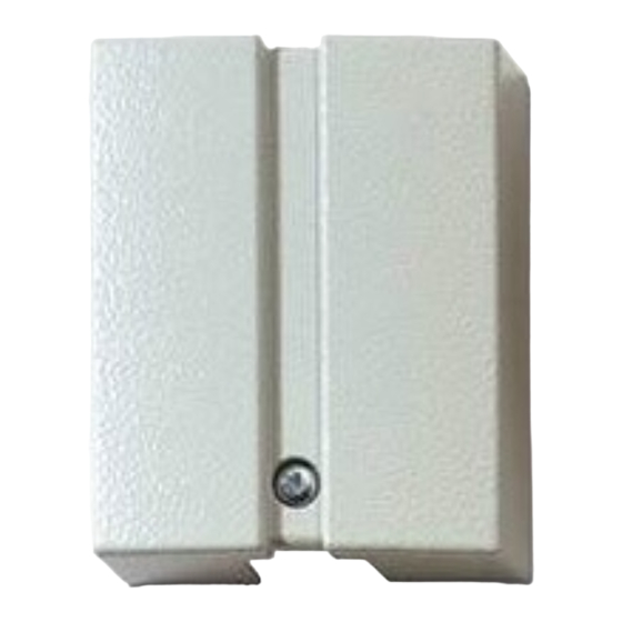
- Seite 3 Using the mounting plate VM600P as a EN: Installation Sheet template See Figure 1, item 14. General characteristics of the VV700 Setting up the detector Figure 1 (1) Cover (13) Area for mounting the VT705P See Figure 3. (2) Cover screw test transmitter (3) Steel clip (14) Mounting plate...
-
Seite 4: Specifications
• For the wiring diagram see the product label and/or manual Refer to the Plug-in board manual on how to activate supplied with the plug-in board. Remote test and Range test. Installing the SCM700 Detector verification The instructions for installing the SCM700 configuration See Figure 4. - Seite 5 Contact information Hvis der ikke er kommunikation, vælges <Setup> (punkt 8), <Communication> i menulinien, og indstillingerne af COM- www.utcfireandsecurity.com or www.interlogix.com porten opdateres. Vælg sprog og (om nødvendigt) en For customer support, see www.utcfssecurityproducts.eu godkendelsesstandard ved at vælge <Setup>, <Language/Approvals>.
- Seite 6 Programmering af VV700 Forbindelsesdiagrammet Se Figur 2. Figur 3: Forbindelsesdiagrammet (1) +12 VDC (10) Fejl udgang VV700 leveres uprogrammeret, og dette resulterer i et (2) 0 V (11) Advarsels udgang (programmerings) fejlsignal. (3) AUX (Ekstern ingang (12) Dag- / Nattilstand (Dag = tilbehør) Følg nedenstående programmeringsvejledning for at +12 VDC;...
- Seite 7 Programmierkabel mitgeliefert. Verwenden Sie das Kabel VVI740, um den Melder mit dem Kontaktinformation Laptop zu verbinden (Abbildung 3). www.utcfireandsecurity.com eller www.interlogix.com. Siehe Abbildung 2. For kundesupport se www.utcfssecurityproducts.dk Die „Kommunikations-Statusanzeige“ in der rechten unteren Bildschirmecke (Position 6) geht in grün über, sobald die...
-
Seite 8: Test-Betriebsarten
gegebenenfalls <Einsteckplatine> (Position 2) und Schaltbild <Empfindlichkeit> (Position 3) ein. Betätigen Sie <Download zum Melder> (Position 5), um den Melder zu programmieren. Abbildung 3: Schaltbild Nach erfolgreicher Beendigung des Downloads wird eine (1) +12 VDA (11) Voralarm-LED entsprechende Mitteilung ausgegeben. (2) 0 V (12) Scharf / Unscharf (Unscharf = (3) AUX (Zusatzeingang für... -
Seite 9: Es: Instrucciones De Instalación
VVI740. Kontaktinformationen Utilice el cable VVI740 para conectar el detector al PC (Figura ). www.utcfireandsecurity.com oder www.interlogix.com. Vea Figura 2. Kontaktinformationen für den Kundendienst finden Sie unter El indicador de Estado de la Comunicación que hay en la www.utcfssecurityproducts.de... -
Seite 10: Diagrama De Conexión
idioma y una norma de homologación (si es necesario), • Utilice <Analizar>, <Herramientas> para mediciones del funcionamiento in situ más detalladas. seleccione <Preparar>, <Idioma/Homologaciones>. Se guardarán entonces estos ajustes para uso futuro. Cableado del detector Configuración del VV700 Utilizar un cable de 6 hilos sin apantallar (WN106) o Vea Figura 2. - Seite 11 Ce programme fonctionne sous Windows 95, 98, NT, XP et Información de contacto 2000. Le programme de configuration SCM700 est fourni avec le câble de liaison VVI740. www.utcfireandsecurity.com o www.interlogix.com Utiliser le câble VVI740 pour la connexion avec l’ordinateur Para acceder al servicio técnico, consulte (figure 3).
-
Seite 12: Spécifications Techniques
Description des entrées et des sorties Configuration du VV700NF Voir figure 2. Figure 3: Entrées et sorties (10) LED de défaut (1) +12 VCC Le VV700 est fourni vierge de toute programmation, et en il en (11) LED d’ avertissement (2) 0 V résulte un signal de configuration en défaut. -
Seite 13: Informations Réglementaires
Contact Installazione del programma SCM700 www.utcfireandsecurity.com ou www.interlogix.com Le istruzioni per l’installazione del programma di Pour contacter l'assistance clientèle, voir configurazione SCM700 sul Vostro computer sono incluse nel www.utcfssecurityproducts.fr/mail_support.htm... - Seite 14 L’indicatore dello Stato di Comunicazione nell’angolo in basso • Per la conformità dell’apparecchio al II Livello della norma a destra (oggetto 6) diventa verde all’abilitazione della CEI 79-2, occorre installare il dispositivo di test VT705P, comunicazione tra laptop e rivelatore. Se la comunicazione è per la conformità...
-
Seite 15: Schema Collegamenti
Certificate da +5 a 40°C Dimensioni 100 x 80 x 33 mm Contatto per informazioni Colore Grigio RAL 7035 www.utcfireandsecurity.com o www.interlogix.com. Peso 395 g Per l'assistenza clienti, vedere www.utcfssecurityproducts.it Omologazione IMQ ALLARME II Livello con VT705P III Livello con VT705P, VT613P e VM695P... -
Seite 16: Nl: Installatie-Handleiding
genormeerde standaard te selecteren (indien vereist), NL: Installatie-handleiding selecteert u <Instellingen>, <Talen / Goedkeuringen>. Deze instellingen zullen bewaard blijven voor later gebruik. Algemene beschrijving van de VV700 Configuratie van de VV700 Figuur 1 Zie Figuur 3. (1) Deksel (14) Montageplaat De VV700 is bij levering niet geprogrammeerd, wat resulteert (2) Bevestigingsschroef deksel (15) Bevestigingsschroef... - Seite 17 Alarm lage / hoge www.recyclethis.info spanning −20 tot +55°C Bedrijfstemperatuur Contact informatie Afmetingen (H xB xD) 100 x 80 x 33 mm www.utcfireandsecurity.com of www.interlogix.com. Kleur Grijs RAL 7035 Voor klantenondersteuning, zie www.utcfssecurityproducts.nl Gewicht 395 g Tabel 1: Detectiebereik (m) Materiaal...
- Seite 18 Konfigurera VV700 SV: Installationmanual Se Figur 2. VV700 levereras oprogrammerad och detta leder till en Allmän beskrivning av VV700 felsignal (för konfigureringsfel). Programmera detektorn genom att följa nedanstående Figur 1 anvisningar för konfigurering. (1) Kåpa (16) Expanderskruv (2) Skruv för kåpa (17) Testsändare VT705P För att läsa in detektorns inställningar, välj <Configure>...
-
Seite 19: Teknisk Specifikation
Räckvidd Se Tabell 1 nedan Kontaktuppgifter Borrsköld, brytkontakt mot öppning och Skydd mot sabotage bräckning, spänning och / eller temperatur www.utcfireandsecurity.com eller www.interlogix.com Larm vid låg/hög Valbar (standard −15°C / +83°C) Kundsupport finns på www.utcfssecurityproducts.se temperatur Larm vid låg/hög Valbar (standard 8,5 V / 15,4 V) spänning... - Seite 20 P/N 1051965 (ML) • REV E • ISS 18APR19 20 / 20...


