Inhaltsverzeichnis
Werbung
Verfügbare Sprachen
Verfügbare Sprachen
Quicklinks
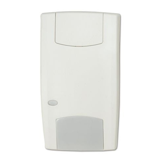
EV1012-D Series PIR Detector Installation Sheet
EN DE SV
1
3
© 2019 UTC Fire & Security Americas Corporation, Inc.
2
4
12 m range (39 ft. 4 in.)
8 m (26 ft. 2 in.)
6 m (19 ft. 8 in.)
4 m (13 ft. 1 in.)
2 m (6 ft. 6 in.)
0 m
2 m (6 ft. 6 in.)
4 m (13 ft. 1 in.)
6 m (19 ft. 8 in.)
8 m (26 ft. 2 in.)
2.4 m (7 ft. 10 in.)
(optimum)
P/N 146575999-1 (ML) • REV B • ISS 07MAR19
1 / 10
(1)
(3)
1
2.0 m
(39 ft. 4 in.)
(2)
Werbung
Inhaltsverzeichnis

Verwandte Anleitungen für Interlogix EV1012-D Serie


Inhaltszusammenfassung für Interlogix EV1012-D Serie
- Seite 1 EV1012-D Series PIR Detector Installation Sheet EN DE SV 12 m range (39 ft. 4 in.) 8 m (26 ft. 2 in.) 6 m (19 ft. 8 in.) 4 m (13 ft. 1 in.) 2 m (6 ft. 6 in.) 2 m (6 ft.
- Seite 2 EV1012-D EV1012AM-D (1) EV1012-D (1) EV1012AM-D J3 J4 J3 J4 < 33 Ω Normal larm < 33 Ω Normal larm (2) EV1012-D (2) EV1012AM-D J3 J4 J3 J4 J3 J4 J3 J4 J3 J4 J3 J4 Ω Normal 4.7 k Ω...
- Seite 3 J1: Not used EN: Installation Sheet J2: PIR enabling the LED On: Enables the detector LED at all times (default). Introduction Off: Puts the LED under control of the WT (walktest) input. If The EV1000-D series includes models EV1012-D and the WT input is connected to GND (terminal 1), the red LED EV1012AM-D.
-
Seite 4: Dip Switch Setting
If a PIR intruder alarm if detected in the Night mode and the PIR/AM Yellow Alarm To reset detector switches back to Day mode, the red LED starts relay relay flashing to indicate an alarm in memory. Low voltage Open Open Apply correct (Alarm) -
Seite 5: Contact Information
Verwenden Sie für Deckenmontagen, bei denen eine Contact information Überwachung von 90° erforderlich ist, den Befestigungssatz für Wand- und Deckenmontagen www.utcfireandsecurity.com or www.interlogix.com. (SB01). For customer support, see www.interlogix.com/customer- Schließen Sie die Abdeckung. support. Setzen Sie die Schraube und den kundenspezifischen Einsatz ein. DE: Installationsdatenblatt Verwenden Sie für Installationen gemäß... -
Seite 6: Dip-Schaltereinstellung
J5: Einstellung für D/N-Betrieb (Scharf/Unscharf) oder DIP-Schaltereinstellung Rtest (Ferntest) Verwenden Sie diese Steckbrücke, um Anschlussklemme 8 SW 1: Wann Abdeckungs(AM)- oder Technischer Fehler(TF)-Ausgabe signalisiert werden sollten entweder auf D/N oder Rtest einzustellen. UTC Fire & Security empfiehlt für die erforderliche Verwaltung der AM/TF- Ein: Signalisiert AM oder TF nur, wenn sich das System im Aktivierung die Einstellung D/N. -
Seite 7: Rechtliche Hinweise
1,8 m bis 3,0 m Kontaktinformation Erfassungsgeschwindigkeits- 30 cm/s bis 20 cm/s bis 3 m/s bereich 3 m/s www.utcfireandsecurity.com oder www.interlogix.com Eigenschaften Alarmrelais (NC) 80 mA 80 mA Kontaktinformationen für den Kundendienst finden Sie auf / Sabotagerelais 30 V , resistiv 30 V www.interlogix.com/customer-support... - Seite 8 J1 : Används ej Installationsanvisningar Tekniken som används i de här detektorerna är gjord för att J2 : PIR-aktivering av LED:en undvika falsklarm. Undvik dock potentiella orsaker till På: Detektorns LED är hela tiden aktiverad (standard). instabilitet såsom (se bild 1): Av: Gör det möjligt att styra LED:en via WT-ingången •...
- Seite 9 Om ett PIR-inkräktarlarm detekteras i nattläget och detektorn Gul LED Larmrelä AM- Återställning Röd PIR/AM kopplas om till dagsläge, börjar den röda LED:en blinka för att relä indikera att det finns ett larm i minnet. Uppstart Sluten Sluten Automatiskt efter 60 s Larmminnet återställs genom att detektorn kopplas om till nattläge.
- Seite 10 återförsäljare vid köp av liknande ny utrustning eller lämnas till en därför avsedd deponering. För mer information, se: www.utcfssecurityproducts.eu/recycle/ Kontaktuppgifter www.utcfireandsecurity.com eller www.interlogix.com Kundsupport finns på www.interlogix.com/customer-support. P/N 146575999-1 (ML) • REV B • ISS 07MAR19 10 / 10...