Inhaltsverzeichnis
Werbung
Verfügbare Sprachen
Verfügbare Sprachen
Quicklinks
ISTRUZIONI PER L'INSTALLAZIONE E LA MANUTENZIONE
Gentile Cliente,
metta in funzione la sua nuova caldaia entro 30gg dalla data di installazione da personale
professionalmente qualificato. Potrà così beneficiare sia della garanzia legale, sia della
garanzia convenzionale Sime che trova alla fine di questo manuale.
Fonderie SIME S.p.A
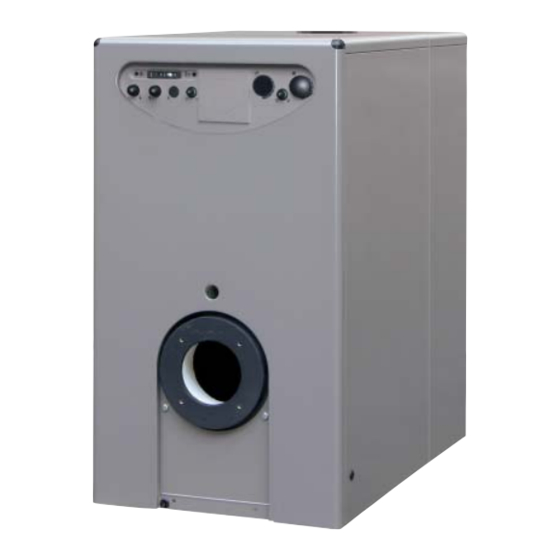
Estelle HE
FR
IT
RUS
BE
ES
GR
PT
ENG
SL
Cod. 6276070B - 10/2015
DE
RO
Werbung
Kapitel
Inhaltsverzeichnis

Verwandte Anleitungen für Sime Estelle HE-Serie


Inhaltszusammenfassung für Sime Estelle HE-Serie
-
Seite 66: Epi°Paºh Toy §Ebhta
¶EPI°PAºH TOY §EBHTA EI™A°ø°H ÌÂÏÂÙ‹ıËÎ·Ó Û‡Ìʈӷ Ì ٷ ¶ÚfiÙ˘· Ù¤ÏÂÈ· ÈÛÔÚÚÔË-̤ÓË Î·‡ÛË Ì ˘„ËϤ˜ ∞Ô‰fiÛÂˆÓ Ù˘ ∂√∫ 92/42. ıÂÚÌÈΤ˜ ·Ô‰fiÛÂȘ ÁÈ· ÔÈÎÔÓÔÌÈ΋ ÏÂÈÙÔ˘ÚÁ›·. √È ¯˘ÙÔÛȉËÚÔ› Ϥ‚ËÙ˜ «ESTELLE HE» §ÂÈÙÔ˘ÚÁÔ‡Ó Ì ÂÙÚ¤-Ï·ÈÔ Î·È ¤¯Ô˘Ó ÌÈ· ¢IA™TA™EI™ ( ™¯. 1) Estelle HE 4 HE 5 M‹ÎÔ˜... -
Seite 67: Texnika Xapakthpi™Tika
TEXNIKA XAPAKTHPI™TIKA ESTELLE HE 4 HE 5 £ÂÚÌÈ΋ ÈÛ¯‡˜ 80-60 Ô 28,8 38,8 50-30 Ô 30,3 40,8 IÛ¯‡˜ ÂÛÙ›·˜ 30,0 40,0 ∆¿ÍË ·fi‰ÔÛ˘ (∂√∫ 92/42) AÚÈıÌfi˜ ÛÙÔȯ›ˆÓ M¤ÁÈÛÙË ›ÂÛË ¶ÂÚÈÂÎÙÈÎfiÙËÙ· ÓÂÚÔ‡ 16,8 20,8 AÒÏÂÈ· ÊÔÚÙ›Ô˘ η˘Û·ÂÚ›ˆÓ mbar 0,13 0,21 ¢Ú ÓÂÚÔ‡ (¢t 10 C Ô... -
Seite 68: Ia°Pamma §Eitoyp°Ia
¢IA°PAMMA §EITOYP°IA™ ( ™¯. 2/a) ¶∂ƒπ∂Ã√ª∂¡√ ‚ËÙ·˜ ÓÔÍ› ‰ ˆÙÔ ¯¿Ï˘‚· Û˘Ì˘ÎÓˆÙ‹ 3 ™È Ê fiÓÈ ‰È · ÚÚÔ‹ ¶ÚÔÛ·ÁˆÁ‹ EÈÛÙÚÔÊ‹ ™¯. 2/a £A§AMO™ KAY™H™ √ ı¿Ï·ÌÔ˜ η‡Û˘ Â›Ó·È ÙÔ˘ Ù‡Ô˘ Ì ¿ÌÂÛÔ ¤Ú·ÛÌ· Î·È Â›Ó·È Û‡Ìʈ-ÓÔ Ì ÙËÓ ÚԉȷÁÚ·Ê‹ EN 303-3 Û˘ÓËÌ̤ÓÔ ∂. √È ‰È·ÛÙ¿ÛÂȘ... -
Seite 69: Àª¶À∫¡Fl¡∂Π ∆∏™ ∂∫ºÿƒ∆Ø
1.7.3 TÔÔı¤ÙËÛË ÙÔ˘ η˘ÛÙ‹Ú· H fiÚÙ· ÙÔ˘ Ϥ‚ËÙ· Â›Ó·È Î·Ù¿ÏÏËÏË ÁÈ· ÙËÓ ÙÔÔı¤ÙËÛË Î·˘ÛÙ‹Ú· (Û¯ 3/a). OÈ Î·˘ÛÙ‹Ú˜ Ú¤ÂÈ Ó· Â›Ó·È Ú˘ıÌÈṲ̂ÓÔÈ ¤ÙÛÈ ÒÛÙÂ Ë ÙÈÌ‹ ÙÔ˘ CO2 Ó· Â›Ó·È ÂΛÓË Ô˘ ·Ó·Ê¤ÚÂÙ·È ÛÙÔ ÛËÌÂ›Ô 1.3 Ì ·ÓÔ¯¤˜ ± 5%. 1 1 1 1 . -
Seite 70: Ebhto™Ta™Io
ÁÂȈ̤ÓË ÂÁηٿÛÙ·ÛË. Ù˘ ÂÁηٿÛÙ·Û˘ ı· Ú¤ÂÈ Ó· ·ÓÙÈÛÙÔȯ› οıÂÙÔ˜ Î·È ÙÔ ÙÂÚÌ·ÙÈÎfi ̤ÚÔ˜ Ú¤ÂÈ ÙÔ˘Ï¿¯ÈÛÙÔÓ ÛÙËÓ ÂÏ¿¯ÈÛÙË ÙÈÌ‹ 0,5 bar). Ó· ¤¯ÂÈ ¤Ó· ÛÙ·ÙÈÎfi ·ÔÚ-ÚÔÊËÙ‹Ú· Ô˘ H SIME ·ÔÔÈÂ›Ù·È Î¿ı ¢ı‡Ó˘ ‰È·ÛÊ·Ï›˙ÂÈ ÌÈ· ÛÙ·ıÂÚ‹ ÂÎΤӈÛË ÙˆÓ ˙ËÌÈÒÓ Û ˘ÏÈο ‹... - Seite 71 ¶PO™OXH: To ηʤ ηÏÒ‰Èo (ÌovˆÌ¤vo) xpËÛÈÌooÈÂ›Ù·È ·oÎÏÂÈÛÙÈο ÁÈ· ÙË Û‡v‰ÂÛË Ùˆv η˘ÛÙ‹pˆv Ì ÌfivÈÌË ÙpoÊo‰oÛ›· (Ù‡o˜ B1). ¶EPIEXOMENO °Ú·ÌÌ‹ TA £ÂÚÌÔÛÙ¿Ù˘ ¯ÒÚÔ˘ Ou‰¤ÙÂÚo OP XÚovo‰È·ÎfiÙ˘ ÚoÁÚ·ÌÌ·ÙÈÛÌÔ‡ °ÂÓÈÎfi˜ ‰È·ÎfiÙ˘ (Úo·ÈÚÂÙÈο) TS £ÂÚÌÔÛÙ¿Ù˘ ·ÛÊ·Ï›·˜ TC £ÂÚÌÔÛÙ¿Ù˘ Ϥ‚ËÙ· ™∏ª∂πø™∏: SA ¶Ú¿ÛÈÓÔ˘ led ·ÚouÛ›·˜ Ù¿Û˘ - ™˘Ó‰¤ovÙ·˜...
-
Seite 72: Xph™H Kai ™Ynthph™H
XPH™H KAI ™YNTHPH™H E§E°XO™ ¶PIN TH - µÂ‚·Èˆı›Ù fiÙÈ ÙÔ «¶ÈÛÙÔÔÈËÙÈÎfi ˙ËÙ‹ÛÙ ÙËÓ Â¤Ì‚·ÛË Ù˘ ∂ÍÔ˘ÛÈÔ- §EITOYP°IA ‰ÔÎÈÌ‹˜» ‰ÂÓ Â›Ó·È Ì¤Û· ÛÙÔ ı¿Ï·ÌÔ ‰ÔÙË̤Ó˘ ∆¯ÓÈ΋˜ ÀÔÛÙ‹ÚÈ͢ ÁÈ· η‡Û˘. ¤Ó·Ó ¤ÏÂÁ¯Ô. ¶ÚÈÓ Ú·ÁÌ·ÙÔÔÈËı› ÙÔ ÚÒÙÔ ÍÂΛÓËÌ· - ∆ÚÔÊÔ‰ÔÙ›ÛÙ ٿÛË ÛÙÔ Ï¤‚ËÙ· ÙÔ˘... - Seite 73 RONDO' 3/4 OF ESTELLE 3/4 OF ESTELLE HE 4 RONDO' 5/6 OF ESTELLE 5/6 OF ESTELLE HE 5 ™¯. 8 E¶OXIAKO™ ÛÙÂÚˆ̤ÓÔ˜ ÛÙ· ÏÂ˘Ú¿ Ì ·ÛÊ¿ÏÂȘ Â›Ó·È Î·ÓÔÓÈ΋, ·Ó ı¤ÏÔ˘Ó ÂÍ·ÂÚÈÛÌfi ÔÈ KA£API™MO™ Û‡Ó‰ÂÛ˘; ÛˆÏËÓÒÛÂȘ ÙÚÔÊÔ‰ÔÛ›·˜ η˘Û›-ÌÔ˘, - •ÂÌÔÓÙ¿ÚÂÙ ÙÔÓ ›Ó·Î· ÂϤÁ¯Ô˘ (9) ÙËÓ...
-
Seite 74: Anti¶A°Øtikh ¶Po™Ta™Ia
ÙˆÓ Î·ÓÒÓ, ÂӉ¯fi-ÌÂÓ˜ ‰È·ÚÚÔ¤˜ Ú‡ıÌÈÛË Ù˘ ›‰È·˜ Ù˘ ‚·Ï‚›‰·˜. ·fi ÙÔÓ ÂÓ·ÏÏ¿ÎÙË ÙÔ˘ boiler. ÙÔ˘ Ϥ‚ËÙ· ‹ ÙÔ˘ ‰ÈÎÙ‡Ô˘ ÂÎΤӈÛ˘ (ÔÚÙ¿ÎÈ, ı¿Ï·ÌÔ˜ η‡Û˘, ‰›ÎÙ˘Ô ÂÎΤӈ-Û˘ ηÓÒÓ, ηÓÔ‰fi¯Ô, ÊÏ¿Ó- ANTI¶A°øTIKH XPH™IME™ ¶§HPOºOPIE™ Ù˙˜). ¶PO™TA™IA °IA TON KATANA§øTH - ∂ϤÁÍÙ ÙËÓ ÔÈfiÙËÙ· ÙˆÓ Î·˘-ۛ̈Ó. ™Â... - Seite 85 Die FONDERIE SIME S.p.A. mit Sitz in Via Garbo 27 - Legnago (VR) - Italy erklärt, dass ihre Gasöl-Heizkessel in Übe- reinstimmung mit Artikel 3 Absatz 3 der PED-Richtlinie EWG 97/23 hergestellt werden, lt. einem korrekten Kon- struktionsverfahren, da entworfen und erzeugt nach UNI EN 303 -1: 2002.
-
Seite 86: Einleitung
BESCHRIJVING VAN DE KETEL 1. 1 EINLEITUNG rungswirkungsgrad EWG 92/42. Sie ver- beträchtliche Ersparnis an Brennstof f brennen leichtes Heizöl, haben eine perfekt ermöglicht. Die Gusseisen-Brennwertkessel “ESTELLE ausgeglichene Verbrennung und einen sehr HE” entsprechen der Richtlinie zum Feue- hohen Feuerungswirkungsgrad, was eine AUSSENABMESSUNGEN (Abb. -
Seite 87: Technische Merkmale
TECHNISCHE MERKMALE ESTELLE HE 4 HE 5 Nutzleistung 80-60°C 28,8 38,8 50-30°C 30,3 40,8 Wärmeabgabe 30,0 40,0 Effizienz-Klasse (EWG 92/42) Elemente n° Maximaler Betriebsdruck Fassungsvermögen Wasser 16,8 20,8 Druckverlust Rauchgasseite mbar 0, 1 3 0,21 Druckverlust Wasserseite (∆t 10°C) mbar Druck Verbrennungskammer mbar –0,02... -
Seite 88: Wasserkreislauf
Estelle HE 4 G 0S - LX TXC DANFOSS 0,60 45°H 12,0 Estelle HE 5 G 1S - LX TC DANFOSS 0,75 45°H 13,5 1.7.2 Brenner “SIME” Modell Düse Zerstäubungs- Pumpe-druk Tipo ø winkel Estelle HE 4 MACK 4 DELEVAN 0,75 60°W... -
Seite 89: Kondensatablass Connection
1.7.3 Montage des Brenners (Abb. 3/a) Die Kesseltür ist bereits für die Montage des Brenners vorbereitet (Abb. 3/a). Die Brenner müssen so geregelt werden, dass das CO mit dem Wer t überein- stimmt, der in Punkt 1.3 angegeben ist, wobei eine Toleranz von ± 5% möglich ist. KONDENSATABLASS CONNECTION (Abb. -
Seite 90: Heizraum
INSTALLATIE 2. 1 HEIZRAUM – Häufige Wasserzufuhr; Integration von nungsgase, muss die Öf fnung des Anlagen. Abfuhrkanals mindestens 0,4 m über Der Heizraum muss allen Anforderungen – Wenn die Anlage zur Gänze oder teilwei- jeder anderen Anlage liegen, die weniger und Normen für Heizungsanlagen entspre- se entleert werden muss. - Seite 91 ACHTUNG: Das braune Kabel (isoliert) wird ausschließlich zum Anschluss von Brennern mit Dauerspeisung (Typ B1) verwendet. LEGENDE B1 Brenner mit Dauerspeisung (nicht im Lieferumfang) Leitung Raumthermostat Neutral Zeituhr (Option) Hauptschalter Sicherheitsaquastat HINWEIS: Kesselaquastat - Wenn Sie einen Raumthermostat (TA) montieren, müs- Grüne Led Spannungsmessung sen Sie die Überbrückung von Klemme 4 - 5 entfernen.
-
Seite 92: Gebrauchsanweisung Und Wartung
GEBRAUCHSANWEISUNG UND WARTUNG 3. 1 KONTROLLEN VOR DER – setzen Sie den Kessel mit dem Haupt- Hydrometer bei kalter Anlage Druckwerte INBETRIEBNAHME schalter (1) unter Spannung, das Ein- zwischen 1 und 1,2 bar aufweist. Wenn der DES KESSELS schalten der grünen Led (3) gestattet Druck unter 1 bar liegt, müssen Sie das es, zu überprüfen, ob Spannung am beheben. - Seite 93 RONDO' 3/4 OF ESTELLE HE 4 ESTELLE 3/4 OF RONDO' 5/6 OF ESTELLE HE 5 ESTELLE 5/6 OF Abb. 8 3.3. 1 Rauchgasseite (4) auf dieselbe Weise. lung der Luft und die Funktion des Bren- des Kessels (Abb. 8) nerautomaten. Zur Reinigung der Rauchgasdurchlässe 3.3.4 Funktionsstörungen...
-
Seite 94: Frostsicherung
nungsgemäß funktioniert. dass die Heizanlage in Betrieb bleibt und Funktion des Geräts müssen Sie das Gerät dass die Räumlichkeiten sowie der Ort, an ausschalten. Versuchen Sie nicht, das Das Sicherheitsventil des Kessels wird dem der Kessel installiert ist, ausreichend Gerät selbst zu reparieren. oft ausgelöst.