Herunterladen Inhalt Inhalt Diese Seite drucken
Inhaltsverzeichnis

Werbung

Verfügbare Sprachen
  • DE

Verfügbare Sprachen

  • DEUTSCH, seite 63
Estelle HE 3-4-5-6-7 ErP
ISTRUZIONI PER L'INSTALLAZIONE E LA MANUTENZIONE
Gentile Cliente,
metta in funzione la sua nuova caldaia entro 30gg dalla data di installazione da personale
professionalmente qualificato. Potrà così beneficiare sia della garanzia legale, sia della
garanzia convenzionale Sime che trova alla fine di questo manuale.
Fonderie SIME S.p.A
FR
IT
NL
ES
DE
GR
ENG
SL
Cod. 6276059 - 03/2017

Werbung

Inhaltsverzeichnis
loading

Inhaltszusammenfassung für Sime Estelle HE 3 ErP

  • Seite 1 30gg dalla data di installazione da personale professionalmente qualificato. Potrà così beneficiare sia della garanzia legale, sia della garanzia convenzionale Sime che trova alla fine di questo manuale. Fonderie SIME S.p.A Cod. 6276059 - 03/2017...
  • Seite 2: Inhaltsverzeichnis

    INDICE DESCRIZIONE DELL’APPARECCHIO INTRODUZIONE ............................... DIMENSIONI DATI TECNICI ................................PERDITE DI CARICO CIRCUITO CALDAIA SCHEMA FUNZIONALE ............................CAMERA DI COMBUSTIONE BRUCIATORI ABBINABILI ALLACCIAMENTO SCARICO CONDENSA ....................... INSTALLAZIONE LOCALE CALDAIA ..............................DIMENSIONI LOCALE CALDAIA ALLACCIAMENTO IMPIANTO ALLACCIAMENTO ALLA CANNA FUMARIA ALLACCIAMENTO ELETTRICO USO E MANUTENZIONE CONTROLLI PRELIMINARI ALL’ACCENSIONE .......................
  • Seite 3: Descrizione Dell'apparecchio

    DESCRIZIONE DELL’ APPARECCHIO INTRODUZIONE LE HE ErP fun zio na no a ga so lio con una za re co spi cui ri spar mi nei co sti di eser ci zio. com bu stio ne per fet ta men te equi li bra ta e Le cal daie di ghi sa a condensazione ESTEL­...
  • Seite 4: Dati Tecnici

    30÷85 30÷85 Peso PERDITE DI CARICO CIRCUITO CALDAIA (fig. 2) ESTELLE HE 7 ErP ESTELLE HE 6 ErP ESTELLE HE 5 ErP ESTELLE HE 4 ErP ESTELLE HE 3 ErP 1000 2000 3000 4000 5000 6000 Portata (l/h) Fig. 2...
  • Seite 5: Schema Funzionale

    La camera combustione è del tipo a pas- saggio diretto ed è conforme alla norma EN 303-3 allegato E. Le dimensioni della camera di combustione sono riportate in fig. 3. Volume Estelle HE 3 ErP 17,5 Estelle HE 4 ErP 24,0 Estelle HE 5 ErP 30,5...
  • Seite 6: Allacciamento Scarico Condensa

    1.7.2 Montaggio del bruciatore (fig. 3/a) La porta della caldaia è predisposta per il montaggio del bruciatore (fig. 3/a). I bruciatori devono essere regolati in modo tale che il valore della CO 2 sia quello indi- cato al punto 1.3 con tolleranze ± 5%. ALLACCIAMENTO SCARICO CONDENSA (fig.
  • Seite 7: Installazione

    INSTALLAZIONE LO CA LE CAL DAIA – Im pian ti mol to este si (con ele va ti con te- re una aspi ra to re sta ti co che as si cu ra nu ti d’ac qua). una ef fi cien te e co stan te eva cua zio ne dei Il lo ca le cal daia de ve pos se de re tut ti i re- –...
  • Seite 8 ATTENZIONE: Il cavo colore mar­ rone (isolato) si utilizza esclusiva­ mente per il collegamento di bru­ ciatori con alimentazione perma­ nente (tipo B1). LE GEN DA Linea Neutro In ter rut to re principale Ter mo sta to si cu rez za Ter mo sta to cal daia Led verde presenza tensione Pom pa im pian to...
  • Seite 9: Uso E Manutenzione

    USO E MANUTENZIONE AVVERTENZE – In caso di guasto e/o cattivo funzionamento dell’apparecchio, disattivarlo, astenen­ dosi da qualsiasi tentativo di riparazione o d’intervento diretto. Rivolgersi esclusiva­ mente a personale qualificato. – Per motivi di sicurezza l’Utente non può accedere a parti interne dell’apparecchio. Tutte le operazioni che prevedono la rimozione di protezioni o comunque l’accesso a parti pericolose dell’apparecchio devono essere eseguite da personale qualificato.
  • Seite 10: Riempimento Impianto

    ESTELLE RONDO' 3/4 OF HE 3­4 ErP ESTELLE 3/4 OF ESTELLE RONDO' 5/6 OF HE 5­6 ErP ESTELLE 5/6 OF Fig. 8 3.2.3 Riempimento impianto tubo evacuazione fumi rimuovendo i resi- sblocco; fatto ciò, se avviene un’accensione dui. A manutenzione avvenuta, nei modelli regolare, si può...
  • Seite 11: Protezione Antigelo

    preregolata, il corretto funzionamento e PROTEZIONE ANTIGELO DISINSTALLAZIONE, posizionamento del termostato di rego- SMALTIMENTO E RECICLAGGIO lazione. In caso di gelo assicurarsi che l’impianto di DELL’APPARECCHIO – Assicurarsi che il generatore sia di po- riscaldamento rimanga in funzione e che i tenza sufficiente per l’impianto.
  • Seite 12: Garanzia Convenzionale

    5 anni dalla data di messa in commercio •l’Utente dovrà conservare la propria copia, da esibire al dell’apparecchio. Fonderie SIME SpA si riserva di variare in qualunque momento e senza preavviso i propri prodotti nell’intento di migliorarli senza pregiudicarne le caratteristiche essenziali.
  • Seite 13 INDICE DESCRIPCION DE LA CALDERA 1.1 INTRODUCCION .............................. 14 1.2 DIMENSIONES 1.3 DATOS TECNICOS .............................. 15 1.4 PERDIDAS DE CARGA 1.5 ESQUEMA DE FUNCIONAMIENTO .......................... 16 1.6 CAMARA DE COMBUSTION 1.7 QUEMADORES ACOPLABLES 1.8 CONEXION DESCARGA CONDENSACION ...................... 17 INSTALACION 2.1 CUARTO CALDERA .............................. 18 2.2 DIMENSIONES CUARTO CALDERA 2.3 CONEXION DE LA INSTALACION 2.4 CONEXION A LA CHIMENEA 2.5 CONEXION ELECTRICA USO Y MANTENIMIENTO 3.1 CONTROLES PREVIOS A LA PUESTA EN MARCHA .................... 20 3.2 ENCENDIDO Y FUNCIONAMIENTO...
  • Seite 14: Descripcion De La Caldera

    DESCRIPCION DE LA CALDERA 1.1 INTRODUCCION densación ESTELLE HE ErP funcionan rendimientos permiten conseguir impor- con gasóleo, con una combustión per- tantes ahorros de combustible. Las calderas de hierro fundido de con- fectamente equilibrada y los muy altos 1.2 DI M EN S IO N I (fig. 1) Estelle HE 3 ErP 4 ErP 5 ErP 6 ErP 7 ErP...
  • Seite 15 1.3 DATOS TECNICOS ESTELLE HE 3 ErP 4 ErP 5 ErP 6 ErP 7 ErP Potencia térmica 80-60°C 25,5 33,0 40,0 48,0 59,7 50-30°C 26,7 35,5 42,2 50,5 62,8 Caudal térmico 26,2 34,8 41,0 49,0 61,0 Clase de eficiencia energética estacional de calefacción Eficiencia energética estacional de calefacción 97,0 94,0 93,0 93,0 93,0 Número PIN 1312CR193R 1312CR193R 1312CR193R 1312CR193R 1312CR193R Tipo B23P B23P...
  • Seite 16: Camara De Combustion

    Fig. 3 caldera ha sido probada. 1.7.1 Quemadores alimentación permanente Modelo Código Inyector Angle Presión Clase Potencia eléctrica Tipo ø bomba NOx absorbida pulverización bar Estelle HE 3 ErP SIME MACK 3 8099000 DELAVAN 0,55 60°S 12,5 Estelle HE 4 ErP SIME MACK 4 8099010 DELAVAN 0,75 60°W 11,0 Estelle HE 5 ErP SIME MACK 5 8099030 DELAVAN 0,85 60°W 13,0...
  • Seite 17 1.7.2 Montaje de los quemadores (fig. 3/a) La puerta de la caldera se suministra predispuesta para el montaje del que- mador (fig. 3/a). Los quemadores deben ser regulados de modo tal que el valor de la CO sea el indicado en el punto 1.3 con una tolerancia de ± 5%. 1.8 CONEXIÓN DESCARGA CONDENSACIÓN (fig. 4) Para recoger la condensación es nece- sario conectar el goterón con sifón a la descarga, mediante un tubo (ø 25) que tiene una pendiente mínima de 5 mm por metro.
  • Seite 18: Dimensiones Cuarto Caldera

    INSTALACION 2.1 CUARTO CALDERA calefacción debe tratarse en conformi- salida de los gases, esté por encima de dad con la Norma UN-CTI 8065. En los cualquier lomera adyacente, de unos El cuarto caldera debe poseer todos siguientes casos, es totalmente indispen- 0,4 m y alejada, menos de 8 m; los requisitos de las normas para las sable el tratamiento del agua utilizada por – el conducto de la chimenea debe tener instalaciones térmicas a combustibles la instalación de calefacción: un diámetro no inferior, al del racor de...
  • Seite 19 ATENCIÓN: El cable de color marrón (aislado) se utiliza exclusivamente para la conexión de quemadores con alimentación permanente (tipo B1). LEYEN D A Línea Neutro Interruptor general TS Ter m ó s ta t o de seguridad TC Ter m ó s ta t o cal d era SA Led presencia tensión Bomba instalación Quemador alimentación directa (no incluido) opcional B1 Quemador alimentación permanente ( opcional B2 Quemador alimentación permanente de dos etapas ( TA Ter m ó s ta t o am b ien t e...
  • Seite 20: Uso Y Mantenimiento

    USO Y MANTENIMIENTO ADVERTENCIAS – Desactivar el equipo en caso de rotura y/o mal funcionamiento, absteniéndose de realizar cualquier intento de reparación o de intervención directa. Para esto dirigirse exclusivamente a personale técnico autorizado. – Por motivos de seguridad, el usuario no puede acceder a las partes internas del apa- rato. Todas las operaciones que prevén el desmontaje de protecciones o el acceso a las partes peligrosas, debe ser llevadas a cabo por personal cualificado. – El aparato puede ser utilizado por niños mayores de 8 años y por personas con capa- cidades físicas, sensoriales o mentales reducidas, o sin la experiencia o los conoci- mientos necesarios, siempre y cuando estén vigilados por una persona responsable, o bien si previamente han sido informados sobre cómo utilizar de forma segura el aparato y han comprendido los peligros relacionados con el mismo. Los niños no de- ben jugar con el aparato. Las operaciones de limpieza y mantenimiento destinadas que deben ser realizadas por el usuario no deben ser efectuadas por niños sin la vigilancia de un adulto responsable. 3.1 CONTROLES PREVIOS – colocar el mando del termóstato cal- me manual (2) interviene, provocando el A LA PUESTA EN MARCHA dera (5) a una temperatura de mínimo...
  • Seite 21: Limpieza Estacional

    ESTELLE HE RONDO' 3/4 OF 3-4 ErP ESTELLE 3/4 OF ESTELLE HE RONDO' 5/6 OF 5-6 ErP ESTELLE 5/6 OF Fig. 8 3.2.3 Rellenado de la instalación modelos ESTELLE HE 3-4-5-6 ErP, colo- pués de haber presionado a fondo el car los turbuladores en la posición inicial. pulsador de desbloqueo; hecho esto, Controlar periódicamente que, con la Las operaciones de manunteción se reali- se produce un encendido regular, se instalación fría, el hidrómetro tenga zan sin quitar el quemador.
  • Seite 22: Proteccion Antihielo

    las prestaciones del quemador, la la válvula misma. exclusivamente al personal autorizado temperatura preregulada, el correcto de la zona. funcionamiento y ubicación del ter- móstato de regulación. 3.4 PROTECCION ANTIHIELO – Asegúrarse que el generador sea de 3.6 ELIMINACIÓN DEL APARATO potencia suficiente para la instalación. En caso de hielo asegúrese que la insta- (DIRECTIVA EUROPEA lación de calefacción quede en funcio- 2002/96/CE) Olor de productos no incombustible namiento y que los locales, como así...
  • Seite 23 ΠΕΡΙΕΧΟΜΕΝΑ ΠΕΡΙΓΡΑΦΗ ΤΗΣ ΣΥΣΚΕΥΗΣ ΕΙΣΑΓΩΓΗ ..........................................ΔΙΑΣΤΑΣΕΙΣ ΤΕΧΝΙΚΑ ΣΤΟΙΧΕΙΑ ........................................ ΑΠΩΛΕΙΕΣ ΦΟΡΤΙΟΥ ΚΥΚΛΩΜΑΤΟΣ ΛΕΒΗΤΑ ΛΕΙΤΟΥΡΓΙΚΟ ΔΙΑΓΡΑΜΜΑ ....................................ΘΑΛΑΜΟΣ ΚΑΥΣΗΣ ΚΑΥΣΤΗΡΕΣ ΠΟΥ ΜΠΟΡΟΥΝ ΝΑ ΣΥΝΔΥΑΣΤΟΥΝ ΣΥΝΔΕΣΗ ΕΚΚΕΝΩΣΗΣ ΝΕΡΟΥ ΣΥΜΠΥΚΝΩΣΗΣ ............................ ΕΓΚΑΤΑΣΤΑΣΗ ΔΩΜΑΤΙΟ ΛΕΒΗΤΑ ........................................ ΔΙΑΣΤΑΣΕΙΣ ΔΩΜΑΤΙΟΥ ΛΕΒΗΤΑ ΣΥΝΔΕΣΗ ΣΥΣΤΗΜΑΤΟΣ ΣΥΝΔΕΣΗ ΜΕ ΤΟ ΣΩΛΗΝΑ ΚΑΠΝΟΔΟΧΟΥ ΗΛΕΚΤΡΙΚΗ...
  • Seite 24: Περιγραφη Τησ Συσκευησ

    ΠΕΡΙΓΡΑΦΗ ΤΗΣ ΣΥΣΚΕΥΗΣ ΕΙΣΑΓΩΓΗ ESTELLE HE ErP λειτουργούν με πετρέλαιο μηση του κόστους λειτουργίας. ντίζελ με μια εξαιρετικά ισορροπημένη καύση Οι λέβητες χυτοσιδήρου συμπύκνωσης και η υψηλή απόδοση επιτρέπει την εξοικονό- ΔΙΑΣΤΑΣΕΙΣ (εικ. 1) Estelle HE 3 ErP 4 ErP 5 ErP 6 ErP 7 ErP...
  • Seite 25: Τεχνικα Στοιχεια

    30÷85 30÷85 30÷85 Βάρος ΑΠΩΛΕΙΕΣ ΦΟΡΤΙΟΥ ΚΥΚΛΩΜΑΤΟΣ ΛΕΒΗΤΑ (εικ. 2) ESTELLE HE 7 ErP ESTELLE HE 6 ErP ESTELLE HE 5 ErP ESTELLE HE 4 ErP ESTELLE HE 3 ErP 1000 2000 3000 4000 5000 6000 Portata (l/h) Εικ. 2...
  • Seite 26: Λειτουργικο Διαγραμμα

    Ο θάλαμος καύσης είναι τύπου άμεσου περά- σματος και συμμορφώνεται με το πρότυπο EN 303-3 συνημμένο E. Οι διαστάσεις του θαλάμου καύσης αναφέρο- νται στην εικ. 3. Όγκος Estelle HE 3 ErP 17,5 Estelle HE 4 ErP 24,0 Estelle HE 5 ErP 30,5...
  • Seite 27 Καυστήρες σταθερής τροφοδοσίας Μοντέλο Κωδικός Αρκοφύσιο Γωνία Πίεση Κατηγορία Ηλεκτρικής ισχύς Τύπος ø αντλίας που απορροφάται κονιορτοποίηση Estelle HE 3 ErP SIME MACK 3 8099000 DELAVAN 0,55 60°S 12,5 Estelle HE 4 ErP SIME MACK 4 8099010 DELAVAN 0,75 60°W...
  • Seite 28: Εγκατασταση

    ΕΓΚΑΤΑΣΤΑΣΗ ΔΩΜΑΤΙΟ ΛΕΒΗΤΑ απαραίτητη η επεξεργασία του νερού στις της κορυφογραμμής της σκεπής) σε από- εξής περιπτώσεις: σταση λιγότερο από 8 m. Ο χώρος του λέβητα πρέπει να πληροί όλες τις – Πολύ εκτεταμένες εγκαταστάσεις (με υψη- – Η καπνοδόχος πρέπει να έχει διάμετρο όχι απαιτήσεις...
  • Seite 29 ΠΡΟΣΟΧΗ: Το καλώδιο χρώματος καφέ (μονωμένο) χρησιμοποιείται μόνο για τη σύνδεση των καυστήρων μόνιμης τροφοδοσίας (τύπος Β1). ΥΠΟΜΝΗΜΑ Γραμμή Ουδέτερο Κύριος διακόπτης Θερμοστάτης ασφαλείας Θερμοστάτης λέβητα Led πράσινο παρουσίας τάσης Αντλία εγκατάστασης Καυστήρας άμεσης τροφοδοσίας (δεν παρέχεται) Καυστήρες μόνιμης τροφοδοσίας (Προαιρετικό) Καυστήρες...
  • Seite 30: Χρηση Και Συντηρηση

    ΧΡΗΣΗ ΚΑΙ ΣΥΝΤΗΡΗΣΗ ΠΡΟΕΙΔΟΠΟΙΗΣΕΙΣ – Σε περίπτωση βλάβης ή/και δυσλειτουργίας της συσκευής, απενεργοποιείστε τη και μην επιχειρήσετε να την επισκευάσετε ή να παρέμβετε άμεσα. Επικοινωνήστε μόνο με εξειδικευμένο τεχνικό προσωπικό. – Για λόγους ασφαλείας, ο χρήστης δεν μπορεί να έχει πρόσβαση στα εσωτερικά εξαρτή- ματα.
  • Seite 31: Εποχιακοσ Καθαρισμοσ

    ESTELLE RONDO' 3/4 OF HE 3-4 ErP ESTELLE 3/4 OF ESTELLE RONDO' 5/6 OF HE 5-6 ErP ESTELLE 5/6 OF Εικ. 8 προσωπικού. καθαρίστε προσεκτικά τις εσωτερικές Μια ανωμαλία της λειτουργίας, κατά το πλεί- επιφάνειες και το σωλήνα εκκένωσης στον, οδηγεί στην ενεργοποίηση της σήμαν- καυσαερίων...
  • Seite 32: Προειδοποιησεισ Για Το Χρηστη

    Η γεννήτρια δεν είναι στην κατάλληλη θερ- ση της ίδιας της βαλβίδας. μόνο με εξειδικευμένο τεχνικό προσωπικό. μοκρασία. – Ελέγξτε τον καθαρισμό του σώματος γεννή- τριας, το συνδυασμό, τη ρύθμιση, την από- ΑΝΤΙΠΗΚΤΙΚΗ ΠΡΟΣΤΑΣΙΑ ΑΠΕΓΚΑΤΑΣΤΑΣΗ, δοση του καυστήρα, την προκαθορισμένη ΔΙΑΘΕΣΗ...
  • Seite 33 CONTENTS BOILER DESCRIPTION 1.1 INTRODUCTION ............................... 34 1.2 DIMENSIONAL DETAILS 1.3 TECHNICAL FEATURES ............................ 35 1.4 LOSS OF HEAD 1.5 FUNCTIONAL DIAGRAM ............................ 36 1.6 COMBUSTION CHAMBER 1.7 COMPATIBLE BURNERS 1.8 CONNECTION OF CONDENSATION WATER TRAP .................... 37 INSTALLATION 2.1 BOILER ROOM ................................. 38 2.2 BOILER ROOM DIMENSIONS 2.3 CONNECTING UP SYSTEM 2.4 CONNECTING UP FLUE 2.5 ELECTRICAL CONNECTION USE AND MAINTENANCE...
  • Seite 34: Boiler Description

    BOILER DESCRIPTION 1.1 INTRODUCTION iron boilers condensing they use light oil for economical performance. and have a perfectly balanced combus- The new ESTELLE HE ErP series of cast tion with a very high thermal efficiency 1.2 DI M EN S IO N AL DETAILS (fig. 1) Estelle HE 3 ErP 4 ErP 5 ErP 6 ErP 7 ErP Depth (mm) 795 895 995 1095 1195 330 330 325 325...
  • Seite 35: Technical Features

    1.3 TECHNICAL FEATURES ESTELLE HE 3 ErP 4 ErP 5 ErP 6 ErP 7 ErP Output 80-60°C 25.5 33.0 40.0 48.0 59.7 50-30°C 26.7 35.5 42.2 50.5 62.8 Input 26.2 34.8 41.0 49.0 61.0 Seasonal energy efficiency class of the heating system Seasonal energy efficiency of the heating system 97.0 94.0 93.0 93.0 93.0 PIN number 1312CR193R 1312CR193R 1312CR193R 1312CR193R 1312CR193R Type B23P B23P...
  • Seite 36: Functional Diagram

    Fig. 3 tested with. 1.7.1 Permanent feeding burners Model Code Nozzle Atomising Pump Class Adsorbed power Type ø angle pressure NOx consumption bar Estelle HE 3 ErP SIME MACK 3 8099000 DELAVAN 0,55 60°S 12,5 Estelle HE 4 ErP SIME MACK 4 8099010 DELAVAN 0,75 60°W 11,0 Estelle HE 5 ErP SIME MACK 5 8099030 DELAVAN 0,85 60°W 13,0...
  • Seite 37: Connection Of Condensation Water Trap

    1.7.3 Burners assembly (fig. 3/a) The boiler door details is shown in figure 3/a for burner mounting. The burners must be regulated such that the CO value is that indicated in point 1.3, with a tolerance of ± 5%. 1.8 CONNECTION OF CONDENSATION WATER TRAP (fig. 4) The drip board and its water trap must be connected to a civil drain through a pipe (ø 25) with a slope of at least 5 mm per metre to ensure drainage of conden- sation water. The plastic pipes normally used for civil drains are the only type of pipe which is appropriate for conveying condensation Fig. 3/a to the building’s sewer pipes.
  • Seite 38: Installation

    INSTALLATION 2.1 BOILER ROOM stem. an internal section 10% greater than that of the boiler union; The boiler room should feature all the – Should it be necessary to empty the characteristics required by standards system either partially or totally. – the useful section of the flue must governing liquid fuel heating systems. conform to the following formula: S = K 2.3.3...
  • Seite 39 NOTE: The brown (capped off) cable has to be exclusively used in case of permanent feeding burners (type B1). Line Neutral Main switch TS Safety stat TC Boiler stat SA Green voltage LED C.H. pump Direct Feeding Burner (not supplied) B1 Permanent Feeding Burner (optional) B2 Two stage permanent Feeding Burner (optional) TA Room stat OP Programmer’s clock (optional) NO T E: - When a room stat (TA) is to be fitted remove the link between terminal 4 and 5 on the connector plug. - To connect the programmer’s clock (OP), remove the link between terminals 5 and 8. Fig. 6...
  • Seite 40: Use And Maintenance

    USE AND MAINTENANCE WARNINGS – In case of failure or malfunction of the equipment, contact authorised technical staff. – For safety reasons, the User cannot access the internal parts of the appliance. All operations involving the removal of protections or otherwise the access to dan- gerous parts of the appliance must be performed by qualified personnel. – The appliance can be used by children under 8 years and by persons with redu- ced physical, sensory or mental capabilities, or lack of experience or knowledge, provided they are under supervision or after they have been given instructions concerning the safe handling of the appliance and the understanding of the dan- gers inherent to it. Never let children play with the appliance. Children without supervision must not carry out cleaning and maintenance meant to be carried out by the user. 3.1 COMMISSIONING THE BOILER 3.2.2 Safety stat (fig. 7) cover and press the button underneath. When commissioning the boiler always The manually reset safety stat (2) trips to If the problem occurs frequently, call an make sure that: switch-off the burners immediately when authorised technical assistance centre – the system has been filled with water the boiler temperature exceeds 100°C. for the necessary checks to be carried and adequately vented;...
  • Seite 41: Regular Cleaning

    3.2.3 System filling ESTELLE HE RONDO' 3/4 OF 3-4 ErP Periodically check the pressure values ESTELLE 3/4 OF of the hydrometer mounted onto the system, when the system is cold, should range between 1 and 1.2 bar (98 and 117.6 kPa). If the pressure is less than 1 bar (98 kPa), reset the system. ESTELLE HE 3.2.4 Turnig OFF boiler (fig. 7) RONDO' 5/6 OF 5-6 ErP ESTELLE 5/6 OF To temporarily turn off the boiler turn off the electricity supply by pressing the main switch (1). The following operations must be carried out if the plant will not...
  • Seite 42: Frost Potection

    proceed as follows (fig. 10): position of the regulation stat. – remove the cover (12) fixed with pin – Make sure that the boiler is sufficiently clutches; powerful for the appliance. – remove the panel (8) which are fixed to the sides by pin clutches; Smell of unburnt products – remove the control panel (9) whose – Control the cleanness of the boiler sides are fixed by four self-tapping shell and the flue, the airtightness of screws;...
  • Seite 43 3.6 ÉLIMINATION DE L’APPAREIL Fonderie SIME SpA, ayant son siège en Via Garbo 27, 37045 Legnago (VR) - Italie déclare que la série d’appareils ESTELLE HE ErP avec les brûleurs rapportée à la section 1.7.1 dans ce manuel, est conforme au type approuvé et qu’elle satisfait aux exigences de l’Arrêté Royal du 8/01/2004, modifié...
  • Seite 44: Description De La Chaudiere

    DESCRIPTION DE LA CHAUDIERE INTRODUCTION ESTELLE HE ErP fonctionnent au fuel qui permettent de réaliser de très impor- avec une combustion parfaitement équi- tantes économies de combustible. Les chaudières en fonte à condensation librée et avec un très haut rendement DI MEN SIO NS D’ENCOMBREMENT (fig. 1) Estelle HE 3 ErP 4 ErP 5 ErP 6 ErP 7 ErP...
  • Seite 45: Donnees Techniques

    30÷85 Poids 109 135 161 186 PERTES DE CHARGE (fig. 2) ESTELLE HE 7 ErP ESTELLE HE 6 ErP ESTELLE HE 5 ErP ESTELLE HE 4 ErP ESTELLE HE 3 ErP 1000 2000 3000 4000 5000 6000 DÉBIT (l/h) Portata (l/h) Fig. 2...
  • Seite 46: Circuit Hydraulique

    CHAMBRE DE COMBUSTION (fig. 3) La chambre de combustion est à pas- sage direct et elle est conforme à la norme EN 303-3, annexe E. Ses dimen- sions sont reportées sur la fig. 3. Volume Estelle HE 3 ErP 305 17,5 Estelle HE 4 ErP 405 24,0...
  • Seite 47: Branchement Évacuation Condensation

    1.7.3 Montage du brûleur (fig. 3/a) La porte de la chaudière est prédisposée pour le montage du brûleur (fig. 3/a). Les brûleurs doivent être réglés de façon à ce que la valeur du CO corresponde à celle indiquée au point 1.3 avec une tolé- rance de ± 5%. BRANCHEMENT ÉVACUATION CONDENSATION (fig. 4) Pour recueillir la condensation, il est nécessaire de relier l’égouttoir siphonné à l’évacuation vers le réseau civil par un tuyau (ø 25) présentant une pente de 5 mm par mètre.
  • Seite 48: Installation

    INSTALLATION CHAUFFERIE de l’eau utilisée pour l’installation de d’évacuation surmonte d’au moins 0,4 chauffage est absolument indispensa- m toutes les structures adjacentes La chaufferie doit présenter toutes les ble dans les cas suivants: Le traitement à la cheminée (y compris le faite du conditions requises par les normes pré- de l’eau utilisée dans l’installation est tout) et se trouvant à moins de 8 m de vues pour les installations thermiques à...
  • Seite 49 NOTE: Le cable marron (isolé) doit être utilisé seulement dans le cas d’un brûleur du type à alimentation permanente (type B1). LEGENDE Ligne Neutre Interrupteur général TS Aquastat de sécurité TC Aquastat chaudière SA Diode verte présence tension Pompe installation Brûleur du type à alimentation directe (non inclus dans la fourniture) B1 Brûleur du type à alimentation permanente (optionnel) B2 Brûleur du type à alimentation permanente deux étapes (optionnel) TA Thermostat d’ambiance OP Horloge programmateur (optionnel) NOTE: - Lors de l’installation du thermostat d’ambiance (TA) il faut enlever le pontage entre les bornes 4-5.
  • Seite 50: Mode D'emploi Et Entretien

    MODE D’EMPLOI ET ENTRETIEN MISE EN GARDE – En cas de panne et/ou de dysfonctionnement de l’appareil, le désactiver et s’abstenir de toute tentative de réparation ou d’intervention directe. S’adres- ser rapidement au personnel technique agréé. – Pour des raisons de sécurité, l’Utilisateur ne peut accéder aux parties internes de l’appareil.
  • Seite 51: Remplissage Installation

    ment, il convient de faire contrôler ESTELLE HE l’appareil par un personnel technique RONDO' 3/4 OF 3-4 ErP ESTELLE 3/4 OF agréé. 3.2.3 Remplissage installation Contrôler périodiquement que l’hydro- mètre indique des valeurs de pression, à froid, comprises entre 1 et 1,2 bar. Si la pression est inférieure à 1 bar, la ESTELLE HE rétablir à la valeur prescrite.
  • Seite 52: Anomalies De Fonctionnement

    – enlever les panneaux arrière (6) et (7) préréglée, le fonctionnement correct fixés aux côtés à l’aide de 10 vis ta- et la position du thermostat de régula- raudées; tion. – démonter le côté gauche (3) en dévis- – Vérifier que la puissance du généra- sant les vis qui bloquent la patte teur est suffisante pour l’installation. supérieure (5) et enlever la vis qui le bloque à la patte inférieur (1);...
  • Seite 53 3.6 VERNIETIGING VAN HET APPARAAT De gieterij SIME SpA, met zetel in Via Garbo 27, 37045 Legnago (VR), Italië, verklaart dat de reeks toestellen ESTELLE HE ErP en de branders gemeld paragraaf 1.7.1 van de handleiding, conform is aan het gehomologeerde type en voldoet aan de eisen van het Koninklijk Besluit van...
  • Seite 54: Beschrijving Van De Ketel

    BESCHRIJVING VAN DE KETEL 1.1 INLEIDING ESTELLE HE ErP zij branden op lichte een zeer hoog rendement wat een grote stookolie, beschikken over een volmaakt brandstofbesparing mogelijk maakt. gietijzeren condensatieketels uitgebalanceerde verbranding en hebben 1.2 UITWENDIGE AFMETINGEN (Abb. 1) Estelle HE 3 ErP 4 ErP 5 ErP 6 ErP 7 ErP Diepte (mm) 795 895 995 1095 1195 330 330 325 325 128 128 330 330 390 390 M Toevoerleiding C.V.
  • Seite 55: Technische Kenmerken

    1.3 TECHNISCHE KENMERKEN ESTELLE HE 3 ErP 4 ErP 5 ErP 6 ErP 7 ErP Nuttig vermogen 80-60°C 25,5 33,0 40,0 48,0 59,7 50-30°C 26,7 35,5 42,2 50,5 62,8 Warmtedebiet 26,2 34,8 41,0 49,0 61,0 Klasse seizoensgebonden energie-efficiëntie verwarming Seizoensgebonden energie-efficiëntie verwarming 97,0 94,0 93,0 93,0 93,0 PIN n° 1312CR193R 1312CR193R 1312CR193R 1312CR193R 1312CR193R Type B23P B23P...
  • Seite 56: Hydraulisch Circuit

    1.7.1 modellen van de brander welke met Abb. 3 de ketels getest zijn. 1.7.1 Brander met permanente toevoer Model Code Inspuitstuk Verstuivings-hoek Verstuivings-hoek Klasse Opgenomen Type ø bar NOx elektrisch vermogen W Estelle HE 3 ErP SIME MACK 3 8099000 DELAVAN 0,55 60°S 12,5 Estelle HE 4 ErP SIME MACK 4 8099010 DELAVAN 0,75 60°W 11,0 Estelle HE 5 ErP SIME MACK 5 8099030 DELAVAN 0,85 60°W 13,0 Estelle HE 6 ErP...
  • Seite 57: Aansluiting Van De Condensaatafvoer

    1.7.3 Montage van de brander (Abb. 3/a) De keteldeur is reeds voorzien voor de montage van de brander (Abb. 3/a). branders moeten zodanig worden afge- steld dat de CO overeenstemt met de waarde die in punt 1.3 staat aangegeven met een tolerantie van ± 5%. 1.8 AANSLUITING VAN DE CONDENSAATAFVOER (Abb. 4) Om het condensaat op te vangen moet de lekbak, die van een hevel voorzien is, op de afvoer in de woning aangesloten worden waarbij een pijp gebruikt (ø 25)
  • Seite 58: Installatie

    INSTALLATIE 2.1 STOOKPLAATS overeenstemming met de norm UNI-CTI rond het rookgat drukzones veroor- 8065 onthard worden. zaakt die groter zijn dan de opwaartse De stookplaats dient te voldoen aan alle Het gebruik van onthard water voor de druk van de verbrandingsgassen is eisen en normen voor de verwarmings- verwarmingsinstallatie is absoluut no- het noodzakelijk dat de opening van installaties die op vloeibare brandstoffen odzakelijk in de volgende gevallen:...
  • Seite 59 LET OP: De bruine kabel (geïsoleerd) wordt uitsluitend gebruikt voor het aan- sluiten van branders met permanente toevoer (type B1). LEGENDE Leiding Neutraal Hoofdschakelaar TS Veiligheidsaquastaat TC Ketelaquastaat SA Groene led stroom ingeschakeld Installatiepomp Brander met rechtstreekse toevoer (niet meegeleverd) B1 Brander met permanente toevoer (optie) B2 Brander met permanente toevoer tweetraps (optie) TA Kamerthermostaat OP Programmaklok (optie) OPMERKING: - Indien u een kamerthermostaat (TA) plaatst moet u de overbrug- ging van klem 4-5 verwijderen. - Als de programmaklok (OP) aangesloten wordt moet de brug tussen de klemmen 5-8 verwijderd worden.
  • Seite 60: Gebruiksaanwijzing En Onderhoud

    GEBRUIKSAANWIJZING EN ONDERHOUD BELANGRIJKE AANWIJZINGEN – Wanneer het toestel defect is en/of niet goed werkt, moet men het uitschake- len en niet proberen om te repareren of een rechtstreekse interventie uit te voeren. Wendt u uitsluitend tot gekwalificeerd technisch personeel. – Om veiligheidsredenen kan de gebruiker geen toegang krijgen tot de interne on- derdelen van het apparaat. Alle handelingen die de verwijdering van beschermin- gen beogen, of hoe dan ook toegang tot gevaarlijke onderdelen van het apparaat, moeten worden uitgevoerd door gekwalificeerd personeel. – Het apparaat kan gebruikt worden door kinderen die ouder zijn dan 8 jaar en door mensen met verminderde lichamelijke, zintuiglijke of geestelijke capaciteiten, of zonder ervaring of de benodigde kennis, op voorwaarde dat zij onder toezicht staan of instructies ontvangen hebben over het veilige gebruik van het apparaat en de daaraan inherente gevaren begrijpen. Kinderen mogen niet met het appa- raat spelen. De reiniging en het onderhoud dat door de gebruiker uitgevoerd moet worden, mag niet door kinderen zonder toezicht uitgevoerd worden. 3.1 NA TE KIJKEN PUNTEN hand van de thermometer (4) worden functie heeft (2), in waardoor de brander ALVORENS MEN DE KETEL gecontroleerd. onmiddellijk dooft. Om de ketel weer IN WERKING STELT in werking te stellen moet u het zwarte kapje eraf schroeven en moet u op het...
  • Seite 61: Seizoenreiniging

    3.2.3 De installatie vullen ESTELLE HE Controleer van tijd tot tijd of de hydro- RONDO' 3/4 OF 3-4 ErP meter bij een koude installatie druk- ESTELLE 3/4 OF waarden uitwijst tussen de 1 - 1,2 bar (98-117,6 kPa). Als de druk lager is dan 1 bar (98 kPa) moet u dit herstellen. 3.2.4 De ketel uitschakelen (Abb. 7) Om de ketel tijdelijk uit te schakelen ESTELLE HE moet u de stroom uitschakelen door op RONDO' 5/6 OF...
  • Seite 62: Storingen In De Werking

    – verwijder de achterpanelen (6) en (7) schoon is (stof). ETMAGNIETWORDEN VERNIETIGD sa- die met tien zelftappende schroeven menmethuishoudelijkafval. aan de zijpanelen bevestigd zijn; De ketel komt niet op temperatuur. – demonteer het linker zijpaneel (3) door – Controleer of het ketellichaam schoon Hetkaningeleverdwordenbijeenpuntvo- de schroeven waarmee hij aan de bo- is, controleer de combinatie, de afstel- orge-scheidenafvalverwerking of bij een venste beugel (5) bevestigd is los te ling, de prestaties van de brander, de hande-laar die dergelijke diensten levert. draaien en verwijder de schroef waar- van te voren afgestelde temperatuur, mee hij aan de onderste beugel (1) be- de goede werking en de plaats van de...
  • Seite 63 3.6 ENTSORGUNG DES GERÄTS (ÖUROPÄISCHE VORSCHRIFT 2002/96/CE) Die Firma Fonderie SIME SpA, mit Sitz in der Via Garbo 27, 37045 Legnago (VR) – Italien, erklärt, dass die Geräte aus der Serie ESTELLE HE ErP und brenners in Abschnitt 1.7.1 die- ses Handbuchs, mit dem geprüften Typ übereinstimmen, und dass sie die Voraussetzungen des Königlichen Dekretes vom 08.01.2004, so wie sie vom Königlichen Dekret vom 17.07.2009...
  • Seite 64: Einleitung

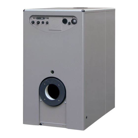
    BESCHRIJVING VAN DE KETEL 1.1 EINLEITUNG ESTELLE HE ErP sie verbrennen leich- hohen Feuerungswirkungsgrad, was eine tes Heizöl, haben eine perfekt ausge- beträchtliche Ersparnis an Brennstoff Die Gusseisen-Brennwertkessel glichene Verbrennung und einen sehr ermöglicht. 1.2 AUSSENABMESSUNGEN (Abb. 1) Estelle HE 3 ErP 4 ErP 5 ErP 6 ErP 7 ErP Tiefe (mm) 795 895 995 1095 1195 330...
  • Seite 65: Technische Merkmale

    1.3 TECHNISCHE MERKMALE ESTELLE HE 3 ErP 4 ErP 5 ErP 6 ErP 7 ErP Nutzleistung 80-60°C 25,5 33,0 40,0 48,0 59,7 50-30°C 26,7 35,5 42,2 50,5 62,8 Wärmeabgabe 26,2 34,8 41,0 49,0 61,0 Energieeffizienzklasse im Heizbetrieb Energieeffizienzklasse im Heizbetrieb 97,0 94,0 93,0 93,0 93,0 PIN -Nr. 1312CR193R 1312CR193R 1312CR193R 1312CR193R 1312CR193R Typ B23P B23P...
  • Seite 66: Wasserkreislauf

    1.7.1 sind die Brennertypen aufgeführt, Abb. 3 mit den die Kessel getestet würden. 1.7.1 Brenner mit Dauerspeisung Modell Art.-Nr. Düse Zerstäubungs- Pumpe-druk Klasse Aufgenommene Tipo ø winkel bar NOx elektrische Leistung Estelle HE 3 ErP SIME MACK 3 8099000 DELAVAN 0,55 60°S 12,5 Estelle HE 4 ErP SIME MACK 4 8099010 DELAVAN 0,75 60°W 11,0 Estelle HE 5 ErP SIME MACK 5 8099030 DELAVAN 0,85 60°W...
  • Seite 67: Kondensatablass Connection

    1.7.3 Montage des Brenners (Abb. 3/a) Die Kesseltür ist bereits für die Montage des Brenners vorbereitet (Abb. 3/a). Die Brenner müssen so geregelt werden, dass das CO mit dem Wert überein- stimmt, der in Punkt 1.3 angegeben ist, wobei eine Toleranz von ± 5% möglich ist. 1.8 KONDENSATABLASS CONNECTION (Abb. 4) sammeln die Kondensation Tropfschale ist notwendig, um die Falle zu verbinden, um einen Bürgerkrieg Entlastung Rohr (oder 25) mit einer Neigung von mindestens 5 Millimeter...
  • Seite 68: Heizraum

    INSTALLATIE 2.1 HEIZRAUM muss lt. UNI-CTI 8065 aufbereitet – um zu verhindern, dass der Wind rund werden. Die Aufbereitung des für die um den Rauchauslass Druckzonen Der Heizraum muss allen Anforderungen Heizungsanlage benutzten Wassers ist in erzeugt, in denen der Druck grö- und Normen für Heizungsanlagen ent- den folgenden Fällen zwingend notwen- ßer ist, als der Aufwärtsdruck der sprechen, die mit flüssigen Brennstoffen dig: Verbrennungsgase, muss die Öffnung...
  • Seite 69 ACHTUNG: Das braune Kabel (isoliert) wird ausschließlich zum Anschluss von Brennern mit Dauerspeisung (Typ B1) verwendet. LEGENDE Leitung Neutral Hauptschalter TS Sicherheitsaquastat TC Kesselaquastat SA Grüne Led Spannungsmessung Installationspumpe Brenner mit Direktspeisung (nicht im Lieferumfang) B1 Brenner mit Dauerspeisung (Option) B2 Brenner mit Dauerspeisung zwei Stufen (Option) TA Raumthermostat OP Zeituhr (Option) HINWEIS: - Wenn Sie einen Raumthermostat (TA) montieren, müssen Sie die Überbrückung von Klemme 4 - 5 entfernen. - Beim Anschluss der Zeituhr (OP) die Überbrückung zwischen den Klemmen 5-8 entfernen. Abb. 6...
  • Seite 70: Gebrauchsanweisung Und Wartung

    GEBRAUCHSANWEISUNG UND WARTUNG HINWEISE – Im Fall eines Defekt bzw. schlechtem Betrieb des Geräts, es ausschalten und nicht selbst versuchen, es zu reparieren oder direkt an ihm einzugreifen. Sich ausschließlich an technisches Fachpersonal wenden. – Aus Sicherheitsgründen darf der Benutzer nicht auf die Innenteile des Geräts zugreifen. Sämtliche Vorgänge, die die Entfernung der Schutzvorrichtungen oder den Zugang auf gefährliche Teile des Geräts vorsehen, müssen von qualifiziertem Personal ausgeführt werden. – Das Gerät kann von Kindern über 8 Jahren und Menschen mit eingeschränkten physischen, sensorischen oder psychischen Fähigkeiten, oder die keine entspre- chende Erfahrungen und Kenntnisse besitzen, ausschließlich unter Beaufsich- tigung benutzt werden, oder nachdem diese Anweisungen zum gefahrlosen Ge- brauch des Geräts erhalten und über die ihm innewohnenden Gefahren aufgeklärt wurden. Kinder dürfen nicht mit dem Gerät spielen. Die für den Benutzer be- stimmte Reinigungs- und Wartungseingriffe dürfen nicht von unbeaufsichtigten Kindern ausgeführt werden.
  • Seite 71: Füllen Der Anlage

    3.2.3 Füllen der Anlage ESTELLE HE Überprüfen Sie von Zeit zu Zeit, ob RONDO' 3/4 OF 3-4 ErP der Hydrometer bei kalter Anlage ESTELLE 3/4 OF Druckwerte zwischen 1 und 1,2 bar (98 und 117,6 kPa) aufweist. Wenn der Druck unter 1 bar (98 kPa) liegt, müssen Sie das beheben. 3.2.4 Ausschalten des Kessels (Abb. 7) ESTELLE HE RONDO' 5/6 OF Wenn Sie den Kessel vorübergehend 5-6 ErP ESTELLE 5/6 OF...
  • Seite 72: Frostsicherung

    und die Rauchgasableitung sauber sind nicht der Fall ist, müssen sowohl der WERDEN, was in der geltenden Ge- und ob der Kessel und die Ableitungen Kessel, als auch die Anlage vollkommen setzgebung vorgesehen worden ist. Das (Türchen, Verbrennungskammer, entleert werden. Um den Kessel und Gerät IST NICHT ZUSAMMEN MIT DEM Rauchgasleitung, Rauchkanal, die Anlage vollkommen zu entleeren, HAUSHALTSMÜLL zu entsorgen.
  • Seite 73 KAZALO OPIS PE»I 1.1 UVOD .......................... 74 1.2 MERE 1.3 TEHNI»NI PODATKI ....................... 75 1.4 IZGUBE PRI NAPELJAVAH 1.5 HIDRAVLI»NI PRIKLJU»KI ...................... 76 1.6 GORI©»A 1.7 SEZNAM PRIMERNIH GORILCEV 1.8 POVEZAVA ZA ODVAJANJE KONDENZACIJSKIH ................ 77 INSTALACIJA 2.1 KURILNICA .......................... 78 2.2 MERE KURILNICE 2.3 PRIKLJU»ITEV NA NAPELJAVO 2.4 PRIKLJU»ITEV NA DIMNO CEV 2.5 ELEKTRI»NA PRIKLJU»ITEV...
  • Seite 74: 1 Opis Pe»I

    1 OPIS PE»I 1.1 UVOD LE HE ErP delujejo na kurilno olje prihranek pri uporabi. z uravnoteæenim izgorevanjem in z Ta priroËnik vsebuje navodila za name- Litoæelezni kondenzacijski kotli ESTEL- visokim uËinkom, ki dovoljuje znaten stitev, delovanje in vzdræevanje. 1.2 MERE (Risba 1) Estelle HE 3 ErP 4 ErP 5 ErP 6 ErP 7 ErP Globina (mm) 795 895 995 1095 1195 330...
  • Seite 75: Tehni»Ni Podatki

    1.3 TEHNI»NI PODATKI ESTELLE HE 3 ErP 4 ErP 5 ErP 6 ErP 7 ErP Koristna moË 80-60°C 25,5 33,0 40,0 48,0 59,7 50-30°C 26,7 35,5 42,2 50,5 62,8 MoË komore 26,2 34,8 41,0 49,0 61,0 Razred sezonske energijske uËinkovitosti Sezonska energijska uËinkovitost 97,0 94,0 93,0 93,0 93,0 PIN številka 1312CR193R 1312CR193R 1312CR193R 1312CR193R 1312CR193R Tip B23P B23P...
  • Seite 76: Hidravli»Ni Priklju»Ki

    1.7.1 Gorilnik s stalnim dovajanjem akonika Model Puπa Kot Tlak Razred Poraba Vrsta ø upraπevanja tlaËilke NOx elektriËne energije bar Estelle HE 3 ErP SIME MACK 3 8099000 DELAVAN 0,55 60°S 12,5 Estelle HE 4 ErP SIME MACK 4 8099010 DELAVAN 0,75 60°W 11,0 Estelle HE 5 ErP...
  • Seite 77: Povezava Za Odvajanje Kondenzacijskih

    1.7.3 Montiranje gorilnika (Risba 3/a) Vrata peËi so nameπËena in pripravlje- na za montaæo gorilnika (risba 3/a). Gorilniki morajo biti regulirani tako, da je vrednost CO tista, kj je prikazana v toËki 1.3 z odstopanjem ± 5%. 1.8 POVEZAVA ZA ODVAJANJE KONDENZACIJSKIH (Risba 4) Za zbiranje kondenzacije ponve je treba povezati pasti za izpolnitev civil- nega cevi (premer 25), ki imajo naj- manj nagib 5 mm na meter. Samo plastiËne cevi izpustov nor- malne civilistov so primerne za prevoz kondenza, da odteËe kanali- Risba 3/a zacijo stanovanje.
  • Seite 78: Instalacija

    OPOMBA: napeljave in pritisk predhodnega - Mora biti primerno mehansko Aparat mora biti prikljuËen na uËin- kovit zemeljski prikljuËek. polnjenja ekspanzijske posode, morajo vzdræljiva ter slab prevodnik toplote. Podjetje SIME odklanja kakrπnokoli odgovarjati oz. ne smejo biti niæji od - Ne sme puπËati, ker bi to povzroËilo odgovornost za poπkodbe oseb, do vodnega stolpa same napeljave. njeno ohladitev. katerih bi priπlo zaradi neozemljitve Kot primer navajamo: pri 5 meter- - Mora biti postavljena Ëimbolj nav- peËi.
  • Seite 79 POZOR: Kabel rjave barve (izoli- ran) je namenjen uporabi izkljuËno za povezavo gorilnikov s stalnim dovajanjem goriva (tip B1). Linija Nevtralen IG Glavno stikalo TS Varnosni termostat TC Termostat peËi SA Zeleni led, napetost prisotna PI Pumpa za kroæenje vode Gorilnik z direktnim dovajanjem goriva (ni vkljuËeno) B1 Gorilnik s stalnim dovajanjem goriva (opcija) B2 Gorilnik s stalnim dovajanjem goriva dve stopnji (opcija) TA Prostorni termostat OP Programska ura (opcija) OPOMBA: - PrikljuËite kronotermostata (TA) in odstranite mostiËke med stiËniki 4-5. - S prikljuËitvijo programske ure (OP) odstranite mostiËek med stiËniki 5-8. Risba 6...
  • Seite 80: 3 Raba In Vzdræevanje

    3 RABA IN VZDRÆEVANJE OPOZORILA - V primeru okvare in/ali nepravilnega delovanja aparata le-tega deaktivi- rajte, prepovedano ga je popravljati ali vanj neposredno posegati. Obrni- te se izkljuËno na kvalificirano osebje. - Zaradi varnostnih razlogov uporabnik ne sme dostopati v notranjost aparata. Vsi posegi, ki zahtevajo odstranjevanje zašËit ali dostop do ne- varnih delov aparata, morajo biti izvedeni s strani kvalificiranega osebja. - Aparat lahko uporabljajo otroci, starejši od 8 let in osebe z zmanjšanimi fiziËnimi, senzoriËnimi ali duševnimi sposobnostmi, ali osebe brez izkušenj ali potrebnih znanj, Ëe so pod nadzorom ali pa so bile ustrezno pouËene o varni uporabi aparata in so razumele nevarnosti, ki so z uporabo po- vezane. Otroci se z aparatom ne smejo igrati. »išËenja in vzdrževanja, za katera je odgovoren uporabnik, ne smejo izvajati otroci brez nadzora. 3.1 PREGLED PRED VÆIGOM vkljuËitev grelca je treba odviti Ërni je pritisk niæji od 1 bar (98 kPa), poskr- pokrov in pritisniti na gumb pod njim. bite za ponovno naravnanje. Ob prvem væigu je primerno preveriti »e pogosto pride do tega pojava, naslednje: zahtevajte kontrolni ukrep pooblaπËene...
  • Seite 81: 3.3 Letno »I©»Enje

    ESTELLE HE RONDO' 3/4 OF 3-4 ErP ESTELLE 3/4 OF ESTELLE HE RONDO' 5/6 OF 5-6 ErP ESTELLE 5/6 OF Risba 8 - zapreti pipce za gorivo in vode za ogrevanje; - sprazniti sistem za ogrevanje, Ëe je nevarnost zmrzovanja. 3.3 LETNO »I©»ENJE ESTELLE Vzdræevanje generatorja je potrebno opraviti vsako leto, kar se je potrebno domeniti s pooblaπËenim tehniËnim osebjem.
  • Seite 82: Za©»Ita Proti Zmrzovanju

    - sneti komandno ploπËo (9), pri Ëe- torja za specifiËen sistem ogrevanja. mer jo stransko pritrdite s πtirimi samovreznimi vijaki; Vonj po neizgorelih ostankih goriva - sneti zadnje ploπËe (6) in (7), ki so - Preveriti ËistoËo glave generatorja in pritrjene na straneh z desetimi sa- odvoda dima, neproduπnost genera- monavojnimi vijaki; torja in odvodnih cevi (vratca, gorilna - odstraniti levo stransko ploπËo (3) komora, dimna cev, dimnik, tesnila).
  • Seite 83 Daily fuel consumption Recapiti / Datos de contacto Fonderie Sime S.p.A. Via Garbo 27, 37045 Legnago (VR) ITALIA Elementos de contacto / Contact details a. Regime ad alta temperatura: temperatura di ritorno di 60°C all’entrata e 80°C di temperatura di fruizione all’uscita dell’apparecchio b.
  • Seite 84 Täglicher Brennsto verbrauch Coordonnées / Kontaktinformationen Fonderie Sime S.p.A. Via Garbo 27, 37045 Legnago (VR) ITALIA a. Régime à haute température : température de retour de 60°C à l’entrée et 80°C de température d’utilisation à la sortie de l’appareil. b. Basse température : température de retour (à l’entrée de la chaudière) pour les chaudières à condensation 30°C, pour les chaudières à basse température 37°C et pour les autres chaudières 50°C.
  • Seite 85 Qfuel K ontakti Fonderie Sime S.p.A. Via Gar bo 27, 37045 Le gnago (VR) ITALI A a. V isokotemperaturni režim: povratna temperatura 60°C na vstopu in uporabna te mper atura 80°C na izstopu iz naprave. b. Nizkotemperaturni režim: povratna tempe ratura (na vsopu v kotel ) za kondenzacijske kotle 30° C, za nizkotemper aturne kotle 37°C in za ostale kotle 50°C.
  • Seite 86 Daily electricity consumption Recapiti / Datos de contacto Fonderie Sime S.p.A. Via Garbo 27, 37045 Legnago (VR) ITALIA Elementos de contacto / Contact details a. Regime ad alta temperatura: temperatura di ritorno di 60°C all’entrata e 80°C di temperatura di fruizione all’uscita dell’apparecchio b.
  • Seite 87 Täglicher Stromverbrauch Täglicher Brennsto verbrauch Fonderie Sime S.p.A. Via Garbo 27, 37045 Legnago (VR) ITALIA Coordonnées / Kontaktinformationen a. Régime à haute température : température de retour de 60°C à l’entrée et 80°C de température d’utilisation à la sortie de l’appareil.
  • Seite 88 Qfuel K ontakti Fonderie Sime S.p.A. Via Gar bo 27, 37045 Le gnago (VR) ITALI A a. V isokotemperaturni režim: povratna temperatura 60°C na vstopu in uporabna te mper atura 80°C na izstopu iz naprave. b. Nizkotemperaturni režim: povratna tempe ratura (na vsopu v kotel ) za kondenzacijske kotle 30° C, za nizkotemper aturne kotle 37°C in za ostale kotle 50°C.
  • Seite 89 Daily fuel consumption Recapiti / Datos de contacto Fonderie Sime S.p.A. Via Garbo 27, 37045 Legnago (VR) ITALIA Elementos de contacto / Contact details a. Regime ad alta temperatura: temperatura di ritorno di 60°C all’entrata e 80°C di temperatura di fruizione all’uscita dell’apparecchio b.
  • Seite 90 Täglicher Stromverbrauch Täglicher Brennsto verbrauch Fonderie Sime S.p.A. Via Garbo 27, 37045 Legnago (VR) ITALIA Coordonnées / Kontaktinformationen a. Régime à haute température : température de retour de 60°C à l’entrée et 80°C de température d’utilisation à la sortie de l’appareil.
  • Seite 91 Qfuel K ontakti Fonderie Sime S.p.A. Via Gar bo 27, 37045 Le gnago (VR) ITALI A a. V isokotemperaturni režim: povratna temperatura 60°C na vstopu in uporabna te mper atura 80°C na izstopu iz naprave. b. Nizkotemperaturni režim: povratna tempe ratura (na vsopu v kotel ) za kondenzacijske kotle 30° C, za nizkotemper aturne kotle 37°C in za ostale kotle 50°C.
  • Seite 92 Daily electricity consumption Recapiti / Datos de contacto Fonderie Sime S.p.A. Via Garbo 27, 37045 Legnago (VR) ITALIA Elementos de contacto / Contact details a. Regime ad alta temperatura: temperatura di ritorno di 60°C all’entrata e 80°C di temperatura di fruizione all’uscita dell’apparecchio b.
  • Seite 93 Täglicher Stromverbrauch Täglicher Brennsto verbrauch Fonderie Sime S.p.A. Via Garbo 27, 37045 Legnago (VR) ITALIA Coordonnées / Kontaktinformationen a. Régime à haute température : température de retour de 60°C à l’entrée et 80°C de température d’utilisation à la sortie de l’appareil.
  • Seite 94 Qfuel K ontakti Fonderie Sime S.p.A. Via Gar bo 27, 37045 Le gnago (VR) ITALI A a. V isokotemperaturni režim: povratna temperatura 60°C na vstopu in uporabna te mper atura 80°C na izstopu iz naprave. b. Nizkotemperaturni režim: povratna tempe ratura (na vsopu v kotel ) za kondenzacijske kotle 30° C, za nizkotemper aturne kotle 37°C in za ostale kotle 50°C.
  • Seite 95 Daily electricity consumption Recapiti / Datos de contacto Fonderie Sime S.p.A. Via Garbo 27, 37045 Legnago (VR) ITALIA Elementos de contacto / Contact details a. Regime ad alta temperatura: temperatura di ritorno di 60°C all’entrata e 80°C di temperatura di fruizione all’uscita dell’apparecchio b.
  • Seite 96 Täglicher Brennsto verbrauch Coordonnées / Kontaktinformationen Fonderie Sime S.p.A. Via Garbo 27, 37045 Legnago (VR) ITALIA a. Régime à haute température : température de retour de 60°C à l’entrée et 80°C de température d’utilisation à la sortie de l’appareil. b. Basse température : température de retour (à l’entrée de la chaudière) pour les chaudières à condensation 30°C, pour les chaudières à basse température 37°C et pour les autres chaudières 50°C.
  • Seite 97 Qfuel K ontakti Fonderie Sime S.p.A. Via Gar bo 27, 37045 Le gnago (VR) ITALI A a. V isokotemperaturni režim: povratna temperatura 60°C na vstopu in uporabna te mper atura 80°C na izstopu iz naprave. b. Nizkotemperaturni režim: povratna tempe ratura (na vsopu v kotel ) za kondenzacijske kotle 30° C, za nizkotemper aturne kotle 37°C in za ostale kotle 50°C.
  • Seite 98 NOTE...
  • Seite 100 Fonderie Sime S.p.A - Via Garbo, 27 - 37045 Legnago (Vr) Tel. +39 0442 631111 - Fax +39 0442 631292 - www.sime.it...

Inhaltsverzeichnis