Samson 5 D Einbau- Und Bedienungsanleitung

Verwandte Anleitungen für Samson 5 D


Inhaltszusammenfassung für Samson 5 D
- Seite 1 Feuerungsregler Typ 5 D Boiler controller Type 5 D Régulateur de tirage type 5 D Einbau- und Bedienungsanleitung Mounting and Operating Instructions Montage et mise en service EB 0530 D/E/F...
- Seite 2 Fig. 1: Fig. 2:...
- Seite 3 Der Regler Typ 5 D schließt die Zuluftklappe des Kessels bei stei- gender Temperatur. Der Regler kann waagerecht oder senkrecht eingebaut werden. Bei waagerechtem Einbau muss die Sechskantschraube (S) senk- recht nach oben zeigen. Für die Einregulierung gelten die roten Zahlen und die rote Marke (vgl.
- Seite 4 The Type 5 D Controller closes the air inlet flap as the temperature rises. The controller can be installed either vertically or horizontally. When installed horizontally, the hexagon screw (S) must point upwards. For control in this position, the red figures and the red mark are used (Fig. 1).
- Seite 5 Le régulateur type 5 D ferme la porte d‘aération par l‘augmentati- on de température. Le régulateur peut être monté en position horizontale ou verticale. Pour le montage horizontal, la vis 6 pans (S) occupe une position verticale. Les chiffres et les repères rouges servent au réglage (Fig. 1).
- Seite 6 Fig. 3:...
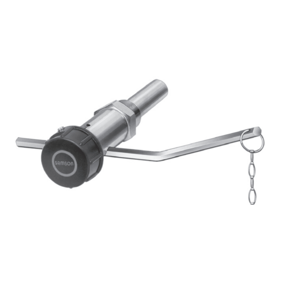
- Seite 7 Montage Tauchhülse und Regler sind fest miteinander verbunden. Zum Ein- bau Sechskantschraube (2) lockern und Hebelstange (1) so drehen, dass sie beim Einschrauben nicht stört. Lässt sich ein Herausnehmen der Hebelstange nicht vermeiden, so ist wie folgt vorzugehen: Sechskantschraube lockern, Hebelstange herausziehen und Gelenkstück (3) aus der Bohrung (5) herausneh- men.
- Seite 8 Mounting The thermowell is firmly connected to the controller. Loosen hexa- gon screw (2) and turn lever arm (1) to facilitate installation. If the lever arm must be removed to install the controller, proceed as fol- lows: loosen hexagon screw, remove lever arm and take the connecting piece (3) out of the hole (5).
- Seite 9 Montage Fourreau et régulateur sont reliés. Pour le montage, desserrer la vis 6 pans (2) et tourner le levier (1), de façon à ce qu‘il ne gêne pas le montage. Lorsque une dépose du levier ne peut être évitée, pro- céder comme suit : desserrer la vis 6 pans, retirer le levier et l‘arti- culation (3) de l‘alésage (5).
- Seite 10 Einregulierung ACHTUNG! Vor der Einregulierung zunächst überprüfen, ob die Luft- klappe frei beweglich ist und dicht abschließen kann (kein Klemmen, keine Fremdkörper). Die gewünschte Vorlauftemperatur wird am Drehknopf eingestellt und der Kessel langsam hochgeheizt, bis die eingestellte Tempera- tur erreicht ist. Jetzt wird die Hebelstange seitlich und in der Höhe so ausgerichtet, dass der kurze mit der Bohrung für die Kette verse- hene Hebelarm nach vorn gerichtet ist, ungefähr waagerecht liegt (gestrichelte Linie in den Bildern 1 und 2) und möglichst genau...
- Seite 11 Adjustment NOTICE! Before adjustment, first check whether the air inlet flap can move freely and close tightly (no wedging, no foreign bo- dies). Set required flow temperature using the knob. Allow the boiler to heat up slowly until the set temperature is reached. Arrange the le- ver arm so that short section with the bore for the chain points to the front, lies approximately horizontal (dotted line in Figs. 1 and 2) and is positioned as precisely as possible over the chain moun-...
- Seite 12 Réglage ATTENTION! Avant le réglage il faut contrôler si la porte d‘aération est mobile et peut être bien fermée (sans être serrée, et sans corps étrangers). La température du départ désirée est réglée à l‘aide du bouton de réglage ; monter progressivement la température de la chaudière jusqu‘à...
- Seite 13 Bedienung Der Vorlauftemperatur-Sollwert wird durch Verdrehen des Dreh- knopfes am Regler eingestellt. Der gewünschte Temperaturwert wird dabei mit dem der Einbaulage entsprechenden Markierungsstrich zur Deckung gebracht: Bei waagerechtem Einbau: – Rote Zahlen und roter Mar- kierungsstrich Bei senkrechtem Einbau: Weiße Zahlen und weißer –...
- Seite 14 Operation The desired flow temperature is set by turning the knob on the cont- roller. The scale to be used and the corresponding mark on the co- ver depends on the installed position of the controller: In horizontal position: Red figures and red mark –...
- Seite 15 Utilisation La consigne de la température du départ se règle sur le régulateur par rotation du bouton de réglage. Pour ce faire, mettre la valeur de la température en face du trait de repère correspondant. Pour montage horizontal: – Chiffres et repères rouges Pour montage vertical: Chiffres et repères blancs –...
- Seite 16 Fig. 4:...
- Seite 17 Auswechseln des Temperaturfühlers Vor Demontage des Reglers Drehknopf nach rechts bis zum An- schlag (30 °C) hineindrehen. Sechskantschraube (2) lockern, He- belstange (11) herausziehen, Gelenkstück (9) mit Sechskantschrau- be entfernen. Stiftschraube (3) im Drehknopf durch ca. 3 Linksdre- hungen lockern, Drehknopf mit leichtem Druck zum Reglergehäuse abschrauben.
- Seite 18 achten, dass die rechtwinklige Aussparung (10) des Gelenkstü- ckes (9) gegen den Sechskant der Tauchhülse gerichtet ist. Hebel- stange (11) einschieben und Sechskantschraube (2) fest anziehen. Darauf achten, dass die Schraube nicht auf eine Kante, sondern auf eine Fläche der Hebelstange drückt. Replacing the temperature sensor Before removing the controller, turn the knob clockwise as far as it will go (30 °C).
- Seite 19 to thermowell and mount it so that the part (6) is opposite to the ho- le (1). Fit knob on body so that the pin (5) engages in hole (4). In this case, the white mark has to point to the white figure „40“ and the red mark to the red figure „40“.
- Seite 20 Remplacement du thermostat Visser le bouton de réglage à droite jusqu‘à sa butée. Défaire la vis six pans (2), retirer le levier (11), et enlever le pivot (9) avec sa vis six pans. Défaire la vis (3) en la tournant d‘environ trois tours sur la gauche, dévisser le bouton en appuyant légèrement sur le corps du régulateur.
- Seite 21 avec la vis six pans (2) dans l‘évidement (1). Faire bien attention à diriger le bossage rectangulaire (10) du pivot (9) vers le pas de vis du régulateur. Enfiler le levier (11) et serrer la vis à six pans (2). Lors de cette opération veiller à...
- Seite 24 Ausgabe April 2013 · Edition April 2013 · Edition Avril 2013 SAMSON AG · MESS- UND REGELTECHNIK Weismüllerstraße 3 · 60314 Frankfurt am Main · Germany Phone: +49 69 4009-0 · Fax: +49 69 4009-1507 EB 0530 D/E/F www.samson.de · samson@samson.de...