Gemü 514 Montageanleitung
Umbau standardventile auf regelventile
Vorschau ausblenden
Andere Handbücher für 514:
- Original einbau- und montageanleitung (44 Seiten) ,
- Montageanleitung (40 Seiten) ,
- Originalbetriebsanleitung (40 Seiten)

Verwandte Anleitungen für Gemü 514


Inhaltszusammenfassung für Gemü 514
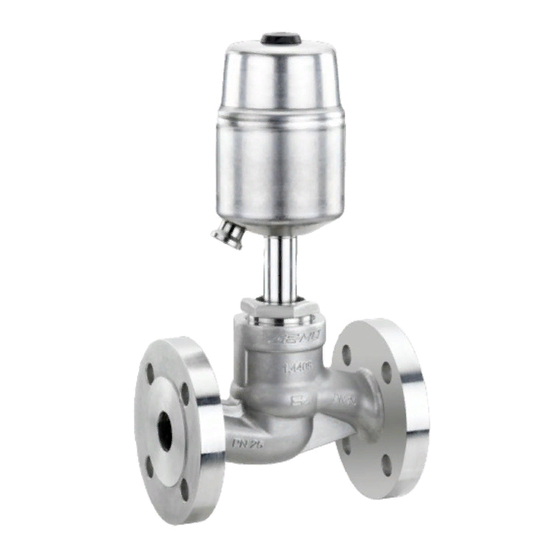
- Seite 2 All rights including copyrights or industrial property rights are expressly reserved. Dokument zum künftigen Nachschlagen aufbewahren. Keep the document for future reference. © GEMÜ Gebr. Müller Apparatebau GmbH & Co. KG 04.04.2019 2 / 16 GEMÜ 514, 530, 532, 534, 550, www.gemu-group.com...
-
Seite 3: Inhaltsverzeichnis
Steuerfunktion 1 DN 65-100 ....1.1.4 Steuerfunktion 2 / Steuerfunktion 3 DN 65-100 ..........Explosionsdarstellung ........Einbau/Auswechseln des Regelkegels ..... 2 Montage Antrieb ............DN 15-50 ............DN 65-100 ............3 / 16 www.gemu-group.com GEMÜ 514, 530, 532, 534, 550, 554... -
Seite 4: Demontage
(nur Originalteile von GEMÜ verwenden). 1. Antrieb A in Offen-Position bringen. 2. Überwurfmutter a lösen. 3. Antrieb A vom Ventilkörper 1 entfernen. 4. Antrieb A von Steuermediumleitungen trennen. 5. Dichtring 4 entnehmen. GEMÜ 514, 530, 532, 534, 550, 4 / 16 www.gemu-group.com... -
Seite 5: Steuerfunktion 1 Dn 65-100
1. Antrieb A in Offen-Position bringen. 2. Sechskantmuttern 6 lösen. 3. Antrieb A und Sitzflansch 29 vom Ventilkörper 1 entfer- nen. 4. Antrieb A von Steuermediumleitungen trennen. 5. Dichtring 30 entnehmen. www.gemu-group.com 5 / 16 GEMÜ 514, 530, 532, 534, 550,... -
Seite 6: Explosionsdarstellung
8. Tellerscheibe / Regelkegel 19 an Spindel 2 ansetzen (Spindel 2 mit geeignetem Werkzeug, das die Spindelo- berfläche nicht beschädigt, festhalten) und festziehen. 9. Neuen Dichtring 4 in Ventilkörper 1 einlegen. 10. Antrieb A montieren. GEMÜ 514, 530, 532, 534, 550, 6 / 16 www.gemu-group.com... -
Seite 7: Montage Antrieb
Bei Ventilen mit reduziertem Ventilsitz (siehe Tabelle 1) muss 7. Komplett montiertes Ventil auf Funktion und auf Dichtheit die Sitzdichtung im Ersatzteil-Set beachtet werden. prüfen. Beispiel: Ventil: 530 15D1137 51 2G1 RD303 Ersatzteil-Set: 530 15SVS 5 2xx RDxx www.gemu-group.com 7 / 16 GEMÜ 514, 530, 532, 534, 550,... - Seite 13 13 / 16 GEMÜ 514, 530, 532, 534, 550,...
- Seite 14 GEMÜ 514, 530, 532, 534, 550, 14 / 16 www.gemu-group.com...
- Seite 15 15 / 16 GEMÜ 514, 530, 532, 534, 550,...
- Seite 16 GEMÜ Gebr. Müller Apparatebau GmbH & Co. KG Änderungen vorbehalten Fritz-Müller-Straße 6-8, 74653 Ingelfingen-Criesbach, *88599638* Subject to alteration Germany 04.2019 | 88599638 Tel. +49 (0)7940 123-0 · info@gemue.de www.gemu-group.com...