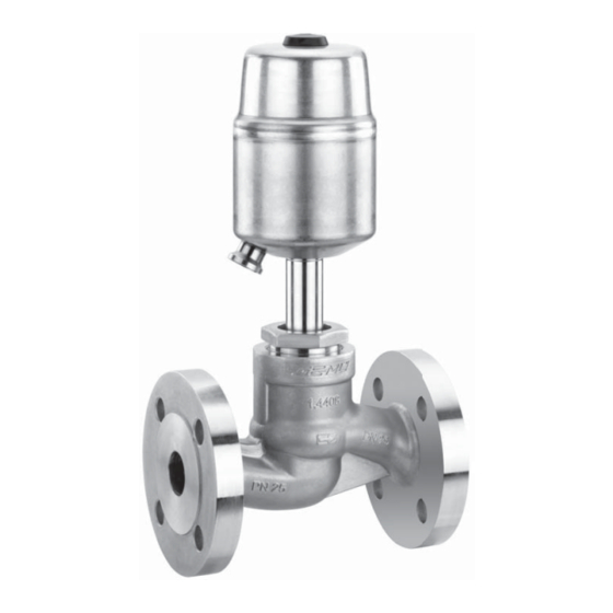
Gemü 530 Original Einbau- Und Montageanleitung
Sitzventil
Vorschau ausblenden
Andere Handbücher für 530:
- Original einbau- und montageanleitung (44 Seiten) ,
- Originalmontageanleitung (24 Seiten) ,
- Montageanleitung (16 Seiten)

Verwandte Anleitungen für Gemü 530


Inhaltszusammenfassung für Gemü 530
- Seite 1 Sitzventil Metall, DN 15 - 100 Globe Valve Metal, DN 15 - 100 ORIGINAL EINBAU- UND MONTAGEANLEITUNG INSTALLATION, OPERATING AND MAINTENANCE INSTRUCTIONS...
-
Seite 2: Inhaltsverzeichnis
Inhaltsverzeichnis Allgemeine Hinweise Voraussetzungen für die einwandfreie Allgemeine Hinweise Funktion des GEMÜ-Ventils: Allgemeine Sicherheitshinweise 2 Sachgerechter Transport und Lagerung Hinweise für Service- und Installation und Inbetriebnahme durch Bedienpersonal eingewiesenes Fachpersonal Warnhinweise Bedienung gemäß dieser Einbau- und Verwendete Symbole Montageanleitung Begriff sbestimmungen Ordnungsgemäße Instandhaltung Vorgesehener Einsatzbereich Auslieferungszustand... -
Seite 3: Hinweise Für Service- Und
Hinweise für Service- und Warnhinweise Bedienpersonal Warnhinweise sind, soweit möglich, nach folgendem Schema gegliedert: Die Einbau- und Montageanleitung enthält grundlegende Sicherheitshinweise, die bei SIGNALWORT Inbetriebnahme, Betrieb und Instandhaltung zu beachten sind. Nichtbeachtung kann zur Art und Quelle der Gefahr Folge haben: ®... -
Seite 4: Verwendete Symbole
Vorgesehener Verwendete Symbole Einsatzbereich Gefahr durch heiße Oberfl ächen! Das 2/2-Wege-Ventil GEMÜ 530 ist für den Einsatz in Rohrleitungen konzipiert. Gefahr durch ätzende Stoff e! Es steuert ein durchfl ießendes Medium indem es durch ein Steuermedium geschlossen oder geöff net werden kann. -
Seite 5: Technische Daten
Technische Daten Betriebsmedium Steuermedium Aggressive, neutrale, gasförmige, flüssige Medien und Neutrale Gase, gefiltert 50 μm Dampf, die die physikalischen und chemischen Eigen- Max. zul. Temperatur des Steuermediums: 60 °C schaften der jeweiligen Gehäuse- und Dichtwerkstoffe nicht beeinträchtigen. Steuerdruckbereich 4 - 8 bar (Details siehe unten) Medientemperatur -10 °C bis 180 °C... - Seite 6 Kv-Werte [m³/h] Nennweite DN 15 DN 20 DN 25 DN 32 DN 40 DN 50 DN 65 DN 80 DN 100 13,0 22,0 35,0 50,0 90,0 127,0 200,0 Kv-Werte ermittelt gemäß DIN EN 60534. Die Kv-Wertangaben beziehen sich auf die Steuerfunktion 1 (NC) und den größten Antrieb für die jeweilige Nennweite.
- Seite 7 Betriebsdruck- / Steuerdruckkennlinien Steuerfunktion 1: Federkraft geschlossen (NC) / Durchflussrichtung: mit dem Teller Antriebsgröße 1M1 Antriebsgröße 2M1 Antriebsgröße 3M1 min. Steuerdruck in Abhängigkeit vom min. Steuerdruck in Abhängigkeit vom min. Steuerdruck in Abhängigkeit vom Betriebsdruck Betriebsdruck Betriebsdruck DN 50 DN 20 DN 25 DN 20 DN 15...
-
Seite 8: Bestelldaten
Bestelldaten Gehäuseform Code Durchflussrichtung Code Durchgangskörper Gegen den Teller Mit dem Teller Anschlussart Code ** nur Steuerfunktion NC Flansch Flansch EN 1092 / PN16 / Form B, Baulänge EN 558, Reihe 1, ISO 5752, basic series 1 Flansch EN 1092 / PN25 / Form B, Baulänge EN 558, Reihe 1 ISO 5752, basic series 1 Flansch EN 1092 / PN40 / Form B,... -
Seite 9: Herstellerangaben
Herstellerangaben Funktionsbeschreibung Das fremdgesteuerte 2/2 Wege-Ventil Transport GEMÜ 530 ist ein Metall-Geradsitzventil mit Durchgangskörper und besitzt Ventil nur auf geeignetem Lademittel einen Kolbenantrieb. Das Ventil hat transportieren, nicht stürzen, vorsichtig bei Steuerfunktion NC serienmäßig handhaben. eine optische Stellungsanzeige (für Verpackungsmaterial entsprechend Steuerfunktion NO und DA auf Anfrage). -
Seite 10: Geräteaufbau
Geräteaufbau WARNUNG Optische Stel- Aggressive Chemikalien! lungsanzeige ® Verätzungen! (Standard bei Montage nur mit geeigneter Steuerfunktion Schutzausrüstung. VORSICHT Steuermedium- Heiße Anlagenteile! anschluss ® Verbrennungen! Nur an abgekühlter Anlage arbeiten. VORSICHT Ventil nicht als Trittstufe oder Aufstiegshilfe benutzen! ® Gefahr des Abrutschens / der Geräteaufbau Beschädigung des Ventils. -
Seite 11: Bedienung
Einbaulage: ausgeschlossen sind. Für Ventile mit Regelkegel empfehlen wir 6. Anlage bzw. Anlagenteil fachgerecht eine senkrecht stehende oder hängende dekontaminieren, spülen und belüften. Einbaulage des Antriebs zur Optimierung der Standzeit. Montage bei Flanschanschluss: Richtung des Betriebsmediums: Ventil im angelieferten Zustand einbauen: Durchfl... -
Seite 12: Steuerfunktionen
11.3 Steuerfunktionen Steuerfunktion 2, 3, 8 Folgende Steuerfunktionen sind verfügbar: Anschluss 4 Steuerfunktion 1 Federkraft geschlossen (NC): Ruhezustand des Ventils: durch Federkraft geschlossen. Ansteuern des Antriebs (Anschluss 2) öffnet das Ventil. Entlüften des Anschluss 2 Antriebs bewirkt das Schließen des Ventils durch Federkraft. -
Seite 13: Montage / Demontage Von Ersatzteilen
Montage / Demontage von 7. Geeignetes Schraubensicherungsmittel auf Gewinde von Spindel 2 auftragen. Ersatzteilen 8. Mit Mutter 16 fi xieren (Spindel 2 Siehe auch Kapitel 11.1 "Montage des mit geeignetem Werkzeug, das die Spindeloberfl äche nicht beschädigt, Ventils" und Kapitel 20 "Schnittbild und festhalten). -
Seite 14: Montage Antrieb
14. Sicherungsblech 38 auf Ventilteller 15 12.3.1 DN 15 - 50 legen. 1. Antrieb A in Off en-Position bringen. 15. Kompletten Ventilteller 15 an 2. Antrieb 360° drehbar. Position der Überwurfmutter 36 schrauben. Steuermediumanschlüsse beliebig. 16. Sicherungsblech 38 um 90° biegen, 3. -
Seite 15: Inbetriebnahme
Inbetriebnahme Inspektion und Wartung WARNUNG WARNUNG Aggressive Chemikalien! Unter Druck stehende Armaturen! ® Verätzungen! ® Gefahr von schwersten Verletzungen Vor Inbetriebnahme Dichtheit oder Tod! der Medienanschlüsse Nur an druckloser Anlage arbeiten. prüfen! VORSICHT Dichtheitsprüfung nur mit geeigneter Heiße Anlagenteile! Schutzausrüstung. ®... -
Seite 16: Demontage
Demontage Hinweise Demontage erfolgt unter den gleichen Hinweis zur Richtlinie 2014/34/EU Vorsichtsmaßnahmen wie die Montage. (ATEX Richtlinie): Ventil demontieren (siehe Kapitel 12.1 Ein Beiblatt zur Richtlinie 2014/34/ "Demontage Antrieb"). EU liegt dem Produkt bei, sofern es Leitungen des Steuermediums gemäß ATEX bestellt wurde. abschrauben (siehe Kapitel 11.3 "Steuermedium anschließen"). -
Seite 17: Fehlersuche / Störungsbehebung
Fehlersuche / Störungsbehebung Fehler Möglicher Grund Fehlerbehebung Steuermedium entweicht aus Entlüftungsbohrung* im Antriebsdeckel bei Antrieb austauschen und Steuermedium auf Antriebskolben undicht Steuerfunktion NC / Verschmutzungen untersuchen Anschluss 2* bei Steuerfunktion NO Steuermedium entweicht Antrieb austauschen und Steuermedium auf Spindelabdichtung undicht aus Leckagebohrung* Verschmutzungen untersuchen Betriebsmedium entweicht... -
Seite 18: Schnittbilder Und Ersatzteile 20.1 Dn
Schnittbilder und Ersatzteile 20.1 DN 15 - 50 Entlüftungsbohrung Anschluss 2 Leckagebohrung Pos. Benennung Bestellbezeichnung Ventilkörper K 534... Dichtring 530...SVS... Sitzdichtung Antrieb 9530 Überwurfmutter Spindel Ventilteller Mutter Tellerscheibe 18 / 44... -
Seite 19: Dn 65 - 100
20.2 DN 65 - 100 Anschluss 2 Leckagebohrung Pos. Benennung Bestellbezeichnung Ventilkörper K 534... Dichtring Sechskantmutter Sitzdichtung 530...SVS... Dichtring Zylinderschraube Antrieb 9530 Überwurfmutter Spindel Stiftschraube Ventilteller Tellerscheibe Sitzflansch Überwurfmutter Sicherungsblech 19 / 44... -
Seite 20: Einbauerklärung
29.12.2009 Projektnummer: SV-Pneum-2009-12 Handelsbezeichnung: Typ 530 Es wird erklärt, dass die folgenden grundlegenden Anforderungen der Maschinenrichtlinie 2006/42/EG erfüllt sind: 1.1.3.; 1.1.5.; 1.1.7.; 1.2.1.; 1.3.; 1.3.2.; 1.3.3.; 1.3.4.; 1.3.7.; 1.3.9.; 1.5.3.; 1.5.5.; 1.5.6.; 1.5.7.; 1.5.8.; 1.5.9.; 1.6.5.; 2.1.1.; 3.2.1.; 3.2.2.; 3.3.2.; 3.4.4.; 3.6.3.1.; 4.1.2.1.; 4.1.2.3.; 4.1.2.4.; 4.1.2.5.; 4.1.2.6. a); 4.1.2.6. b);... -
Seite 21: Eu-Konformitätserklärung
GEMÜ Gebr. Müller Apparatebau GmbH & Co. KG Fritz-Müller-Straße 6-8 D-74653 Ingelfingen erklären, dass unten aufgeführte Armaturen die Sicherheitsanforderungen der Druckgeräte- richtlinie 2014/68/EU erfüllen. Benennung der Armaturen - Typenbezeichnung Sitzventil GEMÜ 530 Benannte Stelle: TÜV Rheinland Industrie Service GmbH Nummer: 0035 Zertifi kat-Nr.: 01 202 926/Q-02 0036... - Seite 42 42 / 44...
- Seite 43 43 / 44...
- Seite 44 GEMÜ Gebr. Müller Apparatebau GmbH & Co. KG · Fritz-Müller-Str. 6-8 · D-74653 Ingelfi ngen-Criesbach Telefon +49(0)7940/123-0 · Telefax +49(0)7940/123-192 · info@gemue.de · www.gemu-group.com...