
Inhaltszusammenfassung für behnke myintercom One
- Seite 1 anleitung Version 3.0 myintercom IP-Video Türstation Seite ..3 myintercom IP video door station Page ..48 Portier téléphonique myintercom avec vidéo sur IP Page ..93...
- Seite 2 Anleitung myintercom One und myintercom Plus IP-Video Türstation Kontakt Wichtige Hinweise Bitte beachten Sie, dass Behnke Sprechstellen und Zubehörteile ausschließlich von ausgebil- deten Elektro-, Informations-, Telekommunika tionsfachkräften unter Einhaltung der einschlä- gigen Normen und Regeln installiert und gewartet werden dürfen. Achten Sie bitte darauf, dass die Geräte vor Wartungs- oder Reparaturarbeiten vom Stromnetz (Steckernetzteil) und...
-
Seite 3: Inhaltsverzeichnis
6.3. Administration der Video-Türstation ................30 6.4. Verwalten von Video-Türstationen ................34 6.5. Bedienung der App ....................... 36 7. Technische Merkmale 8. Fehlerbehebung 9. Bemaßung 9.1. myintercom One ......................41 9.2. myintercom One mit Zutrittskontrolle / myintercom Plus ..........43 10. Rechtliche Hinweise www.behnke-online.de... -
Seite 4: Einleitung
Anleitung myintercom One und myintercom Plus IP-Video Türstation Einleitung einleitung 1.1. Lieferumfang Durch die integrierte Echounterdrückung ist eine Voll-Duplex Sprachverbindung vom Smart- ▸ myintercom One IP-Video Türstation oder phone oder Tablet zur Tür gegeben. Damit kein myintercom Plus IP-Video Türstation Ruf von der Tür verloren geht, werden die letz-... - Seite 5 Anleitung myintercom One und myintercom Plus IP-Video Türstation Einleitung ▸ Bei Behnke Zweidrahttechnik ist POE IEEE Die Qualität von Bild und Sprache des Türrufs 802.3at-2009 notwendig bzw. ein passendes ist abhängig von der eingesetzten Hardware Netzteil zum Betrieb des Zweidrahtsender- / (Smartphone, Tablet).
-
Seite 6: Modellübersicht
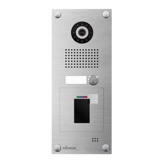
Anleitung myintercom One und myintercom Plus IP-Video Türstation Einleitung 1.3. Modellübersicht myintercom One myintercom One mit Zutrittskontrolle Kamera Modulplatz der myintercom One (Abb. Beleuchtungsring Kartenleser). Weitere Zusatzmodule: Lautsprecher Fingerprint oder Codeschloss. Ruftaste (Zusatzmodule haben immer eine autarke Beschriftungsfeld Auswerteeinheit. Dies sollte bei der Planung Mikrofon der Verdrahtung beachtet werden z.B. - Seite 7 Anleitung myintercom One und myintercom Plus IP-Video Türstation Einleitung myintercom Plus Kamera Kartenleser Beleuchtungsring Kartenleseranzeige Lautsprecher Ruftaste Beschriftungsfeld Mikrofon Schraubenabdeckung www.behnke-online.de...
-
Seite 8: Inbetriebnahme
Anleitung myintercom One und myintercom Plus IP-Video Türstation Inbetriebnahme inbetriebnahme 2.1. Empfohlene Montage-Position 2.2. Lichtverhältnisse Für einen optimalen Blickwinkel der Kamera, Um eine bessere Bildqualität bei schlechten wird eine Installationshöhe von 155 cm emp- Lichtverhältnissen oder nachts zu erhalten, fohlen. Weitere Einzelheiten entnehmen Sie wird eine Außenbeleuchtung empfohlen. -
Seite 9: Datenschutz / Datensicherheit
Anleitung myintercom One und myintercom Plus IP-Video Türstation Inbetriebnahme 2.4. Datenschutz / Datensicherheit 2.5. Beschriftungsfelder wechseln Ihr Datenschutz und Datensicherheit sind uns sehr wichtig. Bitte beachten Sie daher folgende Hinweise. ▸ Für maximale Sicherheit verwendet die Tür- sprechanlage dieselben Verschlüsselungs- technologien wie beim Onlinebanking. -
Seite 10: Türstation Anbringen
Anleitung myintercom One und myintercom Plus IP-Video Türstation Inbetriebnahme 2.6. Türstation anbringen Das Beispiel zeigt die Montage der Aufputz- variante. Die Türstation kann alternativ auch Unterputz montiert werden. Hierfür wird das passende Unterputzgehäuse in die Wandöffnung flächenbünding mit dem Edelputz eingeputzt. -
Seite 11: Einsatzszenarien
Anleitung myintercom One und myintercom Plus IP-Video Türstation Inbetriebnahme 2.7. Einsatzszenarien Lokal Die Grafik zeigt die Verwendung innerhalb eines Wohn- oder Bürogebäudes mit Zugriff über das lokale WLAN. Büro-Etage Tablet / Smartphone WLAN myintercom Plus Video- Foyer Türstation mit Kamera... - Seite 12 Anleitung myintercom One und myintercom Plus IP-Video Türstation Inbetriebnahme Global Die Grafik zeigt die Verwendung außerhalb eines Wohn- oder Bürogebäudes mit Zugriff via Internet. INTERNET Büro-Etage WLAN / 3G / LTE Sprache, Bild myintercom Plus Video- Foyer Türstation mit Kamera...
- Seite 13 Anleitung myintercom One und myintercom Plus IP-Video Türstation Inbetriebnahme Lokal oder Global (mit Sicherheitsrelais) Die Grafik zeigt die Verwendung innerhalb eines Wohn- oder Bürogebäudes mit innen- liegendem Sicherheitsrelais. Büro-Etage Tablet / Smartphone WLAN myintercom Plus Video- Foyer Türstation mit Kamera...
-
Seite 14: Installation
Anleitung myintercom One und myintercom Plus IP-Video Türstation Installation installation Elektronik myintercom One (12 V DC / AC max. 9 W). Siehe Kapitel „3.3. Türöffner/Relais/Gong“ auf Seite 18. Relais 1 (Türöffnerrelais) Potentialfreier Anschluss (belastbar mit max. 60VDC / 50VAC, max. 60W / 62,5VA, max. - Seite 15 Anleitung myintercom One und myintercom Plus IP-Video Türstation Installation Elektronik myintercom Plus Ethernetbuchse Der LAN-Anschluss erfolgt üblicherweise über einen RJ-45 Stecker . Alternativ lassen sich die einzelnen Adern aber auch via Klemmleiste anbinden : Das Netzwerk wird auf die mit 1 (orange-weiß), 2 (orange) 3 (grün-weiß) und 6...
- Seite 16 Anleitung myintercom One und myintercom Plus IP-Video Türstation Installation Elektronik myintercom Plus mit Zweidrahttechnik Gonganschlüsse Potentialfreie Anschlüsse für drei Tür- gongs (belastbar mit 60VDC / 50VAC, max. 60W / 62,5VA, max. 2A) die bei Tastendruck aktiviert werden. Siehe Kapitel „3.3. Türöff- ner/Relais/Gong“...
-
Seite 17: Poe
Anleitung myintercom One und myintercom Plus IP-Video Türstation Installation Die myintercom Plus IP-Video Türstation 2-Draht Übertrager. Nehmen Sie den Gehäuse- bietet mehrere Optionen die Türstation und deckel der Türstation ab und schließen Sie die Zusatzmodule mit Energie zu versorgen. ein Koaxialkabel an die dafür vorgesehene Buchse am Zweidrahtsender an. -
Seite 18: Türöffner/ Relais / Gong
Anleitung myintercom One und myintercom Plus IP-Video Türstation Installation 3.3. Türöffner/ Relais / Gong Wird der Türöffner direkt über die Türstation versorgt, so kann ein externer Türöffnertaster Nehmen Sie den Gehäusedeckel der Türsta- angeschlossen werden, um die Tür zu öffnen. -
Seite 19: Türgong Einstellen
Anleitung myintercom One und myintercom Plus IP-Video Türstation Installation 3.4. Türgong einstellen Die Türgongs werden an die Anschlussklem- men mit der Bezeichnung „Gong“ angeschlos- sen. Taste 1 schaltet Gong 1, Taste 2 schaltet Die Anzahl der pro Tastendruck an der Türsta- Gong 2,…... -
Seite 20: Zusatzmodule
Anleitung myintercom One und myintercom Plus IP-Video Türstation Zusatzmodule ZusatZmodule 4.1. Sicherheitsrelais Das Sicherheitsrelais wird mit vier Adern an die Türstation angeschlossen und durch diese auch mit Energie versorgt. Wird der Türöffner durch die Türstation mit Energie versorgt, so beachten Sie auch hier die maximale Leitungslänge von 50m und den minimalen... - Seite 21 Anleitung myintercom One und myintercom Plus IP-Video Türstation Zusatzmodule Anschluss myintercom One Anschluss myintercom Plus Mit Hilfe des Resettasters wird ein Reset Ebenfalls besteht die Möglichkeit bei der der Türstation durchgeführt, wenn der myintercom Plus Türstation ein zweites Sabotagekontakt ausgelöst hat. Stellen Sie Zusatzrelais zu nutzen.
- Seite 22 Anleitung myintercom One und myintercom Plus IP-Video Türstation Zusatzmodule TÖ Optionale ext. Bestätigungs- taste (bauseits) Optionale ext. Tür- Beleuchtungsteuerung, öffnertaste (bauseits) TÖ Garagentoröffner, zweiter Türöffner, Schrankensteuerung, ... Externes Türöffner Netzteil Externes Netzteil (siehe techn. Merkmale) (siehe techn. Merkmale) Relais 1 und Türöffner Relais 2 (nur bei myintercom Plus nutzbar) Wichtig! Bitte beachten Sie, dass die myintercom Plus IP-Video Türstation lediglich einen...
-
Seite 23: Kartenleser Der Myintercom Plus
Anleitung myintercom One und myintercom Plus IP-Video Türstation Kartenleser der myintercom Plus kartenleser der myintercom Plus Es besteht die Möglichkeit die myintercom Wenn die Anzeige blinkt, können Änderungen Plus IP-Video Türstation mit einem integrierten vorgenommen werden. Kartenleser zu erwerben. So kann eine einfache... -
Seite 24: Speicherplatz Auswählen
Anleitung myintercom One und myintercom Plus IP-Video Türstation Kartenleser der myintercom Plus 5.1. Speicherplatz auswählen 5.2. Transponder Transponder programmieren Halten Sie die Masterkarte vor den Kartenleser. Die Anzeige schaltet sich ein: Achtung: Bei der Programmierung ist darauf zu achten, dass kein bereits belegter Speicherplatz mit einer neuen Nummer überschrieben wird, da... -
Seite 25: Türöffnerzeit Konfigurieren
Anleitung myintercom One und myintercom Plus IP-Video Türstation Kartenleser der myintercom Plus 5.3. Türöffnerzeit konfigurieren Transponder löschen Halten Sie die Masterkarte vor den Kartenleser Die Türöffnerzeit kann vom Benutzer von 0,5 und wählen Sie den gewünschten Speicherplatz Sekunden bis 9 Sekunden eingestellt werden. -
Seite 26: Zweite Masterkarte
Anleitung myintercom One und myintercom Plus IP-Video Türstation Kartenleser der myintercom Plus 5.4. Zweite Masterkarte Halten Sie die Masterkarte erneut vor den Kartenleser, während die Anzeige blinkt. Die Zweite Masterkarte programmieren angezeigte Zeit wird programmiert und der rechte Dezimalpunkt leuchtet. - Seite 27 Anleitung myintercom One und myintercom Plus IP-Video Türstation Kartenleser der myintercom Plus Halten Sie die Werksmasterkarte vor den Kartenleser. Die zweite Masterkarte wird gelöscht und der rechte Dezimalpunkt erlischt. Die zweite Masterkarte kann nun entfernt werden. Die Anzeige erlischt. Hinweis: Ein bereits als Ausweis gespeicher- ter Transponder kann nicht als 2.Masterkarte...
-
Seite 28: Konfiguration
Anleitung myintercom One und myintercom Plus IP-Video Türstation Konfiguration konfiguration Die myintercom App wird ständig um neue Features und Funktionen erweitert, das neuste Handbuch kann über die Webseite www.myintercom.de angefordert werden. 6.1. Starten der App „myintercom“ 6.2. Übersicht Laden Sie die App „myintercom“ je nach Typ... - Seite 29 Anleitung myintercom One und myintercom Plus IP-Video Türstation Konfiguration Historie Administration Auf dieser Seite können Sie die letzten Anrufe Auf dieser Seite nehmen Sie die Einrichtung von der Tür mit Uhrzeit und Bild einsehen. Die der Video-Türstation und der App vor.
-
Seite 30: Administration Der Video-Türstation
Anleitung myintercom One und myintercom Plus IP-Video Türstation Konfiguration 6.3. Administration der Video-Türstation “ aus, um Wählen Sie hier „Administration die Video-Türstation zu verwalten. Vorher Alle für das myintercom-System notwendigen werden Benutzername und Passwort Einstellungen können mit Hilfe der App auf... - Seite 31 Anleitung myintercom One und myintercom Plus IP-Video Türstation Konfiguration Administration Im Administrationsbereich können Sie ▸ Benutzer hinzufügen ▸ Benutzer verwalten ▸ Die Besucherhistorie ein- oder ausschalten ▸ Den NTP-Server einrichten (Somit wird im Anrufprotokoll immer die korrekte Uhrzeit angezeigt.) ▸...
- Seite 32 Anleitung myintercom One und myintercom Plus IP-Video Türstation Konfiguration Benutzer verwalten Der Benutzername und das Passwort werden automatisch ausgefüllt. Geben Sie einen “ ein, um den Benutzer später leichter Drücken Sie „Hinzufügen“, um einen neuen „Namen “ Benutzer anzulegen oder auf einen Benut- identifizieren zu können.
- Seite 33 Anleitung myintercom One und myintercom Plus IP-Video Türstation Konfiguration Weisen Sie hier dem Benutzer eine Türklingel zu (nur bei myintercom Plus): www.behnke-online.de...
-
Seite 34: Verwalten Von Video-Türstationen
Anleitung myintercom One und myintercom Plus IP-Video Türstation Konfiguration 6.4. Verwalten von Video-Türstationen Türstation hinzufügen Drücken Sie auf dem Startbildschirm auf „Ein- stellungen“, der Einstellungs-Bildschirm wird angezeigt. Tragen Sie die Daten des unter „Administration “ (s. Seite 30) angelegten Benutzers hier “... - Seite 35 Anleitung myintercom One und myintercom Plus IP-Video Türstation Konfiguration “ , um weitere Der Bezug zur IP-Video Türstation wird auch hier Drücken Sie auf „Impressum wieder über den Benutzernamen hergestellt. Informationen zum Hersteller der App zu Somit ist keine weitere Angabe der hinzuzufü- erhalten.
-
Seite 36: Bedienung Der App
Anleitung myintercom One und myintercom Plus IP-Video Türstation Konfiguration 6.5. Bedienung der App In der unteren Liste sehen Sie die auf diesem Smartphone konfigurierten IP-Video Die App gliedert sich in zwei Teile: Live-Video Türstationen. Der Punkt vor dem Namen zeigt und Historie. - Seite 37 Anleitung myintercom One und myintercom Plus IP-Video Türstation Konfiguration Historie Mit Hilfe der Historien-Funktion können Sie später nachvollziehen, wer während Ihrer Abwesenheit geklingelt hat. In der oberen Leiste wird der Zeitpunkt des Türrufes angezeigt . Durch Wischen oder Drücken der Pfeil-Knöpfe in der oberen Leiste können Sie die bis zu 20 Einträge abrufen.
-
Seite 38: Technische Merkmale
Anleitung myintercom One und myintercom Plus IP-Video Türstation Technische Merkmale technische merkmale Standardmerkmale der IP-Video Türstation: Optik ▸ ▸ IP-Kamera Horizontaler Bildwinkel 180° ▸ ▸ Infrarot-Beleuchtungsring Vertikaler Bildwinkel 90° ▸ Lautsprecher ▸ Mikrofon Video ▸ ▸ Echounterdrückung Motion-JPEG, H.264 Kompression ▸... - Seite 39 Anleitung myintercom One und myintercom Plus IP-Video Türstation Technische Merkmale Zusatzmodule für myintercom Plus Wichtig! Bitte beachten Sie, dass es sich bei ▸ Ausführungsvariante der myintercom Plus der angegebenen Leistungsaufnahme ledig- Video-Türstation mit Kartenleser (nur eine lich um die Aufnahme der Türstation inklusive Ruftaste möglich)
-
Seite 40: Fehlerbehebung
Anleitung myintercom One und myintercom Plus IP-Video Türstation Fehlerbehebung fehlerbehebung Die Relais schalten nicht jeweiligen Anschlussmöglichkeit passt (Ver- wendung von PoE, Zweidrahttechnik). Sehen ▸ Lokal Sie dazu in Kapitel „3. Installation“ nach. Bitte überprüfen Sie, ob der Gehäusedeckel Nehmen Sie den Gehäusedeckel ab und kont- angeschraubt ist, da sonst der Sabotagekon- rollieren Sie bitte, ob die grüne Power-LED auf... -
Seite 41: Bemaßung
Anleitung myintercom One und myintercom Plus IP-Video Türstation Bemaßung bemassung BEMASSUNGEN 9.1. myintercom One myintercom One myi0001A - myi0004A Frontblende Seitenansicht 12,5 • Wir empfehlen eine Hohlraumtiefe von 60-70 mm (inklusive Platz für die Verkabelung) • Bohrungen mit Gewinde M4 =... -
Seite 42: Unterputzgehäuse
BEMASSUNGEN Anleitung myintercom One und myintercom Plus IP-Video Türstation myintercom One Bemaßung myi0001A - myi0004A Unterputzgehäuse myintercom One Abdeckblende myintercom One 12,5 myi0101 myi0120 - myi0123 • Wir empfehlen eine Hohlraumtiefe Unterputzgehäuse von 60-70 mm (inklusive Platz für die Verkabelung) •... -
Seite 43: Myintercom One Mit Zutrittskontrolle / Myintercom Plus
Anleitung myintercom One und myintercom Plus IP-Video Türstation Bemaßung 9.2. myintercom One mit Zutrittskontrolle myintercom One mit Zutrittskontrolle myintercom One mit Zutrittskontrolle / myintercom Plus myi0040 - myi0051 myi0040 - myi0051 myintercom Plus myintercom Plus myi0007A - myi0038A myi0007A - myi0038A... - Seite 44 Ø 3 Anleitung myintercom One und myintercom Plus IP-Video Türstation Bemaßung Unterputzgehäuse myintercom One mit Abdeckblende myintercom One mi Zutrittskontrolle und myintercom Plus Zutrittskontrolle und myintercom P myi0103 myi0124 - myi0127 Unterputzgehäuse Frontansicht Seite Ø 5,5 Ø 5 Boden / Deckel Ø...
-
Seite 45: Rechtliche Hinweise
Anleitung myintercom One und myintercom Plus IP-Video Türstation Rechtliche Hinweise rechtliche hinweise Infos zum Produkthaftungsgesetz: 1. Änderungen an unseren Produkten, die dem 1. Alle Produkte aus dieser Anleitung dürfen technischen Fortschritt dienen, behalten wir nur für den angegebenen Zweck verwendet uns vor. - Seite 46 instructions Version 3.0 myintercom IP-Video Türstation Seite ..3 myintercom IP video door station Page ..48 Portier téléphonique myintercom avec vidéo sur IP Page ..93...
- Seite 47 Contact Important Information Please note that Behnke intercoms and accessories may only be installed and serviced by qualified electricians, IT and telecommunications technicians who comply with the corresponding norms and regulations. Before carrying out service and maintenance work, please ensure that the devices are safely disconnected from the power grid (unplug power supply unit) and are disconnected from any other network and that all relevant safety regulations will be maintained.
- Seite 48 6.4. Administration of video door intercom stations ........................80 6.5. Using the app........................82 7. Technical Specifications 8. Error correction 9. Dimensions 9.1. myintercom One .......................87 9.2. myintercom One with access control / my intercom Plus ............89 10. Legal Information www.behnke-online.de...
-
Seite 49: Introduction
Integrated echo cancellation enables a full- duplex connection from your smartphone or ▸ myintercom One IP video door intercom or tablet to your front door. Your door intercom myintercom Plus IP video door intercom saves the last 20 events with camera image and ▸... - Seite 50 WiFi coverage) that there is a large number of devices featuring ▸ The app “TC Behnke” from the Apple® the Android operating system and an even AppStore® or Google Play® respectively (the larger number of different versions of the said app must remain an active process in the operating system.
-
Seite 51: Available Models
Instructions myintercom Plus IP video door intercom Introduction 1.3. Available models myintercom One myintercom One with access control Camera Module slot on the myintercom One Illumination (illustration card reader). Other additional Speaker modules: Fingerprint reader or code lock. Call button... - Seite 52 Instructions myintercom Plus IP video door intercom Introduction myintercom Plus Camera Card reader Illumination Card reader display Speaker Call button Labels Microphone Screw covers www.behnke-online.de...
-
Seite 53: Commissioning
(cf. chapter "7. Technical Specifications" on page 83) Please note the following advice on camera position when installing your Behnke door intercom system: In order to receive an image feed, you need a lot more than to simply point the camera in the direction of an object or a person. -
Seite 54: Privacy / Data Protection
▸ Please observe all country-specific legal provi- Then return the cover back onto the station – done. sions for the operation of video door intercom systems as they apply to your location of installation. www.behnke-online.de... -
Seite 55: Mounting The Door Intercom
It needs to be in full contact with the level underground. Insert the door intercom into the housing and use the four screws to fix it to the on-wall housing. Then mount the screw covers – done! www.behnke-online.de... -
Seite 56: Possible Applications
Plus video Foyer door intercom with camera WiFi DSL-Router / Switch Additional relay (garage) Ethernet Open door function Requires an internet connection for the myintercom station Please verify technical data for the door open function and the myintercom station www.behnke-online.de... - Seite 57 Plus video Foyer door intercom with camera DSL-Router / Switch additional relay Ethernet (barrier) Open door function Requires an internet connection for the myintercom station Please verify technical data for the door open function and the myintercom station www.behnke-online.de...
- Seite 58 When using two-core technology, please take com One door intercom) note of the technical specifications (use of the existing line). Requires an internet connection for the myintercom station Please verify technical data for the door open function and the myintercom station www.behnke-online.de...
-
Seite 59: Installation
(12 V DC/AC max. 9 W). Cf. Chapter "3.3. Open door/Relay/Gong" on page 63. Electronics myintercom One Relay 1 (open door function relay) Potential-free connection (max. load is max. 60VDC / 50 VAC, max. 60 W, 62.5 VA, max. - Seite 60 Open door/Relay/Gong" on page 63. Relay 2 (additional relay) Potential-free connection (max. load is max. 60VDC / 50 VAC, max. 60 W, 62.5 VA, max. 2A) to be activated via the “myintercom” app. Cf. Chapter "3.3. Open door/Relay/Gong" on page www.behnke-online.de...
- Seite 61 Please note: It is not possible to simultaneously use a two-core transmitter and Ethernet. When using the two-core technology, use a separate twisted cable for connection between 2-core transmitter and receiver. This cable may not be used to transmit any other signals or voltages. www.behnke-online.de...
-
Seite 62: Poe
2-core transmitter and receiver. This 3.2. Two-core installation cable may not be used to transmit any other signals or voltages. A second option to supply power to your door intercom station is using the additional two- www.behnke-online.de... -
Seite 63: Open Door/Relay/Gong
Please note: The open door voltage and relay 1 will always be switched in parallel. External power supply unit (cf. technical features) Illumination control Garage door open function, Barrier control Optional external open door function button (supplied on site) Connection relay 2 www.behnke-online.de... -
Seite 64: Set A Door Gong
Important! To enable tamper protection, the cover needs to be reattached to the housing after connection! Important! To enable tamper protection, the cover needs to be reattached to the housing after connection! www.behnke-online.de... -
Seite 65: Additional Modules
50VDC/ 60VAC, 60W/ 62,5VA, max. 2A. This module provides additional safety by Potential-free contact, needs a separate power moving the door open function and the two supply unit for the connected device. relays inside the protected area of your home. www.behnke-online.de... - Seite 66 Instructions myintercom Plus IP video door intercom Additional modules Connection myintercom One Connection myintercom Plus The reset key performs a reset on the door Additionally, the myintercom Plus door intercom intercom station, after the tamper contact has enables you to use a second additional relay.
- Seite 67 This open door function may only be connected to the safety relay or to the door intercom station. Please note: The safety relay does not provide separately controlled relays, it replaces relay 1 and relay 2 as well as the tension for the door opening device of the door intercom. www.behnke-online.de...
-
Seite 68: Card Reader For Myintercom Plus
153) For memory positions from 0 to 99, the decimal point will not light up (e.g. “ ” for 53). This decimal point indicates, whether the current memory position is in use or not (e.g. “ ”: memory position 138 is used for 3.8. a transponder). www.behnke-online.de... -
Seite 69: Select A Memory Position
Now, you can delete this transponder. The display will then switch to the following memory position. To terminate transponder saving, remove the master card, the display will turn off and the card reader returns to operating mode. www.behnke-online.de... -
Seite 70: Configuring Open Door Time
= 9 seconds Remove the master card, when the desired time appears on the display. The display will light up for approx. 3 consecutive seconds and then start flashing for approx. 6 seconds. www.behnke-online.de... -
Seite 71: Additional Master Card
To ensure maximum security, the default master card can only be programmed by Telecom Behnke GmbH. Therefore, you should always keep it in a safe place. It is possible to assign an additional transponder as a 2nd master card next to the default master card. - Seite 72 190 (“ ”). Then, the following will be displayed: Remove the default master card from the card reader. The display will light up for approx. 3 consecutive seconds and then start flashing for approx. 6 seconds. www.behnke-online.de...
-
Seite 73: Configuration
Please note: You cannot add a door intercom using the administrator's access information, this step requires user information. This terminates the commissioning of your myintercom. You see this screen when you start the app. www.behnke-online.de... - Seite 74 Use this screen to change settings on both the intercom including calling time and image app and your video door intercom. recorded at the time of the call. Speech / voice data is not recorded. Each video door intercom keeps a log of the last 20 visitors. www.behnke-online.de...
-
Seite 75: Administration Of The Video Door Intercom Device
“ to log on to the video door intercom. Alternatively, you can click on the QR code symbol to scan the code from the camera supplement. When the switch “Save login” is ticked, the admin data will be saved to the app upon first login. www.behnke-online.de... - Seite 76 Set-up the NTP server (in order for the call log to always show the correct calling time) ▸ Turn the infrared illumination to automatic or turn it off ▸ Change settings for “Brightness and Contrast” of the image feed www.behnke-online.de...
- Seite 77 The myintercom One does not provide this option, as it only comes with a single bell button. The user receives a push notification, as soon as the corresponding bell button is pressed.
- Seite 78 Instructions myintercom Plus IP video door intercom Configuration Please assign a door bell to the user (only for myintercom Plus): www.behnke-online.de...
-
Seite 79: Administration Of Video Door Intercom Stations
Press “Info “ receive addi- tional information and help for the installed app. Press the “Handsfree “ key to activate or deactive the handsfree mode. www.behnke-online.de... - Seite 80 Use the “Check “ key to verify, if the internet function of the door intercom has been enabled. In case the option “Confirm action” has been activated, every action, e.g. activativing the door open function, will prompt a security query. www.behnke-online.de...
-
Seite 81: Using The App
On this screen you will see the video feed from the door camera. The bar at the top of the screen indicates video reception either via local or mobile data connection. The bar colour indicates the transmission quality (red: poor, green: good). www.behnke-online.de... - Seite 82 20 entries. Choose which door intercom camera his- tory you want to access from the lower table Once again, the dot in front of the video door intercom station indicates its availability. www.behnke-online.de...
-
Seite 83: Technical Specifications
Universal open door function 6-12V DC /AC, Resolution, frame rate and quality are dynam- max. 9W, may be supplied directly ically adjusted to the network connection Audio myintercom One and myintercom One witch ▸ access control Proprietary audio transmission to the ▸... - Seite 84 Optional safety relay consumption for the door intercom station plus ▸ A myintercom One door intercom may also be the open door function in use, should the latter equipped with one of the following additional be directly supplied from the door intercom modules: station.
-
Seite 85: Error Correction
When also using the additional module “safety relay” Please verify the wiring from the door intercom Status LED myintercom One station to the safety relay (cf. chapter „4.1. Sich- erheitsrelais“). Please restart the entire myinter- com Plus device and then press the switch on the safety relay for at least 2 seconds. -
Seite 86: Dimensions
Instructions myintercom Plus IP video door intercom Dimensions dimensions BEMASSUNGEN 9.1. myintercom One myintercom One myi0001A - myi0004A Front cover Side view 12,5 ▸ We recommend a cavity depth of • Wir empfehlen eine Hohlraumtiefe von 60-70 mm (inklusive Platz für 60-70mm (incl. -
Seite 87: In-Wall Housing
BEMASSUNGEN Instructions myintercom Plus IP video door intercom myintercom One Error correction myi0001A - myi0004A Unterputzgehäuse myintercom One Abdeckblende myintercom One 12,5 myi0101 myi0120 - myi0123 • Wir empfehlen eine Hohlraumtiefe In-wall housing von 60-70 mm (inklusive Platz für die Verkabelung) •... -
Seite 88: Myintercom One With Access Control / My Intercom Plus
Instructions myintercom Plus IP video door intercom Dimensions 9.2. myintercom One with access control / my intercom Plus myintercom One mit Zutrittskontrolle myintercom One mit Zutrittskontrolle myi0040 - myi0051 myi0040 - myi0051 myintercom Plus myintercom Plus myi0007A - myi0038A myi0007A - myi0038A... - Seite 89 Ø 3 Instructions myintercom Plus IP video door intercom Dimensions Unterputzgehäuse myintercom One mit Abdeckblende myintercom One mi Zutrittskontrolle und myintercom Plus Zutrittskontrolle und myintercom P myi0103 myi0124 - myi0127 In-wall housing Front view Side Frontansicht Seite Ø 5,5 Ø 5...
-
Seite 90: Legal Information
Germany and the EU. Electromagnetic Compatibility Low Voltage Directive All our products meet the standards for CE cer- tification valid in the entire EU: EMC according to 2004/108/EC as well as low voltage directive according to 2006/95/EC www.behnke-online.de... - Seite 91 manuel Version 3.0 myintercom IP-Video Türstation Seite ..3 myintercom IP video door station Page ..48 Portier téléphonique myintercom avec vidéo sur IP Page ..93...
- Seite 92 Contact Remarques importantes Veuillez vous assurer que les dispositifs et accessoires Behnke ne sont installés et entretenus que par des électriciens, informaticiens et techniciens réseau agréés et respectant les normes et régu- lations en vigueur. Avant d'effectuer des travaux d'entretien ou de réparation, toujours débrancher les appareils des réseaux électrique (bloc d'alimentation), informatique et téléphonique et respec-...
- Seite 93 6.4. Gestion des portiers téléphoniques vidéo ............... 120 6.5. Utilisation de l'appli ....................... 122 7. Caractéristiques techniques 8. Résolution des problèmes 9. Cotation 9.1. myintercom One ......................127 9.2. myintercom One avec contrôle d'accès / myintercom Plus ..........129 10. Informations légales www.behnke-online.de...
-
Seite 94: Introduction
Afin de ne manquer aucun appel au niveau de la porte, ▸ Portier téléphonique myintercom One IP vidéo les derniers 20 évènements avec photo et heure ou portier téléphonique myintercom Plus IP sont sauvegardés dans le portier téléphonique. - Seite 95 Wifi (l’entreprise installant le système doit Veuillez prendre en compte qu’il existe un s’assurer de la bonne couverture wifi) grand nombre d’appareils équipés de systèmes ▸ L’appli « TC Behnke » téléchargeable depuis d'exploitation Android et qu’il existe un grand l’AppStore Apple ou Google Play Store nombre de versions de ce système.
-
Seite 96: Aperçu Du Modèle
Manuel myintercom Plus Introduction 1.3. Aperçu du modèle myintercom One myintercom One avec contrôle d’accès Caméra Anneau d'éclairage Emplacement de module myintercom One Haut-parleur (ill. lecteur de carte) Autres modules complé- Bouton d'appel mentaires : empreinte digitale ou digicode. Champ d'inscription (Les modules complémentaires disposent tou-... - Seite 97 Manuel myintercom Plus Introduction myintercom Plus Caméra Lecteur de cartes Anneau d'éclairage Écran du lecteur de cartes Haut-parleur Bouton d'appel Champ d'inscription Microphone Cache-vis www.behnke-online.de...
-
Seite 98: Mise En Service
à la page 128) Veuillez respecter les consignes suivantes relatives à la position de la caméra pour l’ins- tallation du portier Behnke : afin d’obtenir une image, il ne suffit pas de pointer une caméra sur un objet ou une personne. L’éclairage, l’angle d’ouverture de la caméra (horizontal/vertical),... -
Seite 99: Protection Et Sécurité Des Données
à l’endroit demandés. Placer et visser de nouveau le couvercle du boîtier. Et ▸ Respecter toutes les dispositions légales voilà ! spécifiques au pays en vigueur et relatives aux portiers téléphoniques. www.behnke-online.de... -
Seite 100: Placer Le Portier Téléphonique
Le joint d’étanchéité doit être placé en contact avec toute la surface du support plane. Placer le portier téléphonique dans le boîtier puis le fixer au boîtier en saillie à l’aide de quatre vis. Visser ensuite le cache-vis. Et voilà ! www.behnke-online.de... -
Seite 101: Exemples D'utilisation
Étage de bureaux Tablette / smartphone Wifi Portier téléphonique vidéo Foyer myintercom Plus avec caméra WIFI Routeur ADSL / switch Relais sup- plémentaire (garage) Ethernet Gâche Connexion internet myintercom absolument nécessaire Respecter les caractéristiques techniques de la gâche et de myintercom www.behnke-online.de... - Seite 102 WIFI / 3G / LTE voix, image Portier téléphonique vidéo Foyer myintercom Plus avec caméra Routeur ADSL / switch Relais sup- plémentaire Ethernet (barrière) Gâche Connexion internet myintercom absolument nécessaire Respecter les caractéristiques techniques de la gâche et de myintercom www.behnke-online.de...
- Seite 103 ▸ myintercom Plus (également possible avec Lors de l’utilisation d’une technologie à deux myintercom One) fils, respecter les spécifications techniques (utilisation du câble fourni). Connexion internet myintercom absolument nécessaire Respecter les caractéristiques techniques de la gâche et de myintercom...
-
Seite 104: Installation
Manuel myintercom Plus Installation installation Électronique myintercom One Gâche/Relais/Sonnette“ à la page 108. Relais 1 (relais gâche) Connexion à potentiel isolé (résistant à max. 60VDC / 50VAC, max. 60W / 62,5VA, max. 2A) pour une gâche s’activant via l’appli « myinter- com ». - Seite 105 à la page 108. Relais 2 (relais supplémentaire) Connexion à potentiel isolé (résistant à max. 60VDC / 50VAC, max. 60W / 62,5VA, max. 2A) pouvant être activé via l’appli « myintercom ». Voir chapitre „3.3. Gâche/Relais/Sonnette“ à la page 108. www.behnke-online.de...
- Seite 106 Lors de l’utilisation de la technologie à deux fils, utiliser un câble torsadé propre pour le raccorde- ment entre l’émetteur et le récepteur 2 fils. Il ne doit pas y avoir d’autres signaux ou tensions dans le même câble. www.behnke-online.de...
-
Seite 107: Poe
3.2. Technique à deux fils le raccordement entre l’émetteur et le récepteur 2 fils. Il ne doit pas y avoir d’autres signaux ou Une autre option permettant l'alimentation du tensions dans le même câble. portier téléphonique consiste en l'utilisation www.behnke-online.de... -
Seite 108: Gâche/Relais/Sonnette
Remarque : la tension de la gâche et le relais 1 sont toujours activés en parallèle. Bloc d'alimentation externe (voir caractéristiques techniques) Contrôle de l’éclairage, gâche d’ouverture de la porte du garage, commande de la barrière, ... Bouton gâche externe en option (incombant au client) Raccordement relais 2 www.behnke-online.de... -
Seite 109: Paramétrer La Sonnerie
Important ! Afin que la protection anti-sabotage soit efficace, le couvercle du boîtier doit être vissé ! Important ! Afin que la protection anti-sabotage soit efficace, le couvercle du boîtier doit être vissé ! www.behnke-online.de... -
Seite 110: Module Supplémentaire
60W/ 62,5VA, max. 2A. Ce module présente des mesures de sécurité dans le sens où la gâche et les deux relais se Contact à potentiel isolé, alimentation en cou- trouvent protégés à l'intérieur du boîtier. rant nécessaire pour l'appareil connecté. www.behnke-online.de... - Seite 111 Manuel myintercom Plus Module supplémentaire Raccordement myintercom One Raccordement myintercom Plus À l'aide du bouton reset , une remise à Il existe également la possibilité d’utiliser un zéro du portier téléphonique se fait lorsque le second relais supplémentaire pour le portier contact « détection sabotage »...
- Seite 112 Celle-ci ne peut être raccordée qu'au relais de sécurité ou qu'au portier téléphonique. Remarque : le relais de sécurité ne met à disposition aucun relais contrôlable supplémentaire, il remplace les relais 1 et 2 ainsi que la tension d'ouverture du portier téléphonique. www.behnke-online.de...
-
Seite 113: Lecteur De Carte Pour Myintercom Plus
99, le point décimal n'apparaît pas. (par ex. « » pour 53). Ce point décimal indique si le numéro de mémoire est déjà attribué. (par ex. « » : la mémoire numéro 138 3.8. est occupée par un transpondeur). www.behnke-online.de... -
Seite 114: Sélectionner Le Numéro De Mémoire
6 secondes. La place d'enregistrement peut maintenant être programmée ou suppri- mée. Retirer maintenant le transpondeur. L'affichage passe automatiquement au numéro d'enregis- trement suivant. Pour terminer le processus d'enregistrement, retirer la carte, l'affichage s'éteint et le lecteur de cartes passe en mode fonctionnement. www.behnke-online.de... -
Seite 115: Configurer Le Temps De La Gâche
Le numéro d'enregistrement est effacé et le = 9 secondes point décimal droit disparaît. Lorsque la durée souhaitée apparaît, retirer la carte de devant le lecteur de cartes. L'affichage à l'écran reste allumé pendant env. 3 secondes et clignote ensuite pendant 6 secondes. www.behnke-online.de... -
Seite 116: Seconde Carte
Afin de garantir un niveau de sécurité encore plus élevé, les cartes d'accès universelles ne peuvent être programmées que par Telecom Behnke GmbH. C'est pourquoi cette carte doit être conservée dans un lieu sûr. Il existe la possibilité, d'avoir en plus de la carte d'accès universelle originale, un transpondeur... - Seite 117 Les numéros enregistrés défilent jusqu'à 190 (« »). L'affichage suivant apparaît ensuite : Retirer la carte universelle originale de devant le lecteur de cartes. L'affichage reste allumé pendant env. 3 secondes et clignote ensuite pendant 6 secondes. www.behnke-online.de...
-
Seite 118: Configuration
Attention aux points suivants : il n’est pas possible d’ajouter un portier téléphonique en utilisant un accès d’administrateur. Ceci est uniquement possible en utilisant un accès utilisateur. Cet écran apparaît lors du lancement de l'appli. Le paramétrage de myintercom est ensuite terminé. www.behnke-online.de... - Seite 119 Cette page permet d’afficher les derniers appels Sur cette page, il est possible de paramétrer le du portier téléphonique avec l’heure et l’image. portier téléphonique vidéo et l'appli. La voix n’est pas enregistrée. Une historique de 20 visiteurs est sauvegardée pour chaque portier téléphonique. www.behnke-online.de...
-
Seite 120: Administration Du Portier Téléphonique Vidéo
Il vous est également possible de sélectionner le code QR et le code sur la fiche annexe de la caméra. Si l’interrupteur « enregistrer le login » est activé, les données administrateur seront enregistrées lors de la première connexion dans l’appli. www.behnke-online.de... - Seite 121 Activer ou désactiver l’historique des utilisa- teurs ▸ Configurer le serveur NTP (pour toujours afficher l’heure correcte dans le compte- rendu des appels) ▸ Paramétrer l’éclairage infrarouge sur automa- tique ou l’éteindre ▸ Modifier les paramètres d’image « luminosité et contraste » www.behnke-online.de...
- Seite 122 être attribué à l’utilisateur. Cette option n’est pas disponible pour myintercom One puisque ce modèle ne dispose que d’un bouton de sonnette. L’utilisateur reçoit une alerte dès que quelqu'un appuie sur la sonnette correspon- dante.
- Seite 123 Manuel myintercom Plus Configuration » pour envoyer les données d'utilisateur affichées par e-mail. Assigner une sonnette à l'utilisateur (unique- ment pour myintercom Plus) : www.behnke-online.de...
-
Seite 124: Gestion Des Portiers Téléphoniques Vidéo
» , Appuyer sur « Info pour obtenir des informations supplémentaires et une aide sur l'appli installée. Avec l'interrup- » il est possible d'activer teur « Mains-libres ou de désactiver le mode mains-libres. www.behnke-online.de... - Seite 125 . Appuyer sur « Sauvegarder » pour terminer la procédure. « Effacer » supprime ce portier téléphonique vidéo de la configuration de l'appli. Avec l'interrupteur » , il est possible de vérifier si la « Vérifier fonction internet du portier téléphonique est activée. www.behnke-online.de...
-
Seite 126: Utilisation De L'appli
La barre située en haut de l'écran indique si la réception de la vidéo se fait par LAN ou par internet. La couleur change en fonction de la qualité de la transmission rouge : mauvaise, vert : bonne). www.behnke-online.de... - Seite 127 En balayant ou en appuyant sur le bouton en forme de flèche dans la barre en haut, vous pouvez afficher jusqu'à 20 entrées. Dans notre tableau, sélectionner le portier téléphonique duquel l'historique doit être affichée. Le point devant le portier téléphonique vidéo en indique la disponibilité. www.behnke-online.de...
-
Seite 128: Caractéristiques Techniques
La gâche universelle 6-12V DC / AC, max. 9W La résolution, la fréquence d'image et la peut être alimentée directement qualité sont adaptés dynamiquement à la connexion réseau myintercom One et myintercom One avec contrôle d’accès Audio ▸ ▸ 1 bouton d'appel Transmission audio propriétaire vers l'appli... - Seite 129 ▸ Relais de sécurité optionnel puissance consommée du portier téléphonique ▸ Le portier téléphonique myintercom One peut combinée à cette de la gâche si cette dernière être équipé avec un des modules supplémen- est alimentée via le portier téléphonique. taires suivants : •...
-
Seite 130: Résolution Des Problèmes
„4.1. Relais de sécurité“). Redémarrer l'appareil myintercom Plus complètement et appuyer ensuite sur le bouton sur le relais de sécurité LED d’état myintercom One pendant au moins 2 secondes. La gâche ne s'active pas Même processus que « les relais ne s'activent pas ». -
Seite 131: Cotation
• Bohrungen mit Gewinde M4 = l'espace pour le câblage) ▸ Perçage avec filetage M4 = côté Seite plancher/couvercle Boden / Deckel Aufputzgehäuse myintercom One myi0100 Boîtier en saillie myintercom One Verso myi0005A Ø 5 Ø 3,5 vue arrière côté... - Seite 132 BEMASSUNGEN Manuel myintercom Plus myintercom One Cotation myi0001A - myi0004A Unterputzgehäuse myintercom One Abdeckblende myintercom One 12,5 myi0101 myi0120 - myi0123 • Wir empfehlen eine Hohlraumtiefe Boîtier encastrable von 60-70 mm (inklusive Platz für die Verkabelung) • Bohrungen mit Gewinde M4 =...
- Seite 133 Manuel myintercom Plus Cotation 9.2. myintercom One mit Zutrittskontrolle myintercom One mit Zutrittskontrolle myintercom One avec contrôle d'accès / myintercom Plus myi0040 - myi0051 myi0040 - myi0051 myintercom Plus myintercom Plus myi0007A - myi0038A myi0007A - myi0038A Plaque de rue Vue latérale...
- Seite 134 Ø 3 Manuel myintercom Plus Cotation Unterputzgehäuse myintercom One mit Abdeckblende myintercom One mi Zutrittskontrolle und myintercom Plus Zutrittskontrolle und myintercom P myi0103 myi0124 - myi0127 Boîtier encastrable vue de devant côté Frontansicht Seite Ø 5,5 Ø 5 plancher/couvercle Boden / Deckel Ø...
-
Seite 135: Informations Légales
5. Nos produits sont conformes à toutes les l'Union européenne : directive relative à la directives techniques en vigueur, allemandes et compatibilité électromagnétique 2004/108/ européennes, ainsi qu'aux lois sur la télécom- CE ainsi que la directive relative aux basses munication. tensions 2006/95/CE www.behnke-online.de... - Seite 136 Version 3.0 Kirkel, März 2018 telecom behnke gmbh Telecom Behnke GmbH Infoligne +49 (0) 68 41/81 77-700 Gewerbepark „An der Autobahn“ Hotline SAV : +49 (0) 68 41/81 77-777 Robert-Jungk-Straße 3 Téléfax : +49 (0) 68 41/81 77-750 66459 Kirkel info@behnke-online.fr Germany www.behnke-online.fr...