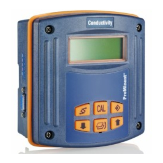
Teil 2: einstellung und bedienung, messgrößen ph/ph (24 Seiten)
Inhaltszusammenfassung für ProMinent DULCOMETER DMT PROFIBUS DP
Seite 1
Supplementary instructions DULCOMETER ® PROFIBUS ® DE/EN/FR/ES A0892 Please carefully read these operating instructions before use! · Do not discard! The operator shall be liable for any damage caused by installation or operating errors! Technical changes reserved. Teile-Nr. 987321 BA DM 212 08/11 ML...
Ergänzungsanleitung DULCOMETER ® mit PROFIBUS ® A0892 Betriebsanleitung bitte zuerst vollständig durchlesen! · Nicht wegwerfen! Bei Schäden durch Installations- oder Bedienfehler haftet der Betreiber! Technische Änderungen vorbehalten!
Seite 6
Ergänzende Anweisungen Allgemeine Gleichbehandlung Dieses Dokument verwendet die nach der Grammatik männliche Form in einem neutralen Sinn, um den Text leichter lesbar zu halten. Es spricht immer Frauen und Männer in gleicher Weise an. Die Leserinnen bitten wir um Verständnis für diese Vereinfachung im Text.
Seite 7
Inhaltsverzeichnis Inhaltsverzeichnis Einstellen / GSD-Datei.................... 8 1.1 Funktionsumfang.................... 8 1.2 Einstellen......................9 Wechseln in den PROFIBUS ® -Mode / Installieren..........11 2.1 Installieren....................13 Funktionen......................17 3.1 Kommunikation im zyklischen Datenverkehr..........17 Index........................28...
Einstellen / GSD-Datei Einstellen / GSD-Datei GSD-Datei GSD-Datei Die GSD-Datei für den DMTa-Mes‐ sumformer kann unter dem folgenden Link geladen werden: http://www.profibus.com/nc/products/ product-guide/product/display/ dulcometer-dmt-transmitters/ Funktionsumfang Der PROFIBUS ® -DMT besitzt den kom‐ pletten Funktionsumfang des Standard-DMT. Der PROFIBUS ® -DMT ist aber ergänzt um die PROFIBUS -DP- ®...
Einstellen / GSD-Datei Einstellen Bei Pausen während dem Einstellen des DMT von > 60 s wird der Einstellvorgang abgebrochen. [Bus-OFF] wie der Standard-DMT einge‐ Der PROFIBUS ® -DMT wird in der Betriebsart [Bus-ON] können Sie stellt, es kommt nur die Busfunktionalität dazu. In der Betriebsart nur die Betriebsart ändern Einstellen der PROFIBUS -Adresse...
Seite 10
Einstellen / GSD-Datei Einstellen der Grenzwerte der Messgröße Das Einstellen der Grenzwerte der Messgröße ist notwendig, damit der DMT Grenz‐ wertüberschreitungen als Fehler an den PROFIBUS ® meldet. Die eingestellten Grenzwerte sind zugleich auch die Werte der Messgröße, bei denen der Ausgangsstrom 4 mA bzw. 20 mA betragen soll Grenzwerte Meßgröße A0894 Abb.
Wechseln in den PROFIBUS®-Mode / Installieren Wechseln in den PROFIBUS -Mode / Installieren ® Wechseln in den PROFIBUS -Mode ® Betriebsart [Bus-ON] Besonderheiten der Betriebsart „Bus-ON“ In der Betriebsart [Bus-ON] ist nur die Betriebsart veränderbar. Beim Umschalten in die Betriebsart [Bus-ON] werden die Einstellungen aus der Betriebsart [Bus-OFF] übernommen.
Seite 12
Wechseln in den PROFIBUS®-Mode / Installieren ð Über den PROFIBUS vor‐ ® genommene Einstellungen werden nicht gespeichert. Es werden wieder die Einstel‐ lungen der Betriebsart [Bus-OFF] geladen.
Wechseln in den PROFIBUS®-Mode / Installieren Installieren Versorgungsspannung DMT anschließen WARNUNG! Maximale Betriebsspannung 30 Volt Ursache: Das Gerät ist nur für Betriebsspannungen ≦ 30 Volt konstruiert. Folge: Tod oder schwerste Verletzungen. Maßnahme: Stellen Sie sicher, dass das Gerät nicht mit Betriebsspannungen > 30 Volt betrieben werden kann.
Seite 14
Wechseln in den PROFIBUS®-Mode / Installieren 9-Pol-D-Sub-Stecker In Deutschland sind diese Steckverbinder in der DIN-Norm DIN 41652 beschrieben, die sich selbst auf MIL-C-24308 und IEC807-2 (Ausgabe 1985) bezieht. Berührungs- und Feuchtigkeitsschutz IP-Einstufung Der PROFIBUS ® -DMT hat eine 9-Pol-D-Sub-Buchse zum Anschluss an ein PRO‐ FIBUS -Kabel.
Seite 15
Wechseln in den PROFIBUS®-Mode / Installieren Führen Sie die Verkabelung wie in Abb. 4 gezeigt durch Y-Adapter (Zubehör Bestell-Nr. 1005838) A0897 Abb. 5: Anschluss-Schema Schirm Txd / Rxd - N (grün) Txd / Rxd - P (rot) Buchse (female) DGND Stecker (male) III.
Seite 16
Wechseln in den PROFIBUS®-Mode / Installieren Abschlussadapter (Zubehör Bestell-Nr. 1005839) A0898 Abb. 6: Anschluss-Schema Schirm Txd / Rxd - N (grün) Txd / Rxd - P (rot) Stecker (male) DGND Schirm Bei Umgebungsbedingungen, die einen Berührungs- und Feuchtigkeitsschutz nach IP 65 erfordern, müssen Sie Kabel mit M12-Industriesteckern und vergossenem 9-Pol-D-Sub- Stecker verwenden.
Funktionen Funktionen Kommunikation im zyklischen Datenverkehr Im zyklischen Telegramm liegen: Alle DMTs Startbyte Datentyp Bezeichner Erklärung Ä „Gerät‐ Byte GerätStatus siehe Tabelle Status“ Tabelle auf Seite 17 float MessWert Byte Messunit pH=0x50, ORP(Redox)=0x52, Cl=0x43, Temp°C=0x54, Temp°F=0x64, Leitf(cond.)=0x4C Byte MessStatus meßwertspezifisch (siehe weiter) Byte Sensortype meßwertspezifisch (siehe weiter)
Seite 18
Funktionen Name Zustand 0 Zustand 1 Warnung keine Warnung Warnung vorhanden – – – – KorrStatus Name Zustand 0 Zustand 1 Korrektur Korrekturwertein‐ automatisch manual gabe Korr.wertüber‐ Wert OK Wert zu hoch schreitung Unterschreitung Wert OK Wert zu niedrig Sensor Sensor OK Sensor defekt Eingang offen...
Seite 19
Funktionen Name Zustand 0 Zustand 1 [MESS_VALUE>MESS_MA Überschreitung keine Grenzw. über‐ schreitung [MESS_VALUE>MESS_MA Unterschreitung keine Grenzw. unter‐ schreitung Sensor defekt Sensorwiderstand < 2 MΩ Eingang offen Kein Fehler Fehlender Sensor Signaleingang Kein Fehler Fehler defekt Temp.bereich des Innerhalb außerhalb (Fehler) Sensors Sensortype Name...
Seite 20
Funktionen Name Zustand 0 Zustand 1 Sensor außer letzte Kalibrierung OK Kalibrierung nicht möglich Kalibrierbereich immer DMT-Redox(ORP) MessStatus Name Zustand 0 Zustand 1 Messwert gültig ungültig Temperaturkor‐ rektur Überschreitung keine Grenzw. über‐ MESS_VALUE> schreitung MESS_MAX Unterschreitung keine Grenz. unterschrei‐ MESS_VALUE< tung MESS_MIN Sensor defekt...
Seite 21
Funktionen Name Zustand 0 Zustand 1 Sensor außer Kalib‐ Sensor OK Abweichung zur Pufferlö‐ rierbereich sung >40mV immer DMT-Cl MessStatus Name Zustand 0 Zustand 1 Messwert gültig ungültig Temperaturkorrektur ON [MESS_VALUE>MESS_M Überschreitung keine Grenzw. über‐ schreitung [MESS_VALUE>MESS_M Unterschreitung keine Grenzw. unter‐ schreitung immer Sensorsignal zu...
Seite 22
Funktionen Sensorquality Name Zustand 0 Zustand 1 Steilheit untere > 25 % (OK) 10 ÷ 25 % Grenze Steilheit obere < 400 % (OK) 400 ÷ 1000 % Grenze immer Einstellzeit OK (< 60 s) zu lang (> 60 s) Sensor außer Kalib‐...
Seite 23
Funktionen Sensortype Name Wert Pt100 0x48 Pt1000 0x54 [Sensorqualitiy] entfällt, da ohne Bedeutung für [Temp] DMT-Leitfähigkeit MessStatus Name Zustand 0 Zustand 1 Messwert gültig ungültig Temperaturkorrektur [MESS_VALUE>MES Überschreitung keine Grenzw.überschrei‐ S_MAX] tung [MESS_VALUE<MES Unterschreitung keine Grenz. unterschrei‐ S_MIN] tung immer Eingang offen Kein Fehler Fehlender Sernsor...
Seite 24
Funktionen Name Wert Zellkonst = 0,01 Zellkonst = 10 [Sensorqualitiy] entfällt, da ohne Bedeutung für Leitfähigkeit...
Seite 25
Funktionen Diagnosetelegramme [Get_Sl_Diag] zur Verfügung. Der DMT stellt Ihnen gemäß PROFIBUS -Norm den Dienst ® Die Diagnosedaten bestehen aus Standarddiagnose-Informationen (6-Bytes gemäß PROFIBUS ® -Norm) und eventuell gerätespezifischen Diagnosedaten. Für die gerätespe‐ zifischen Diagnosedaten können maximal 63 Byte eingefügt werden. Hiervon sind die ersten 4 Byte in der PROFIBUS ®...
Seite 26
Funktionen [user_data -Felder] werden Fehler signalisiert. Die [user_data -Felder] sind in Über die Blocks von je 3 Byte zusammengefasst und wie folgt zu interpretieren: Dienst Fehlerart Art des Datenzugriffs (lesen/schreiben) Somit können bis zu 19 Fehler signalisiert werden. Kodierung user_data Dienste Index Bezeichner...
Supplementary instructions DULCOMETER ® with PROFIBUS ® A0892 Please carefully read these operating instructions before use! · Do not discard! The operator shall be liable for any damage caused by installation or operating errors! Technical changes reserved.
Seite 31
Supplemental instructions General non-discriminatory approach In order to make it easier to read, this document uses the male form in grammat‐ ical structures but with an implied neutral sense. It is aimed equally at both men and women. We kindly ask female readers for their understanding in this simplification of the text.
Seite 33
Table of contents Table of contents Settings / GSD file....................34 1.1 Functional scope..................34 1.2 Adjustment....................35 Change to PROFIBUS ® mode / install..............37 2.1 Installation....................39 Functions......................43 3.1 Communication in cyclic data traffic............. 43 Index........................54...
Settings / GSD file Settings / GSD file GSD file GSD file The GSD file for the DMTa measuring transducer can be loaded from the fol‐ lowing link: http://www.profibus.com/nc/products/ product-guide/product/display/ dulcometer-dmt-transmitters/ Functional scope The PROFIBUS ® -DMT has the complete range of functions of the Standard-DMT.
Settings / GSD file Adjustment The setting process is cancelled if during setting of the DMT no entries are made for > 60 s. [Bus-OFF] analogously to the The PROFIBUS ® -DMT is ajdusted in operating mode standard DMT, only bus functionality is added. You can only change the operating mode [Bus-ON] operating mode Setting the PROFIBUS address...
Seite 36
Settings / GSD file Setting the measured variable limit values Setting the limit values of the measured variable is necessary so that the exceeding of the limit values by the DMT is reported as an error on the PROFIBUS ® The set limit values are also the values of the measured variables, at which the output current should equal 4 mA or 20 mA min.
Change to PROFIBUS® mode / install Change to PROFIBUS mode / install ® Change to PROFIBUS mode ® Operating mode [Bus-ON] Details of operating mode "Bus-ON" In [Bus-ON] operating mode, it is only possible to change the operating mode. The settings from [Bus-OFF] operating mode are adopted when switching to operating mode [Bus-ON].
Seite 38
Change to PROFIBUS® mode / install ð Settings made over the PROFIBUS ® are not saved. The settings of operating mode [Bus-OFF] are reloaded.
Change to PROFIBUS® mode / install Installation Connect the DMT supply voltage WARNING! Maximum operating voltage 30 volts Cause: The device is only designed for use with operating voltages ≦ 30 volts Consequence: Fatal or very serious injuries. Measure: Ensure that the device cannot be operated with operating voltages > 30 V. The system operator is responsible for ensuring this.
Seite 40
Change to PROFIBUS® mode / install Contact and humidity protection; IP rating The PROFIBUS DMT has a 9-pin D-sub socket for connection to a PROFIBUS ® ® cable. The pin allocation corresponds to the PROFIBUS standard (see below), so ® that standard bus connectors can be used.
Seite 41
Change to PROFIBUS® mode / install Y-adapter (accessory part no. 1005838) A0897 Fig. 5: Connection diagram Shielding Txd / Rxd - N (green) Txd / Rxd - P (red) Socket (female) DGND Plug (male) III. Shielding For ambient conditions which require contact and moisture protection conforming to IP 65, you must use a cable with M12 industrial connectors and a moulded 9-pin D-sub plug.
Seite 42
Change to PROFIBUS® mode / install For ambient conditions which require contact and moisture protection conforming to IP 65, you must use a cable with M12 industrial connectors and a moulded 9-pin D-sub plug. If the DMT is the last bus member connected to the PROFIBUS ®...
Functions Functions Communication in cyclic data traffic The cyclic data frame comprises: All DMTs Start byte Data type Identifiers Explanation Ä “Device status” Table Byte Device status See table on page 43 Float MeasValue Byte Measurement pH=0x50, ORP(Redox)=0x52, unit Cl=0x43, Temp°C=0x54, Temp°F=0x64, Conductivity=0x4C Byte...
Seite 44
Functions Name Status 0 Status 1 Error No error No error present Warning No warning Warning present – – – – CorrStatus Name Status 0 Status 1 Correction Correction value is connected manual input Corr.value Value OK Value too high exceeded Undershoot Value OK...
Seite 45
Functions DMT-pH MeasStatus Name Status 0 Status 1 Measured value Valid Invalid Temperature cor‐ rection [MEAS_VALUE>MEAS_MA Overshoot No limit value overshoot [MEAS_VALUE>MEAS_MA Undershoot No limit value under‐ shoot Sensor defective Sensor resistance < 2 MΩ Input open No error Sensor missing Signal input defec‐...
Seite 46
Functions Name Status 0 Status 1 Zero point upper < 50 mV (OK) 50 ÷ 60 mV limit Adjustment time OK (< 60 s) too long (> 60 s) Sensor outside cal‐ Last calibration OK Calibration not possible ibration range Always DMT-Redox(ORP) MeasStatus...
Seite 47
Functions Name Status 0 Status 1 Sensor outside cali‐ Sensor OK Deviation from the buffer bration range solution >40mV Always DMT-Cl MeasStatus Name Status 0 Status 1 Measured value Valid Invalid Temperature correc‐ tion [MEAS_VALUE>MEAS_M Overshoot No limit value overshoot [MEAS_VALUE>MEAS_M Undershoot No limit value under‐...
Seite 48
Functions Sensor quality Name Status 0 Status 1 Slope lower limit > 25 % (OK) 10 ÷ 25 % Slope upper limit < 400 % (OK) 400 ÷ 1000 % Always Adjustment time OK (< 60 s) too long (> 60 s) Sensor outside cali‐...
Seite 49
Functions Sensor type Name Value Pt100 sensor 0x48 Pt1000 0x54 [Sensor quality] not needed, as no meaning for [temp] DMT-conductivity MeasStatus Name Status 0 Status 1 Measured value Valid Invalid Temperature correc‐ tion [MEAS_VALUE>MEA Overshoot No limit valve overshoot S_MAX] [MEAS_VALUE<...
Seite 50
Functions Name Value Cell constant = 0.01 Cell constant = 10 [Sensor quality] not needed, as no meaning for conductivity...
Seite 51
Functions Diagnostics frame In accordance with the PROFIBUS standard, the DMT provides you with the ® [Get_Sl_Diag] service. The diagnostics data comprise standard diagnostics information (6 bytes according to the PROFIBUS ® standard) and possibly device-specific diagnostics data. A maximum of 63 bytes can be inserted for the device-specific diagnostics data. Of which the first 4 bytes are specified in the PROFIBUS ®...
Seite 52
Functions [user_data fields] are used to signal errors. The [user_data fields] are each combined in blocks of 3 bytes and are interpreted as follows: Service Error type Type of data access (read/write) Thus up to 19 errors can be signalled. Encoding user_data Service Index...
Seite 53
Functions Index Identifiers Explanation [CorrMax] 0x 11 Temperature lower limit value [CorrSensortype] 0x 12 See cyclic data traffic [DeviceId] 0x 13 Device identity code [DeviceSerNum] 0x 14 Serial number [SoftRev] 0x 15 Software version number [HardRev] 0x 16 Hardware version number...
Index Index 1, 2, 3 ... 9-pin D-sub plug........39 IP 20............. 39 IP 65............. 39 Ambient conditions,......41 IP rating..........39 Connect the DMT supply voltage..39 Maximum operating voltage 30 volts. . . 39 Connect the supply voltage gateway... 39 Cyclic data traffic........
Instructions complémentaires DULCOMETER ® avec PROFIBUS ® A0892 Veuillez commencer par lire l’intégralité du mode d’emploi ! · Toujours conserver ce document ! L’exploitant est personnellement responsable en cas de dommages dus à des erreurs de com‐ mande ou d’installation ! Sous réserve de modifications techniques.
Seite 57
Instructions complémentaires Principe d'égalité Le présent document utilise la forme mas‐ culine selon les règles de la grammaire au sens neutre, afin de simplifier la lecture de ce texte. Il s'applique toujours de même aux femmes et aux hommes. Nous remer‐ cions les lectrices de bien vouloir com‐...
Seite 59
Table des matières Table des matières Réglage / Fichier GSD..................60 1.1 Étendue des fonctions.................. 60 1.2 Réglage......................61 Passer dans le mode PROFIBUS ® / Installation........... 63 2.1 Installation....................65 Fonctions......................69 3.1 Communication en échange cyclique de données........69 Index........................
Réglage / Fichier GSD Réglage / Fichier GSD Fichier GSD Fichier GSD Le fichier GSD pour les convertis‐ seurs de mesure DMTa peut être télé‐ chargé au moyen du lien suivant : http://www.profibus.com/nc/products/ product-guide/product/display/ dulcometer-dmt-transmitters/ Étendue des fonctions Le PROFIBUS ®...
Réglage / Fichier GSD Réglage Le processus de réglage est interrompu si des pauses de plus de 60 secondes sont constatées pendant le réglage du DMT. [Bus-OFF] comme le DMT Le PROFIBUS ® DMT est réglé en mode de fonctionnement standard ;...
Seite 62
Réglage / Fichier GSD Réglage des valeurs limites pour les grandeurs mesurées Des valeurs limites doivent être réglées pour les grandeurs mesurées afin que le DMT signale le dépassement de ces valeurs limites comme des erreurs au PROFIBUS ® En outre, les valeurs limites réglées correspondent aussi aux valeurs des grandeurs mesurées pour lesquelles le courant de sortie doit s'élever à...
Passer dans le mode PROFIBUS® / Installation Passer dans le mode PROFIBUS / Installation ® Passer dans le mode PROFIBUS ® Mode de fonctionnement [Bus-ON] Particularités du mode de fonctionnement « Bus-ON » En mode de fonctionnement [Bus-ON], seul le mode de fonctionnement peut être modifié.
Seite 64
Passer dans le mode PROFIBUS® / Installation ð Les réglages effectués via le PROFIBUS ® ne sont pas enregistrés. Les réglages du mode de fonc‐ [Bus-OFF] sont à tionnement nouveau chargés.
Passer dans le mode PROFIBUS® / Installation Installation Assurer l'alimentation du DMT AVERTISSEMENT ! Tension de service maximale 30 Volt Cause : L'appareil n'est conçu que pour des tensions de service ≦ 30 Volt. Conséquence : Mort ou blessures extrêmement graves. Remède : Assurez-vous que l'appareil ne peut être utilisé...
Seite 66
Passer dans le mode PROFIBUS® / Installation Prise D-Sub à 9 pôles En Allemagne, ces connecteurs sont décrits dans la norme DIN 41652 qui se réfère elle-même aux normes MIL-C-24308 et IEC807-2 (édition 1985). Protection contre les contacts et contre l’humidité, classement IP Le PROFIBUS ®...
Seite 67
Passer dans le mode PROFIBUS® / Installation Réalisez le câblage conformément au Ill. 4 Adaptateur en Y (accessoire, réf. 1005838) A0897 Ill. 5: Schéma de connexion Blindage Txd / Rxd - N (vert) Txd / Rxd - P (rouge) Prise (femelle) DGND Fiche (mâle) III.
Seite 68
Passer dans le mode PROFIBUS® / Installation Adaptateur de terminaison (accessoire, réf. 1005839) A0898 Ill. 6: Schéma de connexion Blindage Txd / Rxd - N (vert) Txd / Rxd - P (rouge) Fiche (mâle) DGND Blindage Si les conditions ambiantes requièrent une protection contre les contacts et contre l'humi‐ dité...
Fonctions Fonctions Communication en échange cyclique de données Le télégramme cyclique comprend : Tous les DMT Octet de Type de Affichage Explication départ données Ä »État appareil Octet État appareil Voir tableau « Tableau à la page 70 Flottante Valeur mesurée Octet Unité...
Seite 70
Fonctions État appareil Pos. État 0 État 1 Mode PRO‐ Bus-ON Bus-OFF FIBUS® Initialisation État de fonctionnement DMT en état d'initialisation Erreur Pas d'erreur Erreur présente Avertissement Pas d'avertissement Avertissement présent – – – – État corr. Pos. État 0 État 1 Correction Entrée valeur de...
Seite 71
Fonctions DMT-pH État mesure Pos. État 0 État 1 Valeur mesurée Valide Invalide Correction de la température [MESS_VALUE>MESS_MA Dépassement Pas de dépassement de valeur limite [MESS_VALUE>MESS_MA Sous-dépasse‐ Pas de sous-dépasse‐ ment ment de valeur limite Capteur défec‐ Résistance du capteur < 2 tueux MΩ...
Seite 73
Fonctions Pos. État 0 État 1 Toujours Toujours [Type de capteur] Inutile car sans importance pour le redox(ORP) État mesure Pos. État 0 État 1 Toujours Résistance du cap‐ OK (>2 MΩ) Capteur défectueux (<2 teur MΩ) Capteur en dehors Capteur OK Écart par rapport à...
Seite 74
Fonctions Pos. État 0 État 1 Signal de capteur Pas d'erreur < -100 mV trop faible Plage de temp. du Dans la plage En dehors (erreur) capteur Type de capteur Valeur CLE 5ppm CTE 10ppm CLE 50ppm Qualité capteur Pos. État 0 État 1 Pente limite infé‐...
Seite 75
Fonctions DMT-Temp État mesure Pos. État 0 État 1 Valeur mesurée Valide Invalide Toujours [MESS_VALUE>MESS Dépassement Pas de dépassement de _MAX] valeur limite [MESS_VALUE<MESS Sous-dépassement Pas de sous-dépasse‐ _MIN] ment de valeur limite Capteur défectueux Pas d'erreur Erreur présente Entrée ouverte Pas d'erreur Erreur présente Court-circuit entrée...
Seite 76
Fonctions Pos. État 0 État 1 [MESS_VALUE>MES Dépassement Pas de dépassement de S_MAX] valeur limite [MESS_VALUE<MES Sous-dépassement Pas de sous-dépassement S_MIN] de valeur limite Toujours Entrée ouverte Pas d'erreur Capteur défectueux Court-circuit entrée Pas d'erreur Résistance du capteur ≅ 0 Ω Plage de temp.
Seite 77
Fonctions Télégrammes de diagnostic [Get_Sl_Diag] . Les don‐ Le DMT respecte la norme PROFIBUS pour fournir le service ® nées de diagnostic sont composées d’informations de diagnostic standard (6 octets con‐ formément à la norme PROFIBUS ® ) et éventuellement de données de diagnostic spécifi‐ ques à...
Seite 78
Fonctions II.I Type d'état : 48 (spécifique au fabri‐ cant) [champs user_data] . Les [champs user_data] sont ras‐ Les erreurs sont signalées via les semblés en blocs de 3 octets chacun et doivent être interprétés de la manière suivante : Service Type d’erreur Type d'accès aux données (lecture/écriture)
Seite 79
Fonctions Index Affichage Explication [État corr.] 0x 0F Voir échange cyclique de données [Corr. min.] 0x 10 Valeur limite inférieure de température [Corr. max.] 0x 11 Valeur limite inférieure de température [Corr. type de capteur] 0x 12 Voir échange cyclique de données [Id.
Index Index IP 65............. 65 Adaptateur de terminaison ....68 Adaptateur en Y ........67 Principe d'égalité........57 Assurer l'alimentation de la passerelle 65 Prise D-Sub à 9 pôles......65 Assurer l'alimentation du DMT..... 65 Autres documents applicables..... 60 Réglage de l'adresse PROFIBUS..61 Réglage des valeurs limites pour les grandeurs mesurées......
Manual complementario DMT DULCOMETER ® con DP PROFIBUS ® A0892 ¡Lea primero las instrucciones de servicio completas! · ¡No las tire! ¡En caso de daños debidos a errores de instalación o manejo, será responsable el propio usuario! Reservadas modificaciones técnicas.
Seite 83
Instrucciones complementarias Igualdad de trato general Este documento emplea la forma gramá‐ tica masculina en sentido neutro para faci‐ litar la lectura del texto. Se refiere siempre a mujeres y hombres de igual modo. Pedimos a las lectoras que comprendan esta simplificación del texto.
Seite 85
Índice de contenido Índice de contenido Ajuste / Archivo GSD.................... 86 1.1 Funciones..................... 86 1.2 Ajuste......................87 Cambio al modo PROFIBUS ® / Instalación............89 2.1 Instalación....................91 Funciones......................95 3.1 Comunicación en transporte de datos cíclico..........95 Índice........................106...
Ajuste / Archivo GSD Ajuste / Archivo GSD Archivo GSD Archivo GSD El archivo GSD para el convertidor de medición DMTa se puede descargar, por ejemplo, a través del siguiente enlace: http://www.profibus.com/nc/products/ product-guide/product/display/ dulcometer-dmt-transmitters/ Funciones El DMT PROFIBUS incluye todas las ®...
Ajuste / Archivo GSD Ajuste Si durante el ajuste del DMT se realizan pausas de más de 60 s, se interrumpe el proceso de ajuste. [Bus-OFF] como el DMT El DMT PROFIBUS ® se ajusta en el modo de funcionamiento [Bus-ON] estándar, solo se suman las funciones Bus.
Seite 88
Ajuste / Archivo GSD Ajuste de los valores límite de la magnitud de medida Es necesario ajustar los valores límite de la magnitud de medida para que el DMT notifique las infracciones de dichos valores como errores en el PROFIBUS ®...
Cambio al modo PROFIBUS® / Instalación Cambio al modo PROFIBUS / Instalación ® Cambio al modo PROFIBUS ® Modo de funcionamiento [Bus-ON] Peculiaridades del modo de funcionamiento "Bus-ON“ En el modo de funcionamiento [Bus-ON] solo se puede modificar el modo de funcio‐ namiento.
Seite 90
Cambio al modo PROFIBUS® / Instalación ð Los ajustes realizados a través del PROFIBUS ® se guardan. Se cargan de nuevo los ajustes del modo de funcionamiento [Bus-OFF] .
Cambio al modo PROFIBUS® / Instalación Instalación Conectar la tensión de alimentación del DMT ¡ADVERTENCIA! Tensión de servicio máxima 30 voltios Causa: El aparato solo está diseñado para tensiones de servicio ≦ 30 voltios. Consecuencia: muerte o lesiones muy graves. Medida: Asegúrese de que el aparato no se pone en funcionamiento con tensiones de servicio >...
Seite 92
Cambio al modo PROFIBUS® / Instalación Conector tipo D-Sub de 9 polos En Alemania, estos conectores enchufables aparecen descritos en la norma DIN 41652, relativa a MIL-C-24308 e IEC807-2 (edición de 1985). Clasificación IP de la protección contra contacto y humedad El DMT PROFIBUS ®...
Seite 93
Cambio al modo PROFIBUS® / Instalación Realice el cableado tal y como se muestra en Fig. 4 Adaptador Y (n.º de referencia de accesorio 1005838) A0897 Fig. 5: Esquema de conexión Pantalla Txd / Rxd - N (verde) Txd / Rxd - P (rojo) Clavija (hembra) DGND Conector (macho)
Seite 94
Cambio al modo PROFIBUS® / Instalación Adaptador terminal (n.º de referencia de accesorio 1005839) A0898 Fig. 6: Esquema de conexión Pantalla Txd / Rxd - N (verde) Txd / Rxd - P (rojo) Conector (macho) DGND Pantalla En condiciones ambientales que requieran una protección contra contacto y humedad según IP 65, utilice cables con enchufes industriales M12 y conectores D-Sub de 9 polos encapsulados.
Funciones Funciones Comunicación en transporte de datos cíclico El telegrama cíclico incluye: Todos los DMT Byte inicial Tipo de Indicador Explicación datos Ä »Estado del apa‐ Byte Estado del véase la tabla aparato rato« Tabla en la página 96 float Valor medido Byte Unidad de...
Seite 96
Funciones Estado del aparato Nombre Estado 0 Estado 1 Modo PRO‐ Bus-ON Bus-OFF FIBUS® Inicialización Estado de funciona‐ DMT en estado inicial miento Error Ningún error Errores presentes Advertencia Ninguna advertencia Hay advertencias – – – – Estado de corrección Nombre Estado 0 Estado 1...
Seite 97
Funciones Nombre Estado 0 Estado 1 Entrada cortocir‐ Entrada correcta Entrada cortocircuitada cuitada DMT-pH Estado de medición Nombre Estado 0 Estado 1 Valor medido válido no válido Corrección de tem‐ peratura [MESS_VALUE>MESS_MA Diferencia exce‐ sin superación de valor dida límite [MESS_VALUE>MESS_MA Diferencia insufi‐...
Seite 98
Funciones Calidad del sensor Nombre Estado 0 Estado 1 Pendiente dema‐ > 45 mV/pH (OK) 40 ÷ 45 mV/pH siado alta Pendiente, límite < 63 mV/pH (OK) 63 ÷ 65 mV/pH superior Punto cero, límite > -50 mV (OK) -60 ÷ -50 mV inferior Punto cero, límite <...
Seite 99
Funciones Nombre Estado 0 Estado 1 siempre siempre [Tipo de sensor] no está presente, ya que no es relevante para Redox(redx) Estado de medición Nombre Estado 0 Estado 1 siempre Resistencia del correcta (>2 MΩ) Sensor defectuoso (<2 sensor MΩ) Sensor fuera del Sensor correcto Desviación de solución...
Seite 100
Funciones Nombre Estado 0 Estado 1 Señal de sensor Ningún error <-100 mV demasiado baja Rango de tempera‐ Dentro Fuera (error) tura del sensor Tipo de sensor Nombre Valor CLE 5ppm CTE 10ppm CLE 50ppm Calidad del sensor Nombre Estado 0 Estado 1 Pendiente dema‐...
Seite 101
Funciones Temp. DMT Estado de medición Nombre Estado 0 Estado 1 Valor medido válido no válido siempre [MESS_VALUE>MESS Diferencia excedida Sin superación del valor _MAX] límite [MESS_VALUE<MESS Diferencia insufi‐ sin valor límite insufi‐ _MIN] ciente ciente Sensor defectuoso Ningún error Errores presentes Entrada abierta Ningún error...
Seite 102
Funciones Nombre Estado 0 Estado 1 [MESS_VALUE>MES Diferencia excedida Sin superación del valor S_MAX] límite [MESS_VALUE<MES Diferencia insufi‐ sin valor límite insuficiente S_MIN] ciente siempre Entrada abierta Ningún error Sensor defectuoso Entrada cortocircui‐ Ningún error Resistencia del tada sensor ≅ 0 Ω Rango de tempera‐...
Seite 103
Funciones Telegramas de diagnóstico [Get_Sl_Diag] . Los datos de El DMT ofrece, según la norma PROFIBUS , el servicio ® diagnóstico incluyen información de diagnóstico estándar (6 bytes, según la norma PRO‐ FIBUS ® ) y, en su caso, datos de diagnóstico específicos del aparato. Para los datos de diagnóstico específicos del aparato se pueden añadir un máximo de 63 bytes.
Seite 104
Funciones II.I Tipo de estado: 48 (específico del fabricante) [campos user_data] se señalizan los errores. Los [campos user_data] se Mediante los dividen en bloques de 3 bytes cada uno, y se interpretan de la siguiente forma: Servicio Tipo de error Tipo de acceso de datos (lectura/escritura) De esta forma se pueden señalizar hasta 19 errores.
Seite 105
Funciones Índice Indicador Explicación [Estado de corrección] 0x 0F véase Transporte de datos cíclico [CorrMín] 0x 10 Valor límite inferior, temperatura [CorrMáx] 0x 11 Valor límite inferior, temperatura [TipoSensorCorr] 0x 12 véase Transporte de datos cíclico [IdAparato] 0x 13 Código de identificación (Ident-code) del aparato [NúmSerAparato] 0x 14 Número de serie...
Índice Índice Adaptador terminal ......94 Igualdad de trato........83 Adaptador Y ........93 Igualdad de trato general..... 83 Ajuste de la dirección PROFIBUS..87 Información relativa al aparato... 103 Ajuste de los valores límite de la IP 20............. 91 magnitud de medida......