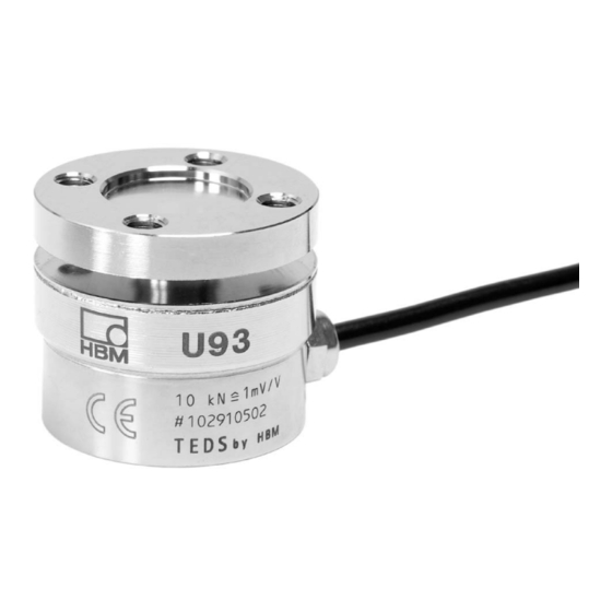
HBM U93 series Montageanleitung
Kraftaufnehmer
Vorschau ausblenden
Andere Handbücher für U93 series:
- Montageanleitung (64 Seiten) ,
- Montageanleitung (88 Seiten)

Verwandte Anleitungen für HBM U93 series


Inhaltszusammenfassung für HBM U93 series
- Seite 1 Mounting instructions Montageanleitung Notice de montage Force transducer Kraftaufnehmer Capteur de force A2081-2.1 en/de/fr...
- Seite 2 English ..........Seite 3 −...
- Seite 19 Inhalt Seite Sicherheitshinweise ..........Lieferumfang .
-
Seite 20: Sicherheitshinweise
Sicherheitshinweise Bestimmungsgemäßer Gebrauch Die Kraftaufnehmer der Typenreihe U93 sind für Kraftmessungen in Prüfstän- den/Einpressvorrichtungen/Prüfvorrichtungen/Pressen vorgesehen. Jeder darüber hinausgehende Gebrauch gilt als nicht bestimmungsgemäß. Zur Gewährleistung eines sicheren Betriebes darf der Aufnehmer nur nach den Angaben in der Montageanleitung verwendet werden. Bei der Verwen- dung sind zusätzlich die für den jeweiligen Anwendungsfall erforderlichen Rechts- und Sicherheitsvorschriften zu beachten. - Seite 21 Weist darauf hin, dass wichtige Informationen über das Produkt oder über die Handhabung des Produktes gegeben werden. Symbol: Bedeutung: CE-Kennzeichnung Mit der CE-Kennzeichnung garantiert der Hersteller, dass sein Produkt den Anforderungen der relevanten EG-Richtlinien entspricht (die Konformitätser- klärung finden Sie unter http://www.hbm.com/HBMdoc). A2081-2.1 en/de/fr...
-
Seite 22: Wartung
Umbauten und Veränderungen Der Aufnehmer darf ohne unsere ausdrückliche Zustimmung weder konstruk- tiv noch sicherheitstechnisch verändert werden. Jede Veränderung schließt eine Haftung unsererseits für daraus resultierende Schäden aus. Ausgenom- men hiervon sind Montage und Demontage des Adapters nach Kapitel 4. Qualifiziertes Personal Dieses Gerät ist nur von qualifiziertem Personal ausschließlich entsprechend der technischen Daten in Zusammenhang mit den nachstehend ausgeführten... -
Seite 23: Lieferumfang
Lieferumfang • Kraftaufnehmer U93 • Bedienungsanleitung U93 Anwendungshinweise Die Kraftaufnehmer der Typenreihe U93 sind für Messungen von Zug- und Druckkräften geeignet. Sie messen statische und dynamische Kräfte mit ho- her Genauigkeit und verlangen daher eine umsichtige Handhabung. Beson- dere Aufmerksamkeit erfordern hierbei Transport und Einbau der Geräte. Stöße oder Stürze können zu permanenten Schäden am Aufnehmer führen. -
Seite 24: Bedingungen Am Einsatzort
Bedingungen am Einsatzort 3.1 Umgebungstemperatur Die Temperatureinflüsse auf das Nullsignal sowie auf den Kennwert sind kom- pensiert. Um optimale Messergebnisse zu erzielen, ist der Nenntemperaturbereich einzuhalten. Temperaturbedingte Messfehler entste- hen durch einseitige Erwärmung (z. B. Strahlungswärme) oder Abkühlung. Ein Strahlungsschild und allseitige Wärmedämmung bewirken merkliche Verbes- serungen, dürfen aber keinen Kraftnebenschluss bilden. -
Seite 25: Mechanischer Einbau
• Aufnehmer nicht überlasten. • Der Aufnehmer sollte schon bei oder unmittelbar nach dem Einbau durch eine Kupferlitze 50 mm (hochflexible Erdungskabel EEK aus dem HBM Lieferprogramm) überbrückt sein. Das Kabel wird oberhalb und unterhalb des Aufnehmers angeschraubt. Dadurch wird verhindert, dass Schweiß- ströme über den Aufnehmer fließen und den Krafteinleitungspunkt ver-... -
Seite 26: Einbau Für Zugbelastung/Druckbelastung
4.3 Einbau für Zugbelastung/Druckbelastung Der Aufnehmer wird direkt (über die ringförmigen Flanschflächen) an ein stei- fes voll tragendes Konstruktionselement (z.B. Profil, Decke, Platte) ge- schraubt. Bei dieser Einbauart können die Aufnehmer axiale Kräfte in Zug- und in Druckrichtung messen. Auch Wechsellasten werden einwandfrei er- fasst. -
Seite 27: Elektrischer Anschluss
Elektrischer Anschluss Die Aufnehmer werden standardmäßig mit einem 3 m langen Kabel mit freien Enden geliefert. Der Kabelschirm ist vollflächig an das Aufnehmergehäuse angeschlossen. Dadurch wird das Messsystem von einem Faradayschen Kä- fig umschlossen, elektromagnetische Störungen beeinflussen das Messsy- stem nicht. HINWEIS: Wird bei Druckbelastung des Aufnehmers eine negative Aus- gangsspannung am Messverstärker gewünscht, müssen die... -
Seite 28: Hinweise Für Die Verkabelung
5.1 Hinweise für die Verkabelung • Verwenden Sie nur abgeschirmte und kapazitätsarme Messkabel von HBM. • Messkabel nicht parallel zu Starkstrom- oder Steuerleitungen verlegen. Falls dies nicht möglich ist (z. B. in Kabelschächten), schützen Sie das Messkabel z. B. durch Stahlpanzerrohre und halten einen Mindestabstand von 50 cm zu den anderen Kabeln. -
Seite 29: Aufnehmer-Identifikation Teds
Am Anschluss grau (gegen Masse an schwarz) steht ein digitales Identifikati- onssystem zur Verfügung. Basis ist ein 1−Wire EEPROM DS2433 der Fa. Ma- xim/Dallas. Zum Einspeichern der Daten stellt HBM den TEDS-Editor zur Verfügung. Dieser ist Bestandteil der Software MGCplus-Setup-Assistent (siehe TEDS- Bedienunganleitung “TEDS-Datenspeicher im Aufnehmer” auf der Internet- seite www.hbm.com/TEDS). - Seite 30 Für den Kraftaufnehmer U93 hat HBM bereits das Template Bridge Sensor beschrieben. Bereich 4: Der letzte Bereich kann vom Anwender selbst verändert werden, z.B. mit − Kanalname, − Filtereinstellungen, − Nullwert Beispiel: Von HBM auf Basis des individuellen Prüfprotokolls beschriebener Inhalt: Be- reich 3 des Sensors U93/2 kN mit der Ident-Nr.
- Seite 31 ”mV/V” und ”μV/V” für die Genauigkeit der in TEDS abgebildeten Aufnehmer- kennlinie zu wählen. HBM wählt hier stets ”Full Precision” um die volle digitale Auflösung nutzen zu können. Diese Wahl wird auch Anwendern empfohlen, die den TEDS− Speicher selbst programmieren.
-
Seite 32: Technische Daten (Vdi/Vde2638)
Technische Daten (VDI/VDE2638) Nennkraft Nennkennwert mV/V Rel. Kennwertabweichung (Druck) <"0,5 mV/V <"0,075 Rel. Abweichung des Nullsignals Relative Umkehrspanne (0,5 F ν <"0,5 bis F Rel. Linearitätsabweichung <"0,5 Druck Temperatureinfluss auf den Kennwert/10 K <"0,5 bezogen auf den Nennkennwert Temperatureinfluss auf das Null- signal/10 K bezogen auf den Nennkennwert <... -
Seite 33: Abmessungen
Abmessungen ∅A ∅C Mini-Verschraubung M8x1 ∅C ∅B *) nutzbare Zentriertiefe U93/1 kN ... 10 kN U93/20 kN ... 50 kN ca. 10 ca. 5 ca. 5 8 x 45 ca. 10 4 x 90 22,5 ∅K ∅K " 0,1 Nennkraft ∅A ∅B ∅C... -
Seite 34: Optionen
Optionen U93-Kraftaufnehmer, optionale Ausführungen Code Nennkraft 1K00 2K00 5K00 10K0 10kN 20K0 20kN Vorzugsausführung 50K0 50kN kurzfristig lieferbar Code Kabellänge Code Kabelausführung freie Enden 15pol. D-Stecker Stecker MS3106PEMV − − K−U93 − 2K00 A2081-2.1 en/de/fr... - Seite 51 A2081-2.1 en/de/fr...
- Seite 52 Hottinger Baldwin Messtechnik GmbH 7−2001.2081 Postfach 10 01 51, D-64201 Darmstadt Im Tiefen See 45, D-64293 Darmstadt Tel.: +49 6151 803-0 Fax: +49 6151 8039100 Email: support@hbm.com Internet: www.hbm.com A2081-2.1 en/de/fr...