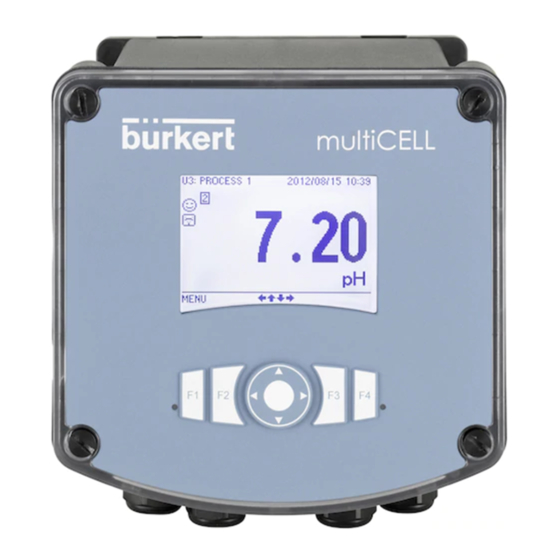
bürkert 8619 Montageblatt
Vorschau ausblenden
Andere Handbücher für 8619:
- Bedienungsanleitung (210 Seiten) ,
- Schnellstartanleitung (56 Seiten) ,
- Bedienungsanleitung (218 Seiten)
Werbung
Verfügbare Sprachen
Verfügbare Sprachen
Quicklinks
Type 8619
Assembly instructions
Montageblatt
1410/0_EU-ML_00566607
assembly kit 00564596 — assembly instructions of the
kit and set up instructions of the 8619
NOTE
Risk of material damage if the cable glands of the 8619 are loose. The body of the cable glands are screwed into the
housing at the factory with a torque of 5.5 Nm
• Before installing the housing on the pipe, check that the bodies of the cable glands are tightened. If the bodies of the cable
glands are loose, tighten them with a torque of 5.5 Nm ± 20 %.
The assembly kit allows you to install the 8619, wall-mounting versions, on horizontal or vertical pipes whith an external dia-
meter comprised between 30 mm and 110 mm.
→
Choose a location such that:
• The surface temperature of the pipe remains below 100°C.
• The display is at eye level.
• There is sufficient space to open the housing by 180°.
1
fastening plate
90 mm
135 mm
3
2
fastening brackets
90 mm
135 mm
Step 1: Remove the fastening plate from the device.
→
Press the tab to unlock the device.
→
Lift the device.
→
Separate the device from the fastening plate.
Step 2 for an horizontal pipe: Mount the 2 assembly
kits.
→
Insert the 4 screws in the holes drilled in the fastening
plate.
→
Insert each fastening bracket in 2 screws.
→
Respect the 90 mm distance between two screws,
as shown in the drawing on the left.
→
Insert a locking-washer and a nut on each screw.
→
Tighten the 4 screws with a maximum torque of
5.3 Nm.
Step 2 for a vertical pipe: Mount the 2 assembly kits.
→
Insert the 4 screws in the holes drilled in the fastening
plate.
→
Insert each fastening bracket in 2 screws.
→
Respect the 135 mm distance between two screws,
as shown in the drawing on the left.
→
Insert a locking-washer and a nut on each screw.
→
Tighten the 4 screws with a maximum torque of
5.3 Nm.
Werbung

Inhaltszusammenfassung für bürkert 8619
- Seite 1 8619 NOTE Risk of material damage if the cable glands of the 8619 are loose. The body of the cable glands are screwed into the housing at the factory with a torque of 5.5 Nm • Before installing the housing on the pipe, check that the bodies of the cable glands are tightened. If the bodies of the cable...
- Seite 2 Type 8619 Assembly instructions Instructions d’assemblage 1410/0_EU-ML_00566607 Step 3: Install the assembly kit on the pipe. → Set the fastening plate on both sides of the pipe placing the tab at the bottom. → Insert the threaded rods in the fastening brackets. → Insert a locking washer and a nut at each end of the threaded rods. → Make sure that the threaded rods are not longer than the fastening plate which will support the device. → Tighten the nuts to 1 Nm. Step 4: Install the device on the fastening plate. → Align the base of the device slides with the top of the runners of the fastening plate. runners slides → Insert the 4 slides into the 4 runners until you hear a click.
- Seite 3 00564596 — hinweise für die montage des sets und für die installation des 8619 hiNwEis Gefahr von Sachschäden bei lockeren Kabelverschraubungen des 8619. Die Kabelverschraubungskörper sind ab Werk mit einem Anzugsdrehmoment von 5,5 Nm am Gehäuse angeschraubt. • Vor der Installation des Gehäuses an der Rohrleitung überprüfen, ob die Kabelverschraubungskörper angezogen sind. Die Kabelverschraubungskörper mit einem Anzugsdrehmoment von 5,5 Nm ± 20 % anziehen, wenn sie sich gelöckert haben.
- Seite 4 Type 8619 Assembly instructions Instructions d’assemblage 1410/0_EU-ML_00566607 3. Schritt: Das Montage-Set an der Rohrleitung anbringen. → Die Befestigungsplatten gegenüber der Rohrleitung anbringen, dabei die Lasche nach unten richten. → Die Gewindestangen in die Montage-Sets einfügen. → Einen Federring und eine Befestigungsmutter an beiden Enden einfügen, wie im Bild links angegeben. → Die Stiele sollen von den Befestigungsmuttern auf Seite der Befestigungsplatte, die das Gerät unter- Lasche stützt, nicht herausragen. →...
- Seite 5 8619 rEmarquE Risque de dommage matériel si les presse-étoupes du 8619 sont desserrés. Les corps des presse-étoupes sont vissés au boitier, en usine, avec un couple de vissage de 5.5 Nm.
- Seite 6 Type 8619 Assembly instructions Instructions d’assemblage 1410/0_EU-ML_00566607 étape 3 : Installer les systèmes de fixation sur la canalisation. → Orienter le système de fixation pour que la languette soit en bas. → Disposer les systèmes de fixation face à face de part et d’autre de la canalisation. → Insérer les tiges dans les tôles de maintien et insérer une rondelle frein et un écrou sur chaque extrémité des tiges, comme indiqué sur le schéma. languette → Vérifier que les tiges ne dépassent pas de la plaque de fixation qui supportera l’appareil. → Serrer les écrous à 1 Nm. languette étape 4 : Installer l'appareil sur la plaque de fixation. → Aligner le bas des coulisseaux de l’appareil avec le haut des coulisses de la plaque de fixation. coulisses coulisseaux → Insérer les 4 coulisseaux dans les 4 coulisses, jusqu'au clic. We reserve the right to make technical changes without notice. Sous réserve de modifications techniques. Technische Änderungen vorbehalten. © 2014 Bürkert SAS...


