Herunterladen Inhalt Inhalt Diese Seite drucken
Abicor Binzel PSB 31 Betriebsanleitung
Vorschau ausblenden Andere Handbücher für PSB 31:

Werbung

Verfügbare Sprachen

Verfügbare Sprachen

T E C H N O L O G Y F O R T H E W E L D E R ´ S W O R L D .
DE Betriebsanleitung / EN Operating instructions
FR Mode d'emploi / ES Instructivo de servicio
PSB
DE Plasma-Schneidbrenner
EN Plasma-Cutting Torches
FR Torches de Coupage Plasma
ES Antorcha de Corte por Plasma
EN 60 974-7
www.binzel-abicor.com

Werbung

Inhaltsverzeichnis
loading

Inhaltszusammenfassung für Abicor Binzel PSB 31

  • Seite 1 T E C H N O L O G Y F O R T H E W E L D E R ´ S W O R L D . DE Betriebsanleitung / EN Operating instructions FR Mode d’emploi / ES Instructivo de servicio DE Plasma-Schneidbrenner EN Plasma-Cutting Torches FR Torches de Coupage Plasma...
  • Seite 2 Änderungen werden jedoch in neuen Ausgaben berücksichtigt. Alle in der Betriebsanleitung genannten Handelsmarken und Schutzmarken sind Eigentum der jeweiligen Besitzer/Hersteller. Unsere aktuellen Produktdokumente, sowie alle Kontaktdaten der ABICOR BINZEL Ländervertretungen und Partner weltweit, finden Sie auf unserer Homepage www.binzel-abicor.com Identifikation...
  • Seite 3: Sicherheit

    Schlauchpaket mit Einzelanschluss oder Zentralstecker. Sie entsprechen der EN 60 974-7 und stellen kein Gerät mit eigener Funktionserfüllung dar. Für den Betrieb ist eine Schneidstromquelle erforderlich. Die Schneidbrenner dürfen nur mit Original ABICOR BINZEL Ersatzteilen betrieben werden CE-Zeichen Dieses Gerät erfüllt die Anforderungen der einschlägigen EU- Richtlinien.
  • Seite 4: Klassifizierung Der Warnhinweise

    2 Sicherheit 2.2 Klassifizierung der Warnhinweise Die in der Betriebsanleitung verwendeten Warnhinweise sind in vier verschiedene Ebenen unterteilt und werden vor potenziell gefährlichen Arbeitsschritten angegeben. Geordnet nach abnehmender Wichtigkeit bedeuten sie folgendes: GEFAHR Bezeichnet eine unmittelbar drohende Gefahr. Wenn sie nicht gemieden wird, sind Tod oder schwerste Verletzungen die Folge.
  • Seite 5: Produktbeschreibung

    Transport, Temperatur der Umgebungsluft - 25 °C bis + 55 °C Relative Luftfeuchtigkeit bis 90 % bei 20 °C Tab. 2 Umgebungsbedingungen Transport und Lagerung PSB 31 PSB 60 AUT PSB 60 PSB 121 AUT PSB 121 Anwendungsprozess Plasmaschneiden, Plasmafugenhobeln Führungsart...
  • Seite 6 Werkstückes; der gewünschten Schnittqualität; Zustand von Elektroden und Schneiddüse; Abstand und Stellung des Schneidbrenners zum Werkstück; Stromquellen - Charakteristik; Schneidgeschwindigkeit. Plasmadüse max. Stromstärke Stahl Edelstahl Aluminium ø PSB 31 max. 6 max. 8 max. 1,5 PSB 60 max. 10 max. 9 max. 3 AUT PSB 60 max.
  • Seite 7: Abkürzungen

    4 Lieferumfang 3.2 Abkürzungen Gleichstrom Einschaltdauer Spannungsbemessung Isolationswiderstands-, Spannungsfestigkeits- und Schutzartklassifizierung bezeichnet die Baureihe handgeführter Brenner AUT-PSB Automatenbrenner ...KZS Kontaktzünder ...KKS Kurzschlusszündung ...HFS Berührungslose Zündung Tab. 7 Abkürzungen und Begriffserklärung 3.3 Typenschild Die PSB Handschneidbrenner sind mit einem Aufkleber am Brennergriff und die AUT PSB Maschinenschneidbrenner mit einem Aufkleber am Griffrohr gekennzeichnet.
  • Seite 8: Funktionsbeschreibung

    Betriebsmitteln versorgt, einen Plasmalichtbogen zum Schneiden erzeugt. Beim Schneiden wird Pressluft in der Schneiddüse durch Hochfrequenzimpulse ionisiert. Bei PSB 31 KKS und KZS erfolgt dies mittels Kurzschlusszündung. Der Startlichtbogen erzeugt leitfähiges Plasma, das in der Düse beschleunigt und auf das Werkstück geleitet wird. Der Arbeitslichtbogen wird zwischen der Schneidbrennerelektode und dem Werkstück gezündet.
  • Seite 9: Brennerkörper Ausrüsten

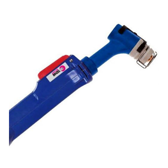
    5 Inbetriebnahme 5.2 Handschneidbrenner Der Brennerkopf ist im Winkel von 100° (PSB 31) bzw. 105° (PSB 60/121) zur Griffachse angeordnet. Die Verschleißteile Plasmadüse, Schutzkappe, Elektrode und Isolator sind durch Stecken oder Schrauben austauschbar. Zum Schutz des Bedieners ist der Brenner mit einer Sicherungsklemme ausgestattet, welche durch Lösen der Verschleißteile automatisch den Einschaltstromkreis unterbricht.
  • Seite 10 5 Inbetriebnahme VORSICHT Verletzungsgefahr Körperliche Schäden durch Beschädigung der Komponenten. • Verschmutzte Düsenbohrungen verringern den Luftdurchsatz und die Kühlung. Dadurch erhöht sich der Verschleiß aller Ausrüstteile bis zur Zerstörung des Brennerkörpers. Achten Sie immer auf festen Sitz und einen sauberen Zustand der Schutzkappe und aller Verschleißteile! 1 Elektrode einschrauben und mit Mehrfachschlüssel anziehen.
  • Seite 11 Elektrode 15mm - Plasmadüse schmal ø1,0 14 Feder 18 Federhülse Stand. 15,5mm Elektrodenschlüssel 15 Plasmadüse ø1,0 bzw. 19 Feder 10 Schutzkappe 20 Isolierhülse Elektrode lang ø1,2 11 Federring 16 Schutzkappe 21 Sicherungsklemme Allzweckschlüssel Isolierhülse Abb. 1 Brennerkörper PSB 31 DE - 11...
  • Seite 12 5 Inbetriebnahme PSB 60 PSB 121 Brennerkörper PSB 60 Plasmadüse für 30° Vorr. 12 Abstandsdüse 18 Plasmadüse ø1,0; Brennerkörper PSB 121 ø1,0; 1,3; 1,5; 1,8; 2,0 13 Abstandsdüsenträger 1,3; 1,5; 1,8; 2,0 Handgriff Federträger, Fasenschnitt 14 Abstandsdüse 19 Sicherungsklemme Elektrode Elektrodenschlüssel 15 Feder Allzweckschlüssel...
  • Seite 13: Plasma-Schneidbrenner Anschließen

    5 Inbetriebnahme AUT PSB 60 AUT PSB 121 Griffrohr AUT Plasmadüse ø1,0; 1,3; 1,5; 1,8; 2,0 Elektrodenschlüssel Elektrode Federträger Allzweckschlüssel Abb. 3 AUT PSB 60 und AUT PSB121 5.5 Plasma-Schneidbrenner anschließen HINWEIS • Achten Sie auf die richtige Zuordnung und den festen Sitz der Anschlüsse.
  • Seite 14: Pressluft Für Plasma- Und Kühlgas

    • Vorfilter 5µm Filterfeinheit • Submikrofilter 0,01µm Filterfeinheit • 99,99% Ölabscheiderate • Luftdurchsatz bei PSB 31 mind. 4,5bar: >160 l/min Luftdurchsatz bei PSB 60 mind. 6,0bar: >180 l/min Luftdurchsatz bei PSB121 mind. 6,0bar: >180 l/min  Tab. 4 auf Seite DE-6 5.6 Plasma-Schneidbrenner mit Zentralanschluss...
  • Seite 15: Bedienelemente

    • Beim betätigen des Tasters (am Handbrenner) und nach einer Gasvorströmzeit wird der Plasmapilotlichtbogen durch Hochfrequenzimpulse gezündet. Ausnahme: PSB 31 mit KZS oder KKS Ausrüstung • Beim Starten des Startlichtbogens (mit Softstarteinrichtung) darf die Schneiddüse das Werkstück nicht berühren. • Verwenden Sie die Zubehörelemente für einen optimalen Schneiddüsenabstand zum Werkstück.
  • Seite 16: Außerbetriebnahme

    3 Auf federnde Funktion und einwandfreien Sitz der Sicherungsklemme achten. Wenn nötig reinigen Sie die Kontaktflächen der Sicherungsklemme und Brennerkontaktstifte für eine sichere Kontaktierung, ggf. austauschen. Im Reparaturfall bietet ABICOR BINZEL Werksreparaturen an. 9 Störungen und deren Behebung GEFAHR Verletzungsgefahr und Geräteschäden durch unautorisierte Personen Unsachgemäße Reparaturen und Änderungen am Produkt können zu...
  • Seite 17 9 Störungen und deren Behebung Beachten Sie das beiliegende Dokument Gewährleistung. Wenden Sie sich bei jedem Zweifel und/oder Problemen an Ihren Fachhändler oder an den Hersteller. HINWEIS • Beachten Sie auch die Betriebsanleitungen der schweißtechnischen Komponenten wie z.B. Schweißbrenner, Robotersteuerung. Störung Ursache Behebung...
  • Seite 18: Demontage

    10 Demontage Störung Ursache Behebung Ausgebrannte • beschädigte oder lose Düse • Düse bzw. Schutzkappe handfest anziehen, ggf. Düse erneuern Schneiddüse • Werkstückkontakt • Kontaktierung vermeiden • zu schneller Schnittbeginn an • Schnittbeginn mit geringerer Werkstückkante Geschwindigkeit ausführen • Pilotlichtbogen zu lange und zu oft •...
  • Seite 19: Entsorgung

    Dieses Produkt besteht zum größten Teil aus Kunststoff, Stahl und Buntmetallen.  11 Entsorgung auf Seite DE-19 11.2 Verpackungen ABICOR BINZEL hat die Transportverpackung auf das Notwendigste reduziert. Bei der Auswahl der Verpackungsmaterialien wird auf eine mögliche Wiederverwertung geachtet. DE - 19...
  • Seite 20 All brand names and trademarks that appear in this manual are the property of their respective owners/manufacturers. Our latest product documents as well as all contact details for the ABICOR BINZEL national subsidiaries and partners worldwide can be found on our website at www.binzel-abicor.com...
  • Seite 21: Designated Use

    For operation, a cutting power source is required. The cutting torches may only be operated using original ABICOR BINZEL spare parts. 1.1 CE marking This device fulfils the requirements of the relevant EU directives.
  • Seite 22: Emergency Information

    3 Product description 2.2 Classification of the warnings The warnings used in the operating instructions are divided into four different levels and are shown prior to potentially dangerous work steps. Arranged in descending order of importance, they have the following meaning: DANGER Describes an imminent threatening danger.
  • Seite 23: Technical Data

    Ambient temperature for transport - 25 °C to + 55 °C Relative humidity up to 90 % at 20 °C Tab. 2 Ambient conditions for shipment and storage PSB 31 PSB 60 AUT PSB 60 PSB 121 AUT PSB 121 Application process...
  • Seite 24 Type Plasma max. current Steel Stainless Aluminium nozzle intensity steel ø PSB 31 max. 6 max. 8 max. 1,5 PSB 60 max. 10 max. 9 max. 3 AUT PSB 60 max. 15 max. 13 max. 5 PSB 121 max.
  • Seite 25: Nameplate

    4 Scope of delivery 3.2 Abbreviations Direct current Duty cycle Duty cycle Voltage rating Classification of the insulation resistance, voltage strength and protection type designates the series of manual torches AUT-PSB Automatic torches ...KZS Contact ignition ...KKS Short-circuit ignition ...HFS Non-contact ignition Tab.
  • Seite 26: Putting Into Operation

    All elements together form an operating unit which provides a plasma arc for cutting when supplied with the appropriate operating resources. When cutting, compressed air is ionized in the cutting nozzle. In PSB 31 KKS and KZS, this is done by means of short-circuit ignition. The initial arc produces a conductive plasma which is accelerated in the nozzle and directed to the part.
  • Seite 27: Accessories

    5 Putting into operation 5.2 Manual cutting torch The torch head is positioned at an angle of 100° (PSB 31) or 105° (PSB 60/111), relative to the handle axis. The wear parts plasma nozzle, protective cap, electrode and insulator are parts that can be replaced simply by inserting them or screwing them in.
  • Seite 28: Risk Of Injury

    5 Putting into operation 5.4 Equipping the torch body WARNING Risk of injury Dangerous voltage due to plasma power source. • All manual plasma-cutting torches are equipped with a torch-specific fuse terminal for protection of the operator. To disconnect the wear parts, it must be removed, automatically interrupting the switch-on circuit.
  • Seite 29 15.5mm 10 Protection cap 15 Plasma nozzle 19 Spring 11 Spring ring 20 Insulating sleeve Electrode, long ø1.0 or ø1.2 16 Protection cap 21 Fuse terminal General purpose wrench Insulating sleeve Fig. 1 Torch body PSB 31 EN - 11...
  • Seite 30 5 Putting into operation PSB 60 PSB 121 Torch body PSB 60 Plasma nozzle for 30° 12 Spacer nozzle 18 Plasma nozzle ø1.0; Torch body PSB 121 device ø1.0; 1.3; 1.5; 13 Spacer nozzle holder 1.3; 1.5; 1.8; 2.0 Handle 1.8;...
  • Seite 31 5 Putting into operation AUT PSB 60 AUT PSB 121 Handle tube AUT Plasma nozzle ø1.0; 1.3; 1.5; 1.8; 2.0 Electrode wrench Electrode Spring receiver General purpose wrench Fig. 3 AUT PSB 60 and AUT PSB121 5.5 Connecting the plasma-cutting torch NOTICE •...
  • Seite 32 • Submicro filter 0.01 µm of retained particle size • 99.99% of oil separation rate • Air throughput for PSB 31 at least 4.5bar: >160 l/min Air throughput for PSB 60 at least 6.0bar: >180 l/min Air throughput for PSB 121 at least 6.0bar: >180 l/min ...
  • Seite 33: Operating Elements

    • The plasma pilot arc is struck by a high frequency pulse when the trigger (on the manual torch) is actuated and after a gas pre-flow time. Exception: PSB 31 equipped with KZS or KKS • Upon starting the pilot arc (via the soft start device), the cutting nozzle must not touch the work-piece.
  • Seite 34: Putting Out Of Operation

    3 Ensure elastic function and proper fit of the fuse terminal. If required, clean the contact faces of the fuse terminal and the torch contact pins to ensure a reliable contact, and replace them, if necessary. ABICOR BINZEL offers repair services at the factory. 9 Troubleshooting DANGER...
  • Seite 35 9 Troubleshooting NOTICE • Please also consult the operating instructions for the welding components, such as welding torch, robot control. Fault Cause Solution Insufficient penetration • Pressure drop during cutting • Reset pressure monitor • Cutting rate too high • Reduce cutting rate •...
  • Seite 36 This product consists for the most part of plastics, steel and non-ferrous metals.  11 Disposal on page EN-18 11.2 Packaging ABICOR BINZEL has reduced the packaging for shipping to a minimum. Packaging materials are always selected with regard to their possible recycling ability.
  • Seite 37 11 Disposal EN - 19...
  • Seite 38 Toutes les marques déposées et marques commerciales contenues dans le présent mode d'emploi sont la propriété de leurs titulaires/fabricants respectifs. Vous trouverez nos documents actuels sur les produits, ainsi que l’ensemble des coordonnées des représentants et des partenaires d'ABICOR BINZEL dans le monde sur la page d'accueil www.binzel-abicor.com Identification FR-3 Eléments de commande...
  • Seite 39: Utilisation Conforme Aux Dispositions

    Une source de courant de coupage est nécessaire au fonctionnement. Les torches de coudage ne doivent être exploitées qu'avec des pièces de rechange d’origine ABICOR BINZEL. 1.1 Marquage CE Cet appareil est conforme aux exigences relatives aux directives européennes en vigueur.
  • Seite 40: Classification Des Consignes D'avertissement

    2 Sécurité 2.2 Classification des consignes d’avertissement Les consignes d'avertissement utilisées dans le mode d'emploi sont divisées en quatre niveaux différents. Elles sont indiquées avant les étapes de travail potentiellement dangereuses. Elles sont classées par ordre d'importance décroissant et ont la signification suivante : DANGER Signale un danger imminent.
  • Seite 41: Description Du Produit

    Transport, température de l'air ambiant - 25 °C bis + 55 °C Humidité de l'air relative bis 90 % bei 20 °C Tab. 2 Conditions environnementales de transport et de stockage PSB 31 PSB 60 AUT PSB 60 PSB 121 AUT PSB 121 Application...
  • Seite 42 à la pièce, les caractéristiques du poste, la vitesse de coupe. Type Tuyère Puissance max. Acier Acier Aluminium plasma inoxydable ø PSB 31 max. 6 max. 8 max. 1,5 PSB 60 max. 10 max. 9 max. 3 AUT PSB 60 max. 15 max. 13 max.
  • Seite 43: Plaque Signalétique

    3 Description du produit Longueur standard 6 m (autres longueurs possibles) Raccord courant/air comprimé G1/4 Type de raccord Raccord vissé ou centralisé Tab. 6 Faisceau 3.2 Abréviations Courant continu F.d.m Facteur de marche Gamme de tension Isolation, tension admissible et classe de protection Désigne la gamme de torches manuelles AUT-PSB Torches automatiques...
  • Seite 44: Signes Et Symboles Utilisés

    L’ensemble complété par l’alimentation en air et en courant crée un arc plasmagène permettant le coupage. Lors du coupage, l’air comprimé est ionisé dans la tuyère par un courant haute fréquence. Pour PSB 31 KKS et KZS, cela s'effectue au moyen d'un allumage par court-circuit. L’arc pilote crée un plasma conducteur qui est accéléré...
  • Seite 45 (en Allemagne, voir TRBS 1203). 5.2 Torche de coupage manuelle La tête de torche est disposée dans un angle de 100° (PSB 31) ou 105° (PSB 60/121) par rapport à l'axe de la poignée. Les pièces d'usure, buse plasma, coiffe de protection, électrode et isolant peuvent être remplacées en les insérant ou vissant.
  • Seite 46: Risque De Blessure

    5 Mise en service 5.4 Equiper le corps de torche AVERTISSEMENT Risque de blessure Tension dangereuse provenant de la source de courant plasma. • Toutes les torches de coupage manuelles plasma sont équipées d'une borne-fusible spécifique à la torche et garantissant la protection de l'utilisateur.
  • Seite 47 15 Tuyère plasma ø1,0 ou 19 Ressort Electrode longue Clé d'électrode ø1,2 20 Douille isolante Clé universelle 10 Coiffe de protection 16 Coiffe de protection 21 Borne-fusible Douille isolante 11 Rondelle élastique Fig. 1 Corps de torche PSB 31 FR - 11...
  • Seite 48 5 Mise en service PSB 60 PSB 121 Corps de torche PSB 60 Tuyère plasma pour 30° 12 Buse d'écartement 18 Tuyère plasma ø1,0; Corps de torche PSB priorité ø1,0; 1,3; 1,5; 13 Support de buse 1,3; 1,5; 1,8; 2,0 1,8;...
  • Seite 49 5 Mise en service AUT PSB 60 AUT PSB 121 Tube de poignée AUT Tuyère plasma ø1,0; 1,3; 1,5; 1,8; 2,0 Clé d'électrode Electrode Support de ressort Clé universelle Fig. 3 AUT PSB 60 et AUT PSB121 5.5 Raccorder les torches de coupage plasma AVIS •...
  • Seite 50 • Microfiltre avec une finesse de filtre de 0,01µm • Capacité de séparation de l'huile de 99,99% • Débit d'air minimal pour PSB 31 4,5 bars : >160 l/min Débit d'air minimal pour PSB 60 6,0 bars : >180 l/min Débit d'air minimal pour PSB 121 6,0 bars : >180 l/min...
  • Seite 51: Eléments De Commande

    6 Eléments de commande 5.7 Processus de coupage ATTENTION Risque de blessure • Avant toute opération de coupage, contrôler votre équipement de protection personnel. AVIS • Tous les paramètres nécessaires (comme par exemple courant de coupage, softstart, air comprimé etc.) doivent être réglés conformément à...
  • Seite 52: Mise Hors Service

    Exception : PSB 31 avec équipement KZS ou KKS • Veillez à ce que la tuyère ne soit pas en contact avec la pièce lors de l'amorçage de l'arc pilote (avec équipement softstart).
  • Seite 53 3 Veiller au fonctionnement élastique et au serrage correct de la borne-fusible Si nécessaire, nettoyez les surfaces de contact de la borne-fusible et remplacer les fiches de contact de la torche afin d'obtenir un contact sûr. Les réparations peuvent être effectuées par ABICOR BINZEL. 9 Dépannage DANGER Risque de blessures et d'endommagement de l'appareil en cas d'utilisation par des personnes non autorisées...
  • Seite 54 9 Dépannage Défaut Déterminer Solution Pénétration insuffisante • Perte de pression durant la • Régler à nouveau le manostat coupage • Vitesse de coupe trop élevée • Réduire la vitesse de coupe • Angle d’inclinaison de la torche • Réduire l'angle d'inclinaison trop important •...
  • Seite 55 10 Démontage Défaut Déterminer Solution Electrode détruite par le • Perte de pression en cours de • Corriger le réglage du manostat coupe liée à un mauvais réglage du manostat • Electrode mal montée • Visser l'électrode à la main •...
  • Seite 56 Ce produit est composé en majeure partie de matières plastiques, d'acier et de métaux non ferreux.  11 Elimination Page FR-20 11.2 Emballages ABICOR BINZEL a réduit l'emballage de transport au nécessaire. Lors du choix des matériaux d'emballage, veiller à ce que ces derniers soient recyclables. FR - 20...
  • Seite 57 11 Elimination FR - 21...
  • Seite 58 Para obtener la documentación actual sobre nuestros productos así como para conocer los datos de contacto de los representantes locales y socios de ABICOR BINZEL en todo el mundo, consulte nuestra página de inicio en www.binzel-abicor.com Identificación...
  • Seite 59: Seguridad

    Para el funcionamiento se necesita una fuente de corriente de corte. Las antorchas de corte deben utilizarse solamente con piezas de recambio originales de ABICOR BINZEL. 1.1 Marca CE Este aparato satisface los requisitos de las directivas de la UE vigentes.
  • Seite 60 2 Seguridad 2.2 Clasificación de las advertencias Las advertencias empleadas en este Instructivo de servicio se dividen en cuatro niveles diferentes y se indican antes de operaciones potencialmente peligrosas. Ordenadas de mayor a menor importancia, significan lo siguiente: ¡PELIGRO! Indica un peligro inminente. Si no se evita, las consecuencias son la muerte o lesiones muy graves.
  • Seite 61: Descripción Del Producto

    - 25 °C bis + 55 °C Humedad relativa del aire bis 90 % bei 20 °C Tab. 2 Condiciones ambientales para transporte y almacenamiento PSB 31 PSB 60 AUT PSB 60 PSB 121 AUT PSB 121 Proceso de aplicación...
  • Seite 62 Tipo Tobera Intensidad de Acero Acero Aluminio plasma corriente máx. inoxidabl ø PSB 31 máx. 6 máx. 8 máx. 1,5 PSB 60 máx. 10 máx. 9 máx. 3 AUT PSB 60 máx. 15 máx. 13 máx.
  • Seite 63: Placa De Identificación

    3 Descripción del producto Longitud estándar 6 m (otras longitudes disponibles bajo pedido) Conexión cable eléctrico/aéreo G1/4 Modelo Conector individual o central Tab. 6 Conjunto de cables 3.2 Abreviaciones Corriente continua C.T. Ciclo de trabajo Medición de tensión Clasificación de resistencia de aislamiento, rigidez dieléctrica y modo de protección Denominación de la serie de antorchas manuales AUT-PSB...
  • Seite 64: Puesta En Servicio

    Al cortar se ioniza el aire comprimido en la tobera de corte por medio de alta frecuencia de impulsos. En las antorchas PSB 31 KKS y KZS se realiza mediante el encendido por cortocircuito. El arco de arranque genera plasma conductivo, el cual se acelera en la tobera y es conducido a la pieza de trabajo.
  • Seite 65 (en Alemania, véase TRBS 1203). 5.2 Antorcha de corte manual El cabezal de antorcha está posicionado en un ángulo de 100° (PSB 31) o 105° (PSB 60/121) hacia el eje de la empuñadura. Las piezas de repuesto tobera plasma, protector, electrodo y aislante son cambiables, van atornillados o deslizados.
  • Seite 66: Riesgo De Lesiones

    5 Puesta en servicio 5.4 Equipar el cuerpo de antorcha ¡ADVERTENCIA! Riesgo de lesiones Tensión peligrosa debido a la fuente de corriente de plasma • Todas las antorchas de corte manual por plasma están dotadas de un borne de fusible específico de la antorcha para proteger el operador. Para desconectar las piezas de repuesto hay que sacar el borne de fusible y el circuito de encendido se interrumpe automáticamente.
  • Seite 67 15 Tobera gas diám. 1,0 19 Muelle 20 Casquillo aislante Electrodo, largo Llave para el electrodo ó 1,2 Terminal fusible 10 Protector 16 Protector Llave universal Casquillo aislante 11 Arandela del muelle Fig. 1 Cuerpo de antorcha PSB 31 ES - 11...
  • Seite 68 5 Puesta en servicio PSB 60 PSB 121 Cuerpo de antorcha Tobera plasma para disp. 12 Tobera distanciadora 18 Tobera plasma PSB 60 30° diám. 1,0; 1,3; 1,5; 13 Portador de tobera diám. 1,0; 1,3; 1,5; Cuerpo de antorcha 1,8; 2,0 distanciadora 1,8;...
  • Seite 69 5 Puesta en servicio AUT PSB 60 AUT PSB 121 Tubo cilíndrico AUT Tobera plasma diám. 1,0; 1,3; 1,5; 1,8; 2,0 Llave para el electrodo Electrodo Muelle receptor Llave universal Fig. 3 AUT PSB 60 y AUT PSB121 ES - 13...
  • Seite 70 5 Puesta en servicio 5.5 Conectar la antorcha de corte por plasma AVISO • Asegurarse de que las conexiones estén asignadas correctamente y bien sujetas. • Como la tobera plasma no está protegida contra el contacto directo por motivos técnicos, la fuente de corriente para el corte por plasma no cumple los requisitos de la norma EN 60974-7, punto 7.4.2.
  • Seite 71 • Submicrofiltro con finura de filtro de 0,01 µm • Capacidad separadora de aceite de un 99,99 % • Paso de aire de PSB 31 mín. 4,5 bares: >160 l/min Paso de aire de PSB 60 mín. 6,0 bares: >180 l/min Paso de aire de PSB 121 mín.
  • Seite 72: Elementos De Mando

    Excepción: PSB 31 equipado con KZS o KKS • Al iniciar el arco de arranque (con dispositivo de arranque suave), la boquilla de corte no debe estar tocando la pieza de trabajo.
  • Seite 73: Puesta Fuera De Servicio

    3 Controlar si el borne de fusible es flexible y está fijado correctamente. Limpiar las superficies de contacto del borne de fusible y reemplazar los contactos de la antorcha si fuera necesario. En caso de reparaciones ABICOR BINZEL ofrece reparaciones en fábrica. 9 Averías y su eliminación ¡PELIGRO! Riesgo de lesiones y daños en el aparato por personas no...
  • Seite 74 9 Averías y su eliminación También debe observarse el documento adjunto con las condiciones de la garantía. En caso de dudas y/o problemas, diríjase a su proveedor especializado o al fabricante. AVISO • Observar también el manual de instrucciones de los componentes de soldadura, por ejemplo, antorcha de soldadura, control del robot.
  • Seite 75 10 Desmontaje Avería Causa Eliminación Boquilla de corte • Tobera defectuosa o suelta • Apretar a mano la tobera y el protector, cambiar la tobera si quemada fuera necesario • Contacto con la pieza de trabajo • Evitar el contacto •...
  • Seite 76 Este producto es en gran parte de plástico, acero y metales no férreos.  11 Eliminación en página ES-20 11.2 Embalajes ABICOR BINZEL ha reducido el embalaje de transporte a un mínimo necesario. Al seleccionar los materiales de embalaje, se tiene en cuenta un posible reciclaje.
  • Seite 77 11 Eliminación Notas ES - 21...
  • Seite 78 11 Eliminación Notas ES - 22...
  • Seite 79 11 Eliminación ES - 23...
  • Seite 80 T E C H N O L O G Y F O R T H E W E L D E R ´ S W O R L D Alexander Binzel Schweisstechnik GmbH & Co.KG Postfach 10 01 53 • D–35331 Giessen Tel.: ++49 (0) 64 08 / 59–0 Fax:...

Diese Anleitung auch für:

Psb 60Psb 121Aut psb 121Aut psb 60

Inhaltsverzeichnis