Abicor Binzel iROB Pulse 400 Betriebsanleitung
Inhaltsverzeichnis
Verfügbare Sprachen
Verfügbare Sprachen
T E C H N O L O G Y F O R T H E W E L D E R ´ S W O R L D .
DE Betriebsanleitung / EN Operating instructions
FR Mode d´emploi / ES Instructivo de servicio
IT Istruzioni per l'uso
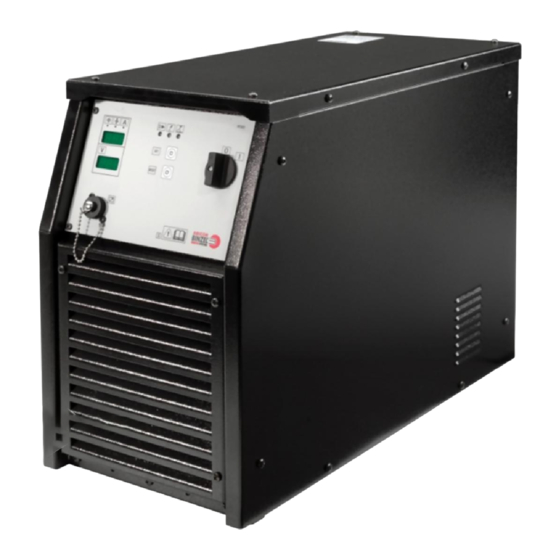
iROB Pulse 400/400 MV/500
DE Roboterschweißstromquelle
EN Robot Welding Power Source
FR Source de courant pour soudage robotisé
ES Equipo de soldadura robótica
IT Generatore per saldatura robotizzato
DIN EN
ISO 9001
www.binzel-abicor.com
Kapitel
Inhaltsverzeichnis
Fehlerbehebung

Verwandte Anleitungen für Abicor Binzel iROB Pulse 400


Inhaltszusammenfassung für Abicor Binzel iROB Pulse 400
- Seite 1 T E C H N O L O G Y F O R T H E W E L D E R ´ S W O R L D . DE Betriebsanleitung / EN Operating instructions FR Mode d´emploi / ES Instructivo de servicio IT Istruzioni per l‘uso iROB Pulse 400/400 MV/500 DE Roboterschweißstromquelle EN Robot Welding Power Source FR Source de courant pour soudage robotisé...
-
Seite 2: Inhaltsverzeichnis
Produktes erforderlich werden. Diese Änderungen werden jedoch in neuen Ausgaben berücksichtigt. Alle in der Betriebsanleitung genannten Handelsmarken und Schutzmarken sind Eigentum der jeweiligen Besitzer/Hersteller. Unsere aktuellen Produktdokumente, sowie alle Kontaktdaten der ABICOR BINZEL Ländervertretungen und Partner weltweit, finden Sie auf unserer Homepage www.binzel-abicor.com... -
Seite 3: Identifikation
Anforderungen für den Automaten- bzw. Roboterbetrieb. Folgende Ausführungen sind verfügbar: • iROB Pulse 400, iROB Pulse 400 MV, iROB Pulse 500 Der modulare Aufbau gestattet eine individuelle mechanische und elektronische Anpassung über analoge Ein-/Ausgänge oder digitale BUS-Systeme. Die Roboterschweißstromquelle iROB Pulse darf nur mit Original ABICOR BINZEL Ersatzteilen betrieben werden. -
Seite 4: Persönliche Schutzausrüstung (Psa) De
Systemimpedanz ZMAX an der Schnittstelle zwischen Zuleitung des Nutzers und dem öffentlichen System kleiner oder gleich zu 0,038 Ohm für iROB Pulse 500 und 0,06 Ohm für iROB Pulse 400 ist. Es liegt in der Verantwortung des Installateurs oder des Betreibers sicherzustellen, falls notwendig auch durch Rücksprache mit dem Verteilungsnetzbetreiber, dass das Gerät nur an einen Anschluss mit... -
Seite 5: Warn- Und Hinweisschilder De
iROB Pulse 2 Sicherheit • Setzen Sie das Elektrogerät nie dem Regen aus und vermeiden Sie eine feuchte oder nasse Umgebung. • Schützen Sie sich vor Stromunfällen, indem Sie isolierende Unterlagen verwenden und trockene Kleidung tragen. • Verwenden Sie das Elektrogerät niemals in Bereichen, wo Brand- oder Explosionsgefahr besteht. •... -
Seite 6: Produktbeschreibung
3 Produktbeschreibung iROB Pulse 3 Produktbeschreibung 3.1 Technische Daten Abb. 1 Abmessungen Roboterschweißstromquelle iROB Pulse iROB Pulse 400 iROB Pulse 400 MV iROB Pulse 500 Netzspannung 3x400 Vac 3x400 Vac 3x400 Vac 3x320 Vac ± Netzspannnungstoleranz 15 % Netzfrequenz 50/60 Hz... -
Seite 7: Abkürzungen Und Maßangaben De
Pulse 3 Produktbeschreibung iROB Pulse 400 iROB Pulse 400 MV iROB Pulse 500 X=100 % 340 A 400 A Schweißstrom bei 25° C X=50 % 400 A 500 A X=60 % 400 A 500 A X=100 % 400 A 470 A Schweißstrombereich... -
Seite 8: Produktbeschreibung
Antriebseinheit (Master) Baugröße 1 = Rollen-ø 20 mm MF1 MasterPull WHPPI Bezeichnet den Wechselkörper in Push-Pull-Ausführung Tab. 6 Das iROB-System 3.4 Typenschild Die Roboterschweißstromquelle ist am Gehäuse mit einem Typenschild wie folgt gekennzeichnet: Abb. 2 Typenschild iROB Pulse 400 DE - 8 BAL.0323.0 • 2017-08-31... - Seite 9 Pulse 3 Produktbeschreibung Abb. 3 Typenschild iROB Pulse 400 MV Abb. 4 Typenschild iROB Pulse 500 Beachten Sie für alle Rückfragen folgende Angaben: • Gerätetyp, Gerätenummer BAL.0323.0 • 2017-08-31 DE - 9...
-
Seite 10: Verwendete Zeichen Und Symbole De
3 Produktbeschreibung iROB Pulse 3.5 Verwendete Zeichen und Symbole In der Betriebsanleitung werden folgende Zeichen und Symbole verwendet: Symbol Beschreibung • Aufzählungssymbol für Handlungsanweisungen und Aufzählungen Querverweissymbol verweist auf detaillierte, ergänzende oder weiterführende Informationen Handlungsschritt/e im Text, die der Reihenfolge nach durchzuführen sind DE - 10 BAL.0323.0 •... -
Seite 11: Lieferumfang
iROB Pulse 4 Lieferumfang 4 Lieferumfang • Roboterschweißstromquelle iROB Pulse • Betriebsanleitung • Stromkabel (offen) Roboterschweißstromquelle iROB Pulse - Stromnetz Tab. 7 Lieferumfang • Kühlgerät iROB Cool • Fernregler iROB Control (nur für flüssiggekühlte Ausführung) • Montageplattform • Stecker für Stromkabel (offen) Roboterschweißstromquelle iROB Pulse - Stromnetz Tab. -
Seite 12: Funktionsbeschreibung
5 Funktionsbeschreibung iROB Pulse 5 Funktionsbeschreibung iFEED MP iFEED Comfort iROB iCOOL ® ® iROB Spool Brennerhals ABIROB 11 Fernregler iROB Control 15 Brennerhals ABIROB Korbspulenhalter ® Masterantrieb MF1 Masterliner 12 Umlaufkühlgerät iROB Cool 16 Brennerhals ABIROB ® Roboter Fassspule 13 Roboterschweißstromquelle 17 Brennerhals ABIROB iROB Feed... -
Seite 13: Inbetriebnahme
iROB Pulse 6 Inbetriebnahme 6 Inbetriebnahme GEFAHR Verletzungsgefahr durch unerwarteten Anlauf Für die gesamte Dauer von Wartungs-, Instandhaltungs-, Montage- bzw. Demontage- und Reparaturarbeiten ist Folgendes zu beachten: • Schalten Sie die Stromquelle aus. • Sperren Sie die Gaszufuhr ab. • Sperren Sie die Druckluftzufuhr ab. •... -
Seite 14: Transportieren Und Aufstellen De
6 Inbetriebnahme iROB Pulse 6.1 Transportieren und Aufstellen VORSICHT Verletzungsgefahr Körperliche Schäden durch herunterfallende Geräte und Anbauteile. • Verwenden Sie zum Transportieren und Aufstellen der Roboterschweißstromquelle iROB Pulse ein geeignetes Hebezeug mit Lastaufnahmemitteln. • Vermeiden Sie ruckartiges Anheben und Absetzen. •... -
Seite 15: Roboterschweißstromquelle Irob Pulse Anschließen
iROB Pulse 6 Inbetriebnahme 6.4 Roboterschweißstromquelle iROB Pulse anschließen HINWEIS • Beachten Sie die Betriebsanleitungen der schweißtechnischen Komponenten Umlaufkühlgerät iROB Cool (optional), Drahtvorschubgerät iROB Feed (optional), Fernregler iROB Control (optional) und Schweißbrenner. Gasanschluss Anschlussbuchse Schweißstrom negativ Anschluss Kühlmittelrücklauf 10 Kühlmittelrücklaufschlauch CAN-Bus Anschlussbuchse Schweißstrom positiv Massekabel... -
Seite 16: Netzanschluss
6 Inbetriebnahme iROB Pulse 6.4.2 Netzanschluss GEFAHR Stromschlag Gefährliche Spannung durch fehlerhafte Kabel. • Überprüfen Sie alle spannungsführenden Kabel und Verbindungen auf ordnungsgemäße Installation und Beschädigungen. • Tauschen Sie schadhafte, deformierte oder verschlissene Teile aus. GEFAHR Personen- und Sachschäden Unsachgemäßer Netzanschluss kann zu Personen- und Sachschäden führen. •... -
Seite 17: Betrieb
iROB Pulse 7 Betrieb 7 Betrieb HINWEIS • Die Bedienung des Gerätes ist ausschließlich befähigten Personen (in Deutschland siehe TRBS 1203) vorbehalten. • Beachten Sie die Betriebsanleitungen der schweißtechnischen Komponenten Umlaufkühlgerät iROB Cool (optional), Drahtvorschubgerät iROB Feed (optional), Fernregler iROB Control (optional) und Schweißbrenner. - Seite 18 7 Betrieb iROB Pulse Symbol Pos. Bezeichnung Ermöglicht die Anzeige von Drahtvorschubgeschwindigkeit, empfohlene Materialstärke, Schweißstrom und Fehlercodes. Leuchtet, wenn das Roboterschweißsystem an die Stromversorgung angeschlossen und eingeschaltet ist. Es erfolgt eine Anzeige der Error-Meldung an den digitalen Anzeigen. 10 Störungen und deren Behebung auf Seite DE-21 Leuchtet, wenn an den Ausgangsklemmen der Anlage Spannung anliegt.
-
Seite 19: Außerbetriebnahme
iROB Pulse 8 Außerbetriebnahme Blindabdeckung Anschlussbuchse CAN-Bus Anschlussbuchse Schweißstrom positiv Roboterinterface RI 1000/2000/3000 Durchführung Anschlusskabel Anschlussbuchse Schweißstrom negativ Blindabdeckung Anschlussbuchse Anschlussbuchse Steuerleitung Brennerreinigungsstation Zwischenschlauchpaket Abb. 8 Rückansicht Symbol Pos. Bezeichnung Anschluss (CAN-BUS) Anschluss Steuerleitung Zwischenschlauchpaket Anschluss Schweißstrom positiv Anschluss Schweißstrom negativ (Massekabel) 8 Außerbetriebnahme HINWEIS •... -
Seite 20: Wartung Und Reinigung
9 Wartung und Reinigung iROB Pulse 9 Wartung und Reinigung Die Roboterschweißstromquelle iROB Pulse ist bei normalen Betriebsbedingungen wartungsfrei. Regelmäßige und dauerhafte Wartung und Reinigung sind jedoch Voraussetzung für eine lange Lebensdauer und eine einwandfreie Funktion. GEFAHR Verletzungsgefahr durch unerwarteten Anlauf Für die gesamte Dauer von Wartungs-, Instandhaltungs-, Montage- bzw. -
Seite 21: Störungen Und Deren Behebung
iROB Pulse 10 Störungen und deren Behebung 10 Störungen und deren Behebung GEFAHR Verletzungsgefahr und Geräteschäden durch unautorisierte Personen Unsachgemäße Reparaturen und Änderungen am Produkt können zu erheblichen Verletzungen und Geräteschäden führen. Die Produktgarantie erlischt bei Eingriff durch unautorisierte Personen. •... -
Seite 22: Demontage
11 Demontage iROB Pulse 11 Demontage GEFAHR Verletzungsgefahr durch unerwarteten Anlauf Für die gesamte Dauer von Wartungs-, Instandhaltungs-, Montage- bzw. Demontage- und Reparaturarbeiten ist Folgendes zu beachten: • Schalten Sie die Stromquelle aus. • Sperren Sie die Gaszufuhr ab. • Sperren Sie die Druckluftzufuhr ab. •... -
Seite 23: Entsorgung
Betriebsmittelhersteller vorgegebenen Sicherheitsdatenblätter. Kontaminierte Reinigungswerkzeuge (Pinsel, Lappen usw.) müssen ebenfalls entsprechend den Angaben des Betriebsmittelherstellers entsorgt werden. 12.3 Verpackungen ABICOR BINZEL hat die Transportverpackung auf das Notwendigste reduziert. Bei der Auswahl der Verpackungsmaterialien wird auf eine mögliche Wiederverwertung geachtet. BAL.0323.0 • 2017-08-31... -
Seite 24: Anhang
13 Anhang iROB Pulse 13 Anhang 13.1 Ersatzteile 33 32 Abb. 9 Ersatzteile iiROB Pulse 400/iROB Pulse 400 MV/iROB Pulse 500 Pos. Artikelbezeichnung iROB Pulse 400 iROB Pulse 400 MV iROB Pulse 500 Kabelbaum Temperatursensor Hutschiene Platine Abdeckblech, oben Lüfter 60x60x15 (Buskarten) Tab. - Seite 25 Frontblech Lüfter 120x120x38 (Hauptlüfter) Diode (4Stk) Platine PFC Platine PFC Platine PFC iROB Pulse 400 iROB Pulse 400 MV/iROB Pulse 500 iROB Pulse 400 MV/iROB Pulse 500 Temperatursensor Seitenblech rechts Seitenblech rechts Seitenblech rechts iROB Pulse 400 iROB Pulse 400 MV...
-
Seite 26: Wartungsplan
13 Anhang iROB Pulse 13.2 Wartungsplan Wartungsplan Wartungs- durchzuführende ausgeführt Unterschrift/ nächste intervall Wartungsarbeiten Bemerkung Wartung Täglich Kabel und Verbindungsschläuche prüfen. Täglich Allgemeinen Zustand prüfen. Täglich Kühlluftzirkulation prüfen. Monatlich Bewegliche Teile und Lager auf Funktion prüfen. Vierteljährlich Lüfter auf Funktion prüfen, ggf. reinigen. -
Seite 27: Optionen
iROB Pulse 14 Optionen 14 Optionen 14.1 Roboterinterface Es stehen die Roboterinterfaces RI 1000, RI 2000 und RI 3000 zur Verfügung, die alle gängigen Robotermodelle unterstützen. 14.1.1 iROB RI 1000 und iROB RI 2000 Die Roboterinterfaces RI 1000 und RI 2000 sind Interfaces mit einer begrenzten Anzahl analoger und digitaler Ein- und Ausgänge. - Seite 132 T E C H N O L O G Y F O R T H E W E L D E R ´ S W O R L D . Alexander Binzel Schweisstechnik GmbH & Co.KG Postfach 10 01 53 • D–35331 Giessen Tel.: ++49 (0) 64 08 / 59–0 Fax:...