Herunterladen Inhalt Inhalt Diese Seite drucken
bürkert 2033 Bedienungsanleitung

bürkert 2033 Bedienungsanleitung

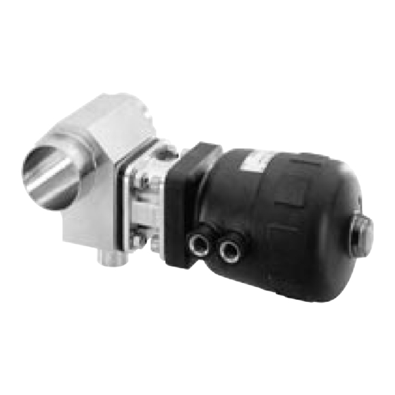
Kolbengesteuerte membranventile
Vorschau ausblenden Andere Handbücher für 2033:
Inhaltsverzeichnis

Werbung

Verfügbare Sprachen

Verfügbare Sprachen

2031-2032-2033
PISTON-OPERATED DIAPHRAGM VALVES
Instruction Manual
439692 - Nov05_F

Werbung

Inhaltsverzeichnis
loading

Inhaltszusammenfassung für bürkert 2033

  • Seite 1 2031-2032-2033 PISTON-OPERATED DIAPHRAGM VALVES Instruction Manual 439692 - Nov05_F...
  • Seite 2: Inhaltsverzeichnis

    During installation............................. 4 2.1.3 Installation for self-draining of the valve 2031 ................ 4 2.1.4 Installation of a tank outlet valve 2033 ..................5 SPECIFICATIONS............................6 3.1 GENERAL SPECIFICATIONS ......................6 3.2 ACTUATOR SPECIFICATIONS ..................... 6 3.3 DIAPHRAGM SPECIFICATIONS ....................7 3.4 VALVE BODY SPECIFICATIONS ....................
  • Seite 3: Introduction

    1.2 DESCRIPTION OF THE DIAPHRAGM VALVE The diaphragm valve 2031, 2032 or 2033 has been designed to control the flow of fluids, even charged or aggressive. This 2/2-way valve is made up of :...
  • Seite 4: Installation

    - Install the pipes with a 3 to 5% minimum gradient in the direction of flow. During the assembling of the valve in self draining position, the leakage detection hole must be at the lowest point. Self-draining in a process system is ultimately the responsibility of the system designer and/or end user. 2031-2032-2033...
  • Seite 5: Installation Of A Tank Outlet Valve 2033

    INSTALLATION 2.1.4 Installation of a tank outlet valve 2033 Refer to ASME VIII Division I «Boiler and pressure Vessel code» standard for further infor- mation on tanks and welding recommendations. We recommend to weld the tank outlet valve before mounting the tank. Nevertheless, welding valves on mounted tanks remains possible if need be.
  • Seite 6: Specifications

    Pressure [bar] (Function A) : ≥ 100 = 125 > 125 Do not use a control pressure higher than indicated to ensure the diaphragm lon- gevity. For more information on the reduced-strength actuators, please contact your nearest Bürkert agent. 2031-2032-2033...
  • Seite 7: Diaphragm Specifications

    Control pressure (bar) Control pressure (bar) Elastomer diaphragm 3.3 DIAPHRAGM SPECIFICATIONS - Material: • PTFE/EPDM • elastomer (EPDM, FPM or CSM) - Temperature of the medium Material Temperature [°C] PTFE ./ EPDM -10 to +130 EPDM -5 to +150 2031-2032-2033...
  • Seite 8: Valve Body Specifications

    Dynamic pressure: the valve being open, the pressure is applied in the whole valve body; the valve must close itself and be tight. Type of pressure Static Dynamic Material of the diaphragm Elastomer PTFE / EPDM Elastomer PTFE / EPDM Actuator size 2031-2032-2033...
  • Seite 9: Maintenance

    40, 50 012127 012125 40, 50 011494 011464 K, L Please contact your Burkert agent 4.1.2 Storing If the valve is stored for a long time, unscrew the body screws to avoid permanent change in shape of the diaphragm. 2031-2032-2033...
  • Seite 10: Dismantling The Diaphragm Valve 2031

    Before dismantling or opening the valve, turn-off the medium and control medium and depressurize the pipes. Dismantling security : the cover can be unscrewed without any risk (the spring loses its tension progressively). Gasket set Orifices (female thread G1/4“) Actuator Diaphragm 4 fixing screws Valve body 2031-2032-2033...
  • Seite 11: Spring-To-Close (A) Or Double-Acting (I) Valves

    - Apply again the control pressure indicated on the label to the lower orifice of the valve. - Check the torque rating of the 4 screws. Tighten if necessary. For 3A approved products, please use only sterile food grade lubricant complying with CFR 21 Part 178.3570. 2031-2032-2033...
  • Seite 12: Spring-To-Open (B) Valve

    (in Nm) specified below: Material of the diaphragm Elastomer PTFE/EPDM - Apply again the control pressure indicated on the label to the upper orifice of the valve. - Check the torque rating of the 4 screws. Tighten if necessary. 2031-2032-2033...
  • Seite 13: Dismantling The Diaphragm Valve 2032 Or 2033

    MAINTENANCE 4.3 DISMANTLING THE DIAPHRAGM VALVE 2032 OR 2033 Before dismantling or opening the valve, turn-off the medium and control medium and depressurize the pipes. Dismantling security : the cover can be unscrewed without any risk (the spring loses its tension progressively).
  • Seite 14 - Apply again the control pressure indicated on the label to the lower orifice of the valve. - Check the torque rating of the 4 nuts. Tighten if necessary. For 3A approved products, please use only sterile food grade lubricant complying with CFR 21 Part 178.3570. 2031-2032-2033...
  • Seite 15: Annex

    24 V= Jumper Valve 2031 and Pt100 Top Control 8630 5.2 CONTINUOUS PRESSURE CONTROL Between the Top Control 8630 mounted on a valve 2031 and the pressure transmitter 8323. 24 V= Jumper 8323 Valve 2031 and Top Con- trol 8630 2031-2032-2033...
  • Seite 16 ANNEX 2031-2032-2033...
  • Seite 17 2031-2032-2033 VANNES A MEMBRANE COMMANDEES PAR PISTON Manuel utilisateur...
  • Seite 18 Vanne utilisée en fonction A (NF) ou I (double-effet)............11 4.2.2 Vanne utilisée en fonction B (NO)....................12 4.3 DÉMONTAGE DE LA VANNE À MEMBRANE 2032 OU 2033 ........13 ANNEXES ............................... 15 5.1 EXEMPLE DE CONNEXION : CONTRÔLE PNEUMATIQUE DE TEMPÉRATURE ..........................15 5.2 EXEMPLE DE CONNEXION : CONTRÔLE PNEUMATIQUE DE...
  • Seite 19: Introduction

    1.2 DESCRIPTION DE LA VANNE À MEMBRANE La vanne à membrane 2031, 2032 ou 2033 permet de réguler le débit de fluides, même chargés et/ou agressifs. Cette vanne 2/2 voies est composée : - d‘un corps de vanne...
  • Seite 20: Installation

    Lors de l'installation de la vanne en position d'autovidange, s'assurer que le trou de détection de fuite est situé au point le plus bas de l'installation. Il est de la responsabilité du concepteur de l‘installation d‘optimiser le process pour que la fonction d‘auto-vidange s‘effectue correctement. 2031-2032-2033...
  • Seite 21: Installation D'une Vanne De Fond De Cuve 2033

    INSTALLATION 2.1.4 Installation d‘une vanne de fond de cuve 2033 Reportez-vous à la norme ASME VIII Division I «Boiler and pressure Vessel code» pour des informations sur les cuves et les prescriptions de soudage. Il est préférable de souder la vanne avant le montage final de la cuve. Cependant, le soudage des vannes sur des cuves complètement montées est possible.
  • Seite 22: Caracteristiques Techniques

    Tous Ne pas choisir une pression de pilotage supérieure à celles indiquées, afin d‘assurer la longévité de la membrane. Pour obtenir de plus amples renseignements sur les actionneurs à force réduite, veuillez contacter votre agence Bürkert la plus proche. 2031-2032-2033...
  • Seite 23: Caractéristiques De La Membrane

    Pression de pilotage (bar) Membrane élastomère 3.3 CARACTÉRISTIQUES DE LA MEMBRANE - Matériau : • PTFE/EPDM • élastomère (EPDM, FPM ou CSM) - Température du fluide transporté : Matériau Température [°C] PTFE ./ EPDM -10 à +130 EPDM -5 à +150 2031-2032-2033...
  • Seite 24: Caractéristiques Du Corps De Vanne

    Pression dynamique : pression établie dans tout le corps, la vanne étant ouverte ; La vanne doit se fermer et être étanche. Type de pression Statique Dynamique Matériau de la membrane Elastomère PTFE / EPDM Elastomère PTFE / EPDM Taille d'actionneur 2031-2032-2033...
  • Seite 25: Maintenance

    20, 25 011492 011448 40, 50 012127 012125 40, 50 011494 011464 K, L Contactez votre agence Burkert 4.1.2 Stockage En cas de stockage prolongé des vannes, desserrer les vis du corps afin d‘éviter les déformations permanentes de la membrane. 2031-2032-2033...
  • Seite 26: Démontage De La Vanne À Membrane 2031

    Sécurité de démontage : le couvercle peut être dévissé sans risque (le ressort se détend progressivement). Jeu de joints Orifices (taraudage G1/4“) Membrane Emplacements des 4 vis de fixation Corps 2031-2032-2033...
  • Seite 27: Vanne Utilisée En Fonction A (Nf) Ou I (Double-Effet)

    - Alimenter à nouveau la vanne sur l‘orifice bas à la pression de pilotage indiquée sur l‘étiquette. - Vérifier le couple de serrage des 4 vis. Les resserrer si nécessaire. Pour les produits homologués 3A, utiliser uniquement un lubrifiant de qualité alimentaire conforme au standard CFR 21 Part 178.3570 lors du montage. 2031-2032-2033...
  • Seite 28: Vanne Utilisée En Fonction B (No)

    (en Nm) suivant : Matériau de la membrane Elastomère PTFE/EPDM - Alimenter à nouveau la vanne sur l‘orifice haut à la pression de pilotage indiquée sur l‘étiquette. - Vérifier le couple de serrage des 4 vis. Les resserrer si nécessaire. 2031-2032-2033...
  • Seite 29: Démontage De La Vanne À Membrane 2032 Ou 2033

    MAINTENANCE 4.3 DÉMONTAGE DE LA VANNE À MEMBRANE 2032 OU 2033 Avant de démonter ou d‘ouvrir la vanne, il faut couper les arrivées du fluide et du fluide de pilotage et supprimer la pression dans les canalisations. Sécurité de démontage : le couvercle peut être dévissé sans risque (le ressort se détend progressivement).
  • Seite 30 - Alimenter à nouveau la vanne sur l‘orifice bas à la pression de pilotage indiquée sur l‘étiquette. - Vérifier le couple de serrage des 4 écrous. Les resserrer si nécessaire. Pour les produits homologués 3A, utiliser uniquement un lubrifiant de qualité alimentaire conforme au standard CFR 21 Part 178.3570 lors du montage. 2031-2032-2033...
  • Seite 31: Annexes

    Vanne 2031 et Top Pt100 Control 8630 5.2 EXEMPLE DE CONNEXION : CONTRÔLE PNEUMATIQUE DE PRESSION Entre le Top Control 8630 monté sur une vanne 2031 et le transmetteur de pression 8323. 24 V= Cavalier 8323 Vanne 2031 et Top Control 8630 2031-2032-2033...
  • Seite 32 ANNEXES 2031-2032-2033...
  • Seite 33: Kolbengesteuerte Membranventile

    2031-2032-2033 KOLBENGESTEUERTE MEMBRANVENTILE Bedienungsanleitung...
  • Seite 34 4.2 AUSBAU DES MEMBRANVENTILS 2031................10 4.2.1 Ventil mit Wirkungsweise A oder I....................11 4.2.2 Ventil mit Wirkungsweise B........................12 4.3 AUSBAU DES MEMBRANVENTILS 2032 ODER 2033 ..........13 ANHANG ................................. 15 5.1 ANSCHLUSS-BEISPIEL: PNEUMATISCHE TEMPERATURREGELUNG ....15 5.2 ANSCHLUSS-BEISPIEL: PNEUMATISCHE DRUCKREGELUNG......15 2031-2032-2033...
  • Seite 35: Einführung

    Ventils in den Prozess gemäß den üblichen Sicherheits-Normen durchgeführt werden. 1.2 BESCHREIBUNG DES MEMBRANVENTILS Das Membranventil 2031, 2032 oder 2033 dient dazu, den Durchfluss einer Flüssigkeit, auch abrasive und/oder aggressive Flüssigkeiten, zu stellen. Das 2/2-Wege-Ventil besteht aus: - einem Ventilgehäuse - einer Membran, die das Medium vom Antrieb trennt (Medium und Antrieb kommen nie in Berührung)
  • Seite 36: Installation

    - Die Rohrleitungen mit einer Steigung von 3 bis 5% in Strömungsrichtung einbauen. Beim Einbau des Ventils in Selbstentleerungstellung muss die Bohrung zur Überwachung der Leckage am tiefsten Punkt sein. Die korrekte Gestaltung der Selbstentleerung liegt in der Verantwortung des für den Entwurf der Anlage Zuständigen. 2031-2032-2033...
  • Seite 37: Einbau Des Bodenablassventils 2033

    INSTALLATION 2.1.4 Einbau des Bodenablassventils 2033 Für weitere Informationen über Behälter und Schweißanweisungen, beziehen Sie sich auf die Norm ASME VIII Division I «Boiler and pressure Vessel code». Es ist ratsam, das Ventil zu schweißen bevor der Behälter aufgebaut wird. Trotzdem ist es möglich, die Ventile auf fertig montierte Behälter zu schweißen.
  • Seite 38: Technische Daten

    Druck [bar] (Wirkungsweise A): ≥ 100 = 125 > 125 Alle Für eine lange Lebensdauer der Membran den Steuerdruck nicht höher als notwendig wählen. Für weitere Informationen über Ausführungen mit reduzierter Federkraft, wenden Sie sich bitte an Ihrer Bürkert-Niederlassung. 2031-2032-2033...
  • Seite 39: Technische Daten Der Membran

    PTFE/EPDM-Membran Steuerdruck (bar) Steuerdruck (bar) Steuerdruck (bar) Elastomer-Membran 3.3 TECHNISCHE DATEN DER MEMBRAN - Werkstoff : • PTFE/EPDM • Elastomere (EPDM, FPM oder CSM) - Mediumstemperatur: Werkstoff Temperatur [°C] PTFE ./ EPDM -10 bis +130 EPDM -5 bis +150 2031-2032-2033...
  • Seite 40: Technische Daten Des Ventils

    Statischer Druck : einseitig anstehender Druck bei geschlossenem Ventil. • Dynamischer Druck : beidseitig anstehender Druck bei offenem Ventil: Das Ventil muss sich schließen und dicht sein. Drucktyp Statischer Dynamischer Menbranwerkstoff Elastomer PTFE / EPDM Elastomer PTFE / EPDM Antriebgröße 2031-2032-2033...
  • Seite 41: Wartung

    20, 25 011492 011448 40, 50 012127 012125 40, 50 011494 011464 K, L Wenden Sie sich bitte an Bürkert 4.1.2 Lagerung Bei längerer Einlagerung des Ventils müssen die Gehäuseschrauben gelockert werden, um bleibenden Verformungen der Membran zu vermeiden. 2031-2032-2033...
  • Seite 42: Ausbau Des Membranventils 2031

    Vor dem Ausbau oder Öffnen des Ventils ist die Mediumszufuhr zu unterbrechen und der Druck im Leitungssystem abzubauen. Abbausicherer Antrieb: der Deckel kann ohne Gefahr gelöst werden (die Feder entspannt sich allmählich). Dichtungssatz Anschlüsse (Innenanschluss G1/4“) Membran 4 Befestigungs- schrauben Gehäuse 2031-2032-2033...
  • Seite 43: Ventil Mit Wirkungsweise A Oder I

    - Steuerdruck (Wert auf dem Typenschild angegeben) an den unteren Anschluss des Ventils wieder anschließen. - Den Drehmoment der 4 Schrauben überprüfen und gegebenenfalls nochmals anziehen. Für 3A zugelassene Produkte, bitte nur für Lebensmitteleinsatz geeignete Schmiermittel gemäß Norm CFR 21 Part 178.3570 verwenden. 2031-2032-2033...
  • Seite 44: Ventil Mit Wirkungsweise B

    - Ohne Steuerdruck die Schrauben über Kreuz mit dem in der folgenden Tabelle angegebenen Drehmoment (in Nm) anziehen: Membran-Werkstoff Elastomer PTFE/EPDM - Steuerdruck (Wert auf dem Typenschild angegeben) an den oberen Anschluss des Ventils wieder anschließen. - Den Drehmoment der 4 Schrauben überprüfen und gegebenenfalls nochmals anziehen. 2031-2032-2033...
  • Seite 45: Ausbau Des Membranventils 2032 Oder 2033

    WARTUNG 4.3 AUSBAU DES MEMBRANVENTILS 2032 ODER 2033 Vor dem Ausbau oder Öffnen des Ventils ist die Mediumszufuhr zu unterbrechen und der Druck im Leitungssystem abzubauen. Abbausicherer Antrieb: der Deckel kann ohne Gefahr gelöst werden (die Feder entspannt sich allmählich).
  • Seite 46 - Steuerdruck (Wert auf dem Typenschild angegeben) an den unteren Anschluss des Ventils wieder anschließen. - Den Drehmoment der 4 Muttern überprüfen und gegebenenfalls nochmals anziehen. Für 3A zugelassene Produkte, bitte nur für Lebensmitteleinsatz geeignete Schmiermittel gemäß Norm CFR 21 Part 178.3570 verwenden. 2031-2032-2033...
  • Seite 47: Anhang

    Zwischen dem auf ein Ventil 2031 montierten TopControl 8630 und dem Temperatursen- sor Pt100. 24 V= Jumper Pt100 Ventil 2031 und TopControl 8630 5.2 ANSCHLUSS-BEISPIEL: PNEUMATISCHE DRUCKREGELUNG Zwischen dem auf ein Ventil 2031 montierten TopControl 8630 und dem Druck- Transmitter 8323. 24 V= Jumper 8323 Ventil 2031 und TopControl 8630 2031-2032-2033...
  • Seite 48 ANHANG 2031-2032-2033...

Diese Anleitung auch für:

20312032

Inhaltsverzeichnis