Nice UST1-FU Bedienungsanleitung
Inhaltsverzeichnis
Verfügbare Sprachen
Verfügbare Sprachen
Quicklinks
UST1-FU
UST1-FU
UST1-FU3
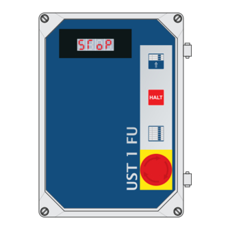
Automatic control unit of industrial door systems with inverter
HALT
IT -
Istruzioni e indicazioni d'installazione e uso
L'intero manuale d'istruzioni è composto delle istruzioni per l'uso rispettivamente del motoriduttore e della relativa centrale di comando.
EN -
Instructions and information for installation and use
The entire instruction manual is made up of instructions for use regarding the gearmotor and its control unit.
FR -
Instructions et indications d'installation et d'utilisation
L'ensemble du manuel d'instructions comprend les instructions pour utiliser respectivement le motoréducteur et sa centrale de commande.
ES -
Instrucciones e indicaciones para la instalación y el uso
El manual de instrucciones está compuesto por las instrucciones de uso del motorreductor y de la central de mando relativa.
DE -
Anweisungen und Hinweise für Installation und Bedienung
Die Gesamt-Bedienungsanleitung besteht aus der BA des Antriebes und der dazugehörigen BA der Steuerung.
PL -
Instrukcja i wskazówki na temat instalacji i eksploatacji
Cała instrukcja obsługi zawiera instrukcje dotyczące obsługi odpowiednio motoreduktora oraz właściwej centrali sterowniczej.
NL -
Instructies en aanwijzingen voor de installatie en het gebruik
De volledige instructiehandleiding bestaat uit de gebruiksaanwijzingen voor het gebruik van respectievelijk de reductiemotor en
van de bijbehorende bedieningscentrale
Inhaltsverzeichnis

Verwandte Anleitungen für Nice UST1-FU


Inhaltszusammenfassung für Nice UST1-FU
- Seite 1 UST1-FU UST1-FU UST1-FU3 Automatic control unit of industrial door systems with inverter HALT IT - Istruzioni e indicazioni d’installazione e uso L‘intero manuale d‘istruzioni è composto delle istruzioni per l‘uso rispettivamente del motoriduttore e della relativa centrale di comando. EN - Instructions and information for installation and use The entire instruction manual is made up of instructions for use regarding the gearmotor and its control unit.
-
Seite 59: Allgemeine Sicherheitshinweise
EINSTELLUNG DER GESCHWINDIGKEIT ANSCHLÜSSE PLATINE UST1-FU Beschreibung und Einsatz SCHALTPLAN UST1-FU TECHNISCHE DATEN - EIGENSCHAFTEN UST1-FU ist ein Torsteuerung für Schnelllauftore mit 3- Phasen TRANSPORT Motoren mit Frequenzumformer. Alle üblichen Sicherungselemente sind anschließbar. SERVICE Zusätzliche Anwendungsmöglichkeiten sind durch das Aufrüsten mit HERSTELLERERKLÄRUNG... -
Seite 60: Bedienelemente Und Anschluss
über den Funk-Handsender immer möglich. Netz - Anschluss 1-Phase - Abb.1 An den Klemmen L1(Phase), L2 (0) und PE ist ein Schukostecker angeschlossen. Der Netzanschluss zur UST1-FU kann auch mit optionalem Hauptschalter erfolgen. Bremskontakt Hierbei wird der Schukostecker bei der Montage entfernt. -
Seite 61: Anschluss Fu - 1-Phasig
Schaltkontakt und die Plusseite der Lichtschrankenelektronik an der Klemme Anschluss einer Sicherheitsleiste mit 8,2 kΩ - Abb.7 J30/1 (X5) mit dem Pluspotential verbunden. An der UST1-FU kann direkt eine elektrische bzw. eine pneumatische Bei Anschluss der Lichtschranke Brücke von J31 Klemmenblock X5 entfernen! Sicherheitsleiste angeschlossen werden. -
Seite 62: Auf, Stop, Ab Und Impuls
Hierzu zählen NOT-AUS bzw. Fangvorrichtung, Einzugsicherung und die Schlupftürabsicherung. Anschluss Funkfernsteuerung (Funkmodul) Auf dem Steckplatz (J38) 10 PINS - kann der Nice Empfänger OXI / OXIFM aus der OPERA Serie aufgesteckt werden. Weiteres siehe Bedienungsanleitung Empfänger und Handsender. Anschluss 3-fach Taster mit 4-adrigem Kabel... - Seite 63 Erforderliche Drahtbrücken und Jumper für die Betriebsbereitschaft der Steuerung bei nicht angeschlossenen Komponenten Drahtbrücken: Jumper: X2-J10 X8-Pin 5-6 X4-J15 X9-Pin 1-2 X5-J31 8,2KΩ-Pin 1-2 X6-J33 Opto-Pin 2-3 Elektronischer Endschalter zusätzlich X7- J26, J27, J28 ACHTUNG: Für die Einstellung ist es empfohlen, das (optionale) K5 Modul auf der Basisplatine zusätzlich zu installieren.
-
Seite 64: Einstellungen Der Automatischen Funktionen
EINSTELLUNGEN DER AUTOMATISCHEN FUNKTIONEN Betriebsfunktionen Reversier Funktion DIP 4 = ON Im normalen Betriebszustand wird in der Wird in der Abfahrt die Sicherheitsleiste betätigt, Anzeige Torzustand bzw. die stoppt das Tor und reversiert ca. 50cm. Fehlernummer des vorliegenden Fehlers DIP 4 = OFF angezeigt. - Seite 65 Elektron. Endschalter Elektron. Endschalter Typ A Typ B Ader 1 ,2 und 3 fünf-polige Anschlußkabel Buchsenleiste Steuerung Anschlußkabel Steuerung sechs-poliger Stecker sechs-poliger Stecker Anschkußkabel Steuerung Steuerungs Anschkußkabel Steuerung Ader Motor X2 - J11/U AMP-Stecker X2 - J11/V Sicherheitskette RS485 A X2 - J11/W Eingang...
-
Seite 66: Einstellungen Der Parameter Am Frequenzumrichter
EINSTELLUNGEN DER PARAMETER AM FREQUENZUMRICHTER Am Frequenzumrichter können verschiedene Parameter eingestellt werden Status/Störungsmeldungen Parameter ändern Code Benennung Einstellbereich Voreingestellt Minimale A usgangsfrequenz 15-‐20 H z 15 H z bei 0 ,75 k W -‐ 1 0 H z Maximale ... -
Seite 67: Drehzahlkurven Mit Zuordnung Der Parametereinstellung
Fehler/ Status Beschreibung Ursache Abhilfe Kurzschlussursache s uchen, leitung p rüfen Kurzschluss Zu h oher k apazitiver L adestrom Kürzere M otorleitung m it der M otorleitung niedrigerem L adestrom v erwenden Kurzschluss ... -
Seite 68: Einstellung Der Geschwindigkeit
EINSTELLUNG DER GESCHWINDIGKEIT Auf der Steuerung UST1-FU befinden sich 3 Potentiometer. Mit dem Poti 1 kann der Schleichgang gemeinsam für beide Bewegungsrichtungen eingestellt werden. Mit dem Poti 2 wird die Geschwindigkeit AUF und mit Poti 3 die Geschwindigkeit AB separat eingestellt. -
Seite 69: Anschlüsse Platine Ust1-Fu
ANSCHLÜSSE PLATINE UST1-FU Steckleiste Steckleiste Schraubklemme Taster Taster Jumper Jumper Funk - nur Funk - OXI/ Antenne Empfänger OXIFIM Anzeige Kontaktleiste DIP-Schalter für Funktions- aktivierung Durchfahrt Lichtschranke Reservejumper Steckleiste Modul K5 3-fach-Taster Befehls- geräte Steckklemme Endschalter Schlüssel- schalter Steckklemme pot.freier Kontakt... -
Seite 70: Schaltplan Ust1-Fu
SCHALTPLAN UST1-FU LEGENDE Schließkantensicherung Steckleiste für Funkempfänger - Nice OXI (Opera System) Jumper 8,2 kW I Opto Jumper 8,2 kW I Opto Steckklemme Netz Steckleiste für Steckmodule (10-polig) Steckklemme Motor Aktivierung mechan. Test DW-Schalter (untere Torposition) Steckklemme potential freier wechslerkontakt potentialfreier Wechsel-Kontakt (Bremse) Steckklemme Befehlsgeräte... -
Seite 71: Technische Daten - Eigenschaften
Der Einbau und / oder die Verwendung solcher Produkte kann daher konstruktiv vorgegebene Eigenschaften der Antriebe negativ verändern und dadurch die Sicherheit beeinträchtigen. Für Schäden, die durch die Verwendung von nicht Original-Ersatzteilen und Zubehör entstehen, ist jede Haftung und Gewährleistung seitens NICE ausgeschlossen. Störungen, die nicht selbst behoben werden können, sollten nur vom Hersteller der Toranlage oder einer anderen Fachfirma beseitigt werden. Dort können ebenfalls Ersatzteile angefordert werden. -
Seite 104: Ce-Konformitätserklärung
Erklärung in Übereinstimmung mit den Richtlinien: 1995/5/EG (R&TTE), 2004/108/EG (EMV); 2006/42/EG (MD) Anlage II, Teil B Anmerkung: Der Inhalt dieser Erklärung entspricht den Angaben im offiziellen Dokument, das im Sitz der Nice S.p.A. hinterlegt ist und der letzten verfügbaren Revision vor dem Druck dieser Anleitung. Dieser Text wurde aus redaktionellen Gründen angepasst. Die Kopie der Original- Erklärung kann bei der Firma Nice S.p.A. - Seite 108 Nice SpA Oderzo TV Italia www.niceforyou.com info@niceforyou.com...