Herunterladen Inhalt Inhalt Diese Seite drucken
Inhaltsverzeichnis

Werbung

Verfügbare Sprachen
  • DE

Verfügbare Sprachen

  • DEUTSCH, seite 53
ATTUATORE ELETTROMECCANICO IRREVERSIBILE 24V PER PORTE SEZIONALI E
I
BASCULANTI A MOLLE E CONTRAPPESI FINO A 65KG
24V IRREVERSIBLE ELECTROMECHANICAL ACTUATOR FOR SECTIONAL SPRING OR
GB
BALANCE WEIGHT GARAGE DOORS UP TO 65KG OF WEIGHT
OPERATEUR ELECTROMECANIQUE IRREVERSIBLE 24V POUR PORTES SÉCTIONNELLES ET
F
BASCULANTES A RESSORTS OU CONTREPOIDS JUSQU' À 65KG
NICHT UMKEHRBARER ELEKTROMECHANISCHER ANTRIEB 24V FÜR SEKTIONALTORE,
D
FEDERSCHWINGTORE UND GEGENGEWICHTTORE MIT MAXIMALEM GEWICHT VON 65KG
OPERADOR ELECTROMECANICO IRREVERSIBLE 24V PARA PUERTAS SECCIONALES Y
E
BASCULANTES CON MUELLES O CONTRAPESOS HASTA 65KG
V2 ELETTRONICA SPA
Corso Principi di Piemonte, 65/67 - 12035 RACCONIGI (CN) ITALY
tel. +39 01 72 81 24 11
fax +39 01 72 84 050
info@v2elettronica.com
www.v2home.com
IL n. 158-A
EDIZ. 04/07/2006

Werbung

Inhaltsverzeichnis
loading

Inhaltszusammenfassung für V2 JET650

  • Seite 1 V2 ELETTRONICA SPA Corso Principi di Piemonte, 65/67 - 12035 RACCONIGI (CN) ITALY tel. +39 01 72 81 24 11 fax +39 01 72 84 050 IL n. 158-A info@v2elettronica.com www.v2home.com EDIZ. 04/07/2006 ATTUATORE ELETTROMECCANICO IRREVERSIBILE 24V PER PORTE SEZIONALI E...
  • Seite 2: Inhaltsverzeichnis

    AVVERTENZE IMPORTANTI ...........1 IMPORTANT REMARKS ............17 CONFORMITÁ ALLE NORMATIVE ...........1 DECLARATION OF CONFORMITY ...........17 DATI TECNICI..............1 TECHNICAL SPECIFICATIONS ..........17 VERIFICHE PRELIMINARI .............2 PRELIMINARY CHECKINGS ..........18 SCHEMA DI INSTALLAZIONE ..........2 INSTALLATION LAYOUT ............18 LIMITI DI IMPIEGO ..............3 USE LIMITS................19 COMPOSIZIONE ..............4 COMPOSITION ..............20 ACCESSORI................5 ACCESSORIES..............21...
  • Seite 3 CONSEILS IMPORTANTS............33 WICHTIGE HINWEISE............49 DECLARATION DE CONFORMITÉ...........33 KONFORMITÄTSERKLÄRUNG..........49 DONNEE TECHNIQUES ............33 TECHNISCHE EIGENSCHAFTEN ..........49 OPERATIONS PREALABLES ..........34 VORKONTROLLEN ...............50 SCHÉMA D’INSTALLATION ...........34 INSTALLATIONSPLAN............50 LIMITE D'EMPLOI..............35 ANWENDUNGSBESCHRÄNKUNGEN ........51 COMPOSITION ..............36 ZUSAMMENSETZUNG ............52 ÉQUIPEMENTS ..............37 ZUBEHORTEILE..............53 MONTAGE ................37 MONTAGE ................53 INSTALLATION ..............39 EINBAU................55 DEBLOCAGE DE L’INTERNE ..........40 FREIGABE VON INNEN............56...
  • Seite 4 ADVERTENCIAS IMPORTANTES ..........65 DECLARACIONES DE CONFORMIDAD........65 DATOS TECNICOS ...............65 VERIFICACIONES PRELIMINARES .........66 SCHEMA DI INSTALLAZIONE ..........66 LIMITACIONES DE USO ............67 COMPOSICION ..............68 ACCESORIOS..............69 MONTAJE ................69 INSTALACION..............71 DESBLOQUO DESDE EL INTERIOR ........72 DESBLOQUO DESDE EL EXTERIOR........73 RESTABLECIMIENTO DE LA AUTOMATIZACION.......73 CONEXION DE LOS BORNES..........74 PRGBCT - CUADRO DE MANIOBRAS PARA PUERTAS BASCULANTES ..........76 APRENDIZAJE AUTOMATICO..........76...
  • Seite 5: Avvertenze Importanti

    AVVERTENZE IMPORTANTI CONFORMITÁ ALLE NORMATIVE Per chiarimenti tecnici o problemi di installazione la V2 ELETTRONICA SPA dichiara che gli attuatori della serie V2 ELETTRONICA dispone di un servizio di assistenza clienti JET-24V sono conformi ai requisiti essenziali fissati dalle attivo durante le ore di ufficio TEL. (+39) 01 72 81 24 11...
  • Seite 6: Verifiche Preliminari

    VERIFICHE PRELIMINARI • La porta deve essere adeguatamente bilanciata sia prima che dopo l'automatizzazione: fermando la porta in qualsiaisi posizione non deve muoversi; eventualmente Prima di procedere con l’installazione di JET-24V è provvedere ad una regolazione dei contrappesi. fondamentale verificare i seguenti punti: •...
  • Seite 7: Limiti Di Impiego

    LIMITI DI IMPIEGO JET-24V è in grado di automatizzare porte sezionali con altezza max. fino a 2,6 m, porte basculanti a molle fino a 2,6 m e porte basculanti a contrappesi fino a 2,8 m. Rispettare le seguenti misure per un buon esito dell’installazione. Per automatizzare porte con altezze superiori è...
  • Seite 8: Composizione

    COMPOSIZIONE 1 motoriduttore elettromeccanico JET-24V con centrale di comando incorporata. * 3 profilati guida in alluminio lunghezza 1m. 1 carrello di traino * 2 trasmettitori HANDY4 4 supporti di fissaggio 1 giunto finale 1 pomello con cordino * 4 barre di giunzione profilato 1 staffa porta 1 barra forata 1 barra curva...
  • Seite 9: Accessori

    ACCESSORI 1 - MONTAGGIO 1.1 Assemblare il profilato guida B utilizzando le apposite barre di giunzione H, i bulloni V1, i dadi D1 e le rondelle R1. Prolunga di montaggio per aumento della corsa di 400 mm completa di elementi di fissaggio 1.2 Nel caso in cui l’installazione richieda il montaggio della prolunga J1, aggiungere il profilato di 400 mm in testa ai profilati precedentemente montati, in modo da poter...
  • Seite 10 C prima di inserire il carrello nel profilato. 2.0 Montare i supporti di fissaggio E: inserire i bulloni V2 e le piastrine forate R negli appositi vani del profilato, adattare i supporti sul profilato in corrispondenza dei bulloni e...
  • Seite 11: Installazione

    2.1 Nel caso in cui sia necessario adattare l'automazione in 2 - INSTALLAZIONE altezza utilizzare le apposite barre forate Q e la staffa P. 2.1 Smontare il sistema di chiusura della porta sostituendolo con lo sblocco a filo. ATTENZIONE: la distanza massima tra profilato e soffitto non deve superare 300 mm.
  • Seite 12: Sblocco Dall'interno

    Unire la squadretta di traino I e la barra forata L tramite l'apposito braccio curvo M utilizzando 2 bulloni V2, 1 bullone V8 e 3 dadi D2. Unire la barra forata L al carrello di traino C utilizzando una vite V5 e un dado D3.
  • Seite 13: Sblocco Dall'esterno

    SBLOCCO DALL'ESTERNO RIPRISTINO DELL'AUTOMAZIONE Per sbloccare l'automazione dall'esterno è necessario installare Per ripristinare l'automazione procedere come segue: l'apposito kit accessorio di sblocco (cod. J5). • Riportare la leva di sblocco C1 nella posizione iniziale. • Azionare il motore con un semplice comando di START: •...
  • Seite 14: Collegamenti Alla Morsettiera

    COLLEGAMENTI ALLA MORSETTIERA LETTORE DI LAMPEGGIANTE LAMPADA SPIA COSTA FOTOCELLULA FOTOCELLULA PROSSIMITÀ (24V - 10W) (24V - 3W) MECCANICA (RX) (TX)
  • Seite 15: Collegamenti Elettrici

    Costa meccanica di sicurezza (CMS) Comando di apertura per il collegamento di VRD (ingresso dati) Comando di apertura per il collegamento di dispositivi tradizionali con contatto N.A. Comando di Stop. Contatto N.C. 5 - 8 - 11 Comune (-) Fotocellula. Contatto N.C. Alimentazione +24VDC 10W per fotocellule (RX) ed altri accessori Lampeggiante +24VDC 10W...
  • Seite 16: Prgbct - Centrale Di Comando

    PRGBCT Vengono automaticamente impostati i seguenti parametri di funzionamento: Centrale di comando per porta basculante La centrale aziona un motore a spazzole a bassa tensione Amperometrica Livello 2 (24 Vdc), per l’automazione di porte sezionali e basculanti. Logica di funzionamento PASSO-PASSO Caratteristiche principali: Rallentamento •...
  • Seite 17: Amperometrica

    AMPEROMETRICA 5. Trasmettere (entro 5s) con il tasto desiderato in base alla TABELLA. Per modificare il livello di amperometrica procedere come segue: 6. La luce si spegne per 2s e quindi visualizza il nuovo 1. Premere e tenere premuto il tasto P1 per 5s (luce accesa) parametro impostato con il relativo numero di lampeggi.
  • Seite 18: Rallentamento, Lampeggiante Elampada Spia

    RALLENTAMENTO, LAMPEGGIANTE E PRELAMPEGGIO E TEST FOTOCELLULE LAMPADA SPIA Per impostare il prelampeggio e il test delle fotocellule procedere come segue: Per impostare il rallentamento, il lampeggiante e la lampada spia procedere come segue: 1. Premere e tenere premuto il tasto P1 per 5s (luce accesa) e contemporaneamente trasmettere con il tasto 4 del 1.
  • Seite 19: Spinta Finale In Chiusura

    SPINTA FINALE IN CHIUSURA APPRENDIMENTO VIA RADIO DI NUOVI Per impostare la spinta finale in chiusura procedere come TRASMETTITORI segue: • Premere contemporaneamente i tasti 1 +2 o 1+3, di un trasmettitore già memorizzato, per 10 secondi, rilasciare i 1. Premere e tenere premuto il tasto P1 per 5s (luce accesa) tasti quando la luce di cortesia emette 1 lampeggio.
  • Seite 20: Risoluzione Dei Problemi

    TRAMITE PULSANTE P1. la porta correttamente La scheda radio potrebbe essere danneggiata: consultare l' Ufficio Assistenza Tecnica V2 Verificare il corretto collegamento del pulsante di Start esterno: se il pulsante Il collegamento sulla morsettiera del P1 attiva l'automazione il problema è...
  • Seite 21: Important Remarks

    TEL. (+39) 01 72 81 24 11 actuators are in conformity with the provisions of the following EC directives: V2 ELETTRONICA has the right to modify the product without previous notice; it also declines any responsibility to damage 73/23/EEC electrical safety...
  • Seite 22: Preliminary Checkings

    PRELIMINARY CHECKINGS • The door must be properly balanced both before and after its automation: stopping the door in any position, it must not move (carry out a balance weight adjustment, if necessary). Before installing JET-24V, please check the following basic points: •...
  • Seite 23: Use Limits

    USE LIMITS JET-24V can automate sectional doors max 2,6 m high, balanced doors max 2,6 m and counterweight balanced door max 2,8 m. Take into consideration in order to install properly. In order to automate higher doors it is necessary to install the mounting extension J1. Take into consideration in order to install properly.
  • Seite 24: Composition

    COMPOSITION 1 electromechanical geared motor JET-24V with built-in control unit. * 3 aluminium section bar guides 1m long. 1 draft truck * 2 HANDY4 tansmitters 4 fastening supports 1 final joint 1 doorknob with string * 4 section guide bars 1 door bracket 1 drilled bar 1 curved bar...
  • Seite 25: Accessories

    ACCESSORIES 1 - ASSEMBLY 1.1 Assemble the section bar guide B by means of the junction bars H, bolts V1, nuts D1 and washers R1. - Mounting extension for 40 cm run increase. Provided with fixing elements for sectional doors and counterweight balanced doors up to 3 m of height.
  • Seite 26 C hole before putting the truck into the section bar. 2.0 Assemble fastening supports E: insert bolts V2 and drill plates R into the special section bar spaces, then adapt such supports on the section bar with reference to the...
  • Seite 27: Installation

    2.1 In case you need to lower the automation in height, make 2 - INSTALLATION use of the special drilled bars Q and bracket P. 2.1 Disassemble the door locking system and replace it with the wire unlocking. WARNING: the maximum distance between the section 2.2 Measure the exact door half and trace some reference bar guide and the ceiling should not excede 300 mm.
  • Seite 28: Release From Inside

    2.4 Following the reference points, which have been previously 2.6 For counterweight balanced doors only traced on the ceiling, identify the fastening points for Fasten the sliding arm J4 on the door upper part by supports E or bracket P, then drill and using plugs following the previous reference points.
  • Seite 29: Release From Outside

    RELEASE FROM OUTSIDE AUTOMATION RESTARTING Install the special accessory release kit to release the To restart the automation use proceed as follows: automation from outside (cod. J5). • Bring the C1 unblocking lever back to the initial position. • Activate the motor with a START input: the slider will hook •...
  • Seite 30: Terminal Connections

    TERMINAL CONNECTIONS PROXIMITY BLINKER WARNING LIGHT SAFETY RIB PHOTOCELL PHOTOCELL READER (24V - 10W) (24V - 3W) (RX) (TX)
  • Seite 31: Electric Connections

    Mechanical safety rib (CMS) Opening command to connect VRD (data input) Opening command to connect traditional devices having normally open contact Stop command. Normally closed contact 5 - 8 - 11 Common (-) Photocell. Normally closed contact +24VDC 10W photocell (RX) power supply and other accessories +24VDC 10W blinker Compulsory TX photocells power supply +24VDC...
  • Seite 32: Prgbct - Control Unit For Garage Door

    PRGBCT The following functioning parameter will be automatically setted: Control unit for garage door Current sensor level: Level 2 The control unit activates a low voltage (24Vdc) brush motor for the automation of both side and sliding doors. Functioning logic: Step by step Slowing down: Main characteristics:...
  • Seite 33: Current Sensor Level

    CURRENT SENSOR LEVEL 5. Transmit (within 5sec) with the ideal key according to the CHART. To modify the current sensor level procede as follow: 6. The courtesy light switch off for 2 sec and therefore it 1. Press and keep pressed the key P1 for 5sec (courtesy light visualizes the new level setted with the relative number of ON) and at the same time transmit with the key 1 of the flashes.
  • Seite 34: Slowing Down, Blinker And Warning Light

    SLOWING DOWN, BLINKER AND PRE-FLASHING AND PHOTOCELL TEST WARNING LIGHT To set the pre-flashing and the photocell test procede as follow: To set the slowing down, the blinker and the warning light 1. Press and keep pressed the key P1 for 5sec (courtesy light procede as follow: ON) and at the same time transmit with the key 4 of the transmitter (the transmission must last 3 sec).
  • Seite 35: Final Closing Thrust Force

    FINAL CLOSING THRUST FORCE NEW TRANSMITTER RADIO LEARNING To set the final closing thrust force proceed as follows: • Press at the same time the push-buttons 1 +2 or 1+3 of a transmitter which has been already stored and keep them 1.
  • Seite 36: Problem Solving

    TRANSMITTER BYMEANSE OF P1 KEY. The start RADIO input doesn't move the The transmitter is not properly set door The radio card could be damaged: call V2 Technical Assistance Dept. Check the proper connection to the The connection to the terminal board is...
  • Seite 37: Conseils Importants

    CONSEILS IMPORTANTS DECLARATION DE CONFORMITÉ Pour tout précision technique ou problème d’installation V2 ELETTRONICA SPA déclare que les opérateurs de la série V2 ELETTRONICA dispose d’un service d’assistance clients actif JET-24V sont conformes aux qualités requises par les Directives: pendant les horaires de bureau TEL. (+39) 01 72 81 24 11 73/23/EEC sécurité...
  • Seite 38: Operations Prealables

    OPERATIONS PREALABLES • La porte doit être bien balancée soit avant que après l'automatisation: en arrêtant la porte en n'importe quelle position, ne doit pas bouger ; éventuellement il faut établir Avant de procéder avec l'installation de JET-24V il est impératif une régulation des contrepoids.
  • Seite 39: Limite D'emploi

    LIMITE D'EMPLOI JET-24V est en condition d'automatiser portes sectionnelles avec hauteur jusqu'à maximum 2,6 m, portes basculantes à ressort jusqu'à 2,6 m. et portes basculantes à contrepoids jusqu'à 2,8 m. Pour un bon succès de l'installation, respecter ces quotas. Pour automatiser portes avec hauteur supérieur il faut installer le prolongement J1. Pour un bon succès de l'installation, respecter ces quotas.
  • Seite 40: Composition

    COMPOSITION 1 moto réducteur électromécanique JET-24V avec armoire de commande intégré * 3 profilés guide en aluminium longueur 1m. 1 chariot de tirage * 2 émetteurs HANDY4 4 supports fixation 1 joint final 1 poignée avec cordonnet * 4 barres de jonction profilé 1 étrier porte 1 barre percée 1 barre curbée...
  • Seite 41: Équipements

    ÉQUIPEMENTS 1 - MONTAGE 1.1 Raccorder le profilé B en utilisant les barres de jonction H, les boulons V1, les écrous D1 et les rondelles R1. J1 - Prolongement de montage pour augmenter la course de 40 cm. Complète des éléments de fixation, pour portes sectionnelles et basculantes jusqu'à...
  • Seite 42 C avant d’insérer le chariot dans le rail. 2.0 Monter les support de fixation E: insérer les boulons V2 et les tôle de serrage R dans le rail, adapter les support sur le rail en correspondance des boulons et fermer les...
  • Seite 43: Installation

    2.1 En cas il soit nécessaire adapter l’automatisme en 2 - INSTALLATION hauteur, utiliser les tôles de fixation Q et l’éclisse P. 2.1 Démonter le système de fermeture de la porte en le remplaçant avec le déblocage à fil. ATTENTION: la distance maximum entre le rail et le plafond ne doit pas depasser 300 mm.
  • Seite 44: Deblocage De L'interne

    2.4 En suivant les points tracés à l’avance sur le plafond, 2.6 Pour portes basculantes à contrepoids localiser les points de fixation pour les supports E ou Fixer le bras courbé J4 sur la partie supérieure de la porte l’étrier P, percer et, en utilisant des goujons appropriés au en suivant les points tracés à...
  • Seite 45: Deblocage De L'externe

    DEBLOCAGE DE L’EXTERNE RETABLISSEMENT DE L'AUTOMATISME Pour débloquer l’automatisme de l’externe il faut installer le kit Pour rétablir l'automatisme proceder de façon suivante: de déblocage (cod. J5) • Reporter le levier de deblocage C1 dans la position initale. • Insérer le fil métallique dans le trous du chariot de guidage. •...
  • Seite 46: Branchements A La Borniere

    BRANCHEMENTS A LA BORNIERE LECTEUR DE CLIGNOTANT LAMPE REGARD BARRE PHOTOCELLULE PHOTOCELLULE PROXIMITÉ (24V - 10W) (24V - 3W) PALPEUSE (RX) (TX)
  • Seite 47: Branchements Electriques

    Barre palpeuse (CMS) Commande de ouverture pour le branchement du VRD (entrée données) Commande de ouverture pour le branchement des dispositifs traditionnels avec contact normalement ouvert. Commande Stop. Contact normalement fermé 5 - 8 - 11 Commun (-) Photocellule. Contact normalement fermé Alimentation obligatoire pour photocellule (TX) +24VDC 1W pour test fonctionnel Clignotant +24VDC 10W...
  • Seite 48: Prgbct - Armoire De Commande Pour

    PRGBCT Sont automatiquement établis les paramètres suivantes de fonctionnement: Armoire de commande pour porte basculante La centrale actionne un moteur à brosse en basse tension Ampèremétrique Niveau 2 (24 VDC), pour l’automatisation de portes sectionnelles et basculantes. Logique de fonctionnement PAS-PAS Ralentissement Caractéristiques principales:...
  • Seite 49: Amperemetrique

    AMPEREMETRIQUE 5. Transmettre (sous 5 s) avec la touche souhaitée selon le TABLEAU. Pour modifier le niveau de ampèremétrique procéder comme il suive: 6. La lumière s’éteigne pour 2 s et après visualise le nouveau paramètre établit avec le relatif nombre de clignotements. 1.
  • Seite 50: Ralentissement, Clignotant Et Warning Light

    RALENTISSEMENT, CLIGNOTANT ET PRECLIGNOTEMENT ET TEST PHOTOCELLULE WARNING LIGHT Pour programmer le préclignotement et le test des photocellules procéder comme il suive: Pour programmer le ralentissement, le clignotant et le warning light procéder comme il suive: 1. Appuyer et maintenir la touche P1 pour 5s (lumière allumée) et en même temps transmettre avec la touche 4 de 1.
  • Seite 51: Poussee Finale En Fermeture

    POUSSEE FINALE EN FERMETURE APPRENTISSAGE VIA RADIO DES NUOVEAUX Pour régler la poussée finale en fermeture, procéder comme EMETTEURS suive : • Appuyer en même temps les touches 1 +2 ou 1+3, d’un émetteur dèjà memorisé, pour 10 seconds, relâcher les 1.
  • Seite 52: Resolution Des Problemes

    La platine radio pourrait être dommagée : consulter le Service Assistance Technique chez V2 Vérifier que le branchement de la touche de Start extérieure soit correcte : si la Le branchement à la bornière de la touche touche P1 active l'automation, le problème...
  • Seite 53: Wichtige Hinweise

    WICHTIGE HINWEISE KONFORMITÄTSERKLÄRUNG Für tecnische Erläuterungen oder Installtionsprobleme verfügt V2 ELETTRONICA SPA erklärt daß die Antriebe der Serie JET-24V die Firma V2 ELETTRONICA über einen Kundendienst, der zu den folgenden Richtlinien entsprechen: Bürozeiten unter der Telefonnummer (+39) 01 72 81 24 11 erreicht werden kann.
  • Seite 54: Vorkontrollen

    VORKONTROLLEN • Das Tor muss sich frei und ohne irgendwelche Reibungspunkte öffnen und schließen lassen. Vor dem Beginn der Installation des JET-24V sind grundsätzlich • Das Tor muss sowohl vor als auch nach der Automatisierung folgende Punkte zu kontrollieren: entsprechend ausbalanciert werden: Bei Anhalten des Tors in welcher Position auch immer, darf sich dieses nicht bewegen;...
  • Seite 55: Anwendungsbeschränkungen

    ANWENDUNGSBESCHRÄNKUNGEN JET-24V ist in der Lage, Sektionaltore bis max. 2,6 m, Federschwingtore bis max. 2,6 m und Gegengewicht-Schwingtore bis max. 2,8 m Höhe zu automatisieren. Zur korrekten Montage nachfolgende Abmessungen beachten. Zum Automatisieren von Toren mit einer größeren Höhe ist die Verlängerung J1 zu installieren. Zur korrekten Montage nachfolgende Abmessungen beachten.
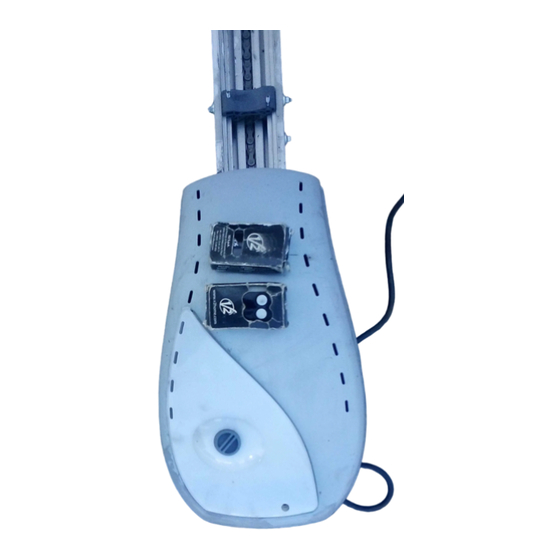
  • Seite 56: Zusammensetzung

    ZUSAMMENSETZUNG 1 elektromechanischer Getriebemotor JET-24V mit eingebauter Steuerzentrale. * 3 Aluminiumprofilteile als Führung der Länge 1 m. 1 Zugschlitten * 2 Sender HANDY4 4 Befestigungshalterungen 1 Endverbindungsstück 1 Knauf mit Schnur * 4 Profilverbindungsriegel 1 Torbügel 1 gelochter Riegel 1 gebogener Riegel 1 Bügel 1 Plakette 3 Bügel...
  • Seite 57: Zubehorteile

    ZUBEHORTEILE 1 - MONTAGE 1.1 Das Führungsprofilteil B zusammenbauen, indem man die entsprechenden Verbindungsriegel H, die Schrauben V1, die Muttern D1 und die Unterlegscheiben R1 verwendet. - Montageverlängerung zum verlängern des Wegs um 40cm, komplett mit den Notwendigen Befestigungselementen für Tore bis 3m Höhe. 1.2 Sollte die Installation die Montage der Verlängerung J1 erfordern, das 400mm-Profilteil so an das Kopfstück der vorher montierten Profilteile montieren, dass man Teil F an...
  • Seite 58 Schlittens in das Profilteil, das Metallseil in das entsprechende Loch am Zugschlitten C einzuführen. 2.0 Die Befestigungshalterungen E montieren: Die Schraubbolzen V2 und die gelochten Plättchen R in die vorgesehenen Stellen des Profilteils einsetzen, die Halterungen am Profilteil an den Schraubbolzen anpassen...
  • Seite 59: Einbau

    2.1 Sollte der Mechanismus in seiner Höhe anzupassen sein, 2 - EINBAU bitte die entsprechenden Lochleisten Q und den Bügel P verwenden. 2.1 Das Torschließsystem ausbauen und es mit dem Seilfreigabemechanis-mus austauschen. ACHTUNG: Der maximale Abstand zwischen Profil 2.2 Die exakte Hälfte des Tores messen und und Decke darf 300 mm nicht überschreiten.
  • Seite 60: Nur Für Unterteilte Tore Und Federschwingtore

    2.4 Mit Hilfe der vorher angebrachten Markierungspunkte die 2.6 Nur für Schwingtore mit Gegengewichten Befestigungspunkte für die Halterungen E oder den Bügel Den gebogenen Arm J4 am oberen Teil des Tores unter P fixieren, lochen und unter Verwendung von für den Berücksichtigung der vorher angebrachten Markierungen Deckentyp geeigneten Dübeln (ø...
  • Seite 61: Freigabe Von Aussen

    FREIGABE VON AUSSEN WIEDERINBETRIEBSETZUNG DER AUTOMATION Zur Freigabe des Automatik von außen ist es notwendig, das Um die Automation in Betrieb wieder zu setzen, machen Sie wie entsprechende Zubehörkit zur Freigabe einzubauen (Cod. J5). folgt: • Das Metallseil in das entsprechende Loch des •...
  • Seite 62: Anschlüsse Am Klemmenbrett

    ANSCHLÜSSE AM KLEMMENBRETT KONTAKTLOSES BLINKLEUCHTE SIGNALLEUCHTE SICHERHEITS FOTOZELLEN FOTOZELLEN LESESYSTEM (24V - 10W) (24V - 3W) VORRICHTUNG (RX) (TX)
  • Seite 63: Elektrische Anschlüsse

    Sicherheitsvorrichtung (CMS) Ausschaltbefehl für den VRD-Anschluss (Dateneingang) Ausschaltbefehl für den Anschluss traditioneller Vorrichtungen mit NO-Kontakt Stopp-Befehl. NC-Kontakt 5 - 8 - 11 Allgemein (-) Fotozelle. NC-Kontakt Versorgung +24VDC 10W für Fotozelle (RX) und sonstiges Zubehör Blinkleuchte +24VDC 10W Obligatorische Versorgung der Fotozelle (TX) +24VDC 1W für Funktionstest Signalleuchte +24VDC 3W 13 - 14...
  • Seite 64: Steuerung Prgbct Für Schwingtore

    Steuerung PRGBCT für Schwingtore Die folgenden Betriebsparameter werden automatisch einggestellt: Die Steuerung betreibt einen Bürstenmotor mittels Niederspannung (24 Vdc) für die Automation von Sektions- und Schwingtoren. Amperemeter: Level 2 Haupteigenschaften: Betriebslogik: SCHRITTWEISE • Speiser "Switching" 140W. • Ausgänge: 24Vdc für Zubehörteile, Blinkleuchte 24Vdc (2Hz) Verlangsamung: Signalleuchte 24Vdc, Versorgung TX-Fotozelle, Innenleuchte Blinkleuchte:...
  • Seite 65: Amperemeter

    AMPEREMETER 4. Das Licht schaltet sich 2 Sekunden lang ab und schaltet sich in Erwartung eines Sendevorgangs 5 Sekunden lang wieder. Zum Ändern des Amperemeterbereichs wie folgt vorgehen: 5. (Innerhalb von 5 Sekunden) mit der gewünschten Taste 1. Taste P1 drücken und 5 Sekunden gedrückt halten (Licht entsprechend der TABELLE senden.
  • Seite 66: Verlangsamung, Blinkleuchte Und Signallampe

    VERLANGSAMUNG, BLINKLEUCHTE UND VORBLINKEN UND FOTOZELLENTEST SIGNALLAMPE Zum Einstellen des Vorblinkens und des Fotozellentests wie folgt vorgehen: Zum Einstellen der Verlangsamung, der Blinkleuchte und Signallampe wie folgt vorgehen: 1. Taste P1 drücken und 5 Sekunden gedrückt halten (Licht eingeschaltet) und gleichzeitig mit Taste 4 des Senders 1.
  • Seite 67: Endschub Beim Schliessen

    ENDSCHUB BEIM SCHLIESSEN FUNKEMPFANG NEUER SENDER Zum Einstellen des Endschubs beim Schließen wie folgt • Drücken Sie gleichzeitig die Tasten 1+2 oder 1+3 eines vorgehen: bereits gespeicherten Senders für 10 Sekunden und lassen Sie die Taste los, sobald die Innenleuchte 1-mal aufblinkt. 1.
  • Seite 68: Lösung Der Probleme

    Die Start-Funkfernsteuerung betätigt das MITTELS TASTE P1 wiederholen. Der Sender ist nicht korrekt gespeichert. Tor nicht. Die Funkkarte könnte beschädigt sein: Das Technische Kundendienstbüro V2 konsultieren. Den korrekten Anschluss der äußeren Starttaste kontrollieren: wenn die Taste P1 Der Anschluss am Klemmenbrett der die Automatisierung aktiviert, liegt das äußeren Starttaste ist nicht korrekt.
  • Seite 69: Advertencias Importantes

    ADVERTENCIAS IMPORTANTES DECLARACIONES DE CONFORMIDAD Para aclaraciones técnicas o problemas de instalación V2 ELETTRONICA SPA declara que los actuadores de la serie V2 Elettronica dispone de un servicio de asistencia a clientes JET-24V son conformes con los requisitos esenciales fijados por activo durante el horario de oficina TEL.
  • Seite 70: Verificaciones Preliminares

    VERIFICACIONES PRELIMINARES • La puerta tiene que ser adecuadamente equilibrada, tanto antes como después de la automatización: parando la puerta en cualquier posición no tiene que moverse; eventualmente Antes de proceder con la instalación de JET-24V es fundamental proceder con una regulación de los contrapesos. verificar los siguientes puntos: •...
  • Seite 71: Limitaciones De Uso

    LIMITACIONES DE USO JET-24V puede automatizar puertas seccionales con altura máx. hasta 2,6 m, puertas basculantes de muelles hasta 2,6 m y puertas basculantes con contrapesos hasta 2,8 m. Respectar las siguientes medidas para un correcto funcionamiento de la instalación. Para automatizar puertas de alturas superiores es necesario instalar la prolongación J1.
  • Seite 72: Composicion

    COMPOSICION 1 motorreductor electromecánico JET-24V con cuadro de maniobras incorporado. * 3 perfiles guía en aluminio de longitud 1m. 1 carro de arrastre * 2 emisores HANDY4 4 soportes de fijación 1 grupo anterior de fijación 1 pomo con cuerda * 4 barras de unión del perfil 1 chapa angular de arrastre 1 barra agujereada...
  • Seite 73: Accesorios

    ACCESORIOS 1 - MONTAJE 1.1 Ensamblar el perfil guía B utilizando las barras de unión H, los tornillos V1, las tuercas D1 y las arandelas R1. - Prolongación de la guía de 40 cm, completa de elementos de fijación, permitiendo la apertura de puertas seccionales y basculantes hasta 3 m de altura.
  • Seite 74 C antes de introducir el carro en el perfil. 2.0 Montar los soportes de fijación E: introducir los tornillos V2 y las chapitas agujereadas R en los alojamientos correspondientes del perfil, adaptar los soportes en el perfil en correspondencia de los tornillos y cerrar las...
  • Seite 75: Instalacion

    2.1 En el caso de que sea necesario adaptar el automatismo 2 - INSTALACION en altura, utilizar las barras agujereadas precisas Q y el soporte P. 2.1 Desmontar el sistema de cierre de la puerta sustituyéndolo con el kit de desbloqueo con cuerda metálica. ATENCION: la distancia maxima entre el perfil guía y el 2.2 Medir la mitad exacta de la puerta y marcar unos puntos techo no debe pasar 300 mm.
  • Seite 76: Desbloquo Desde El Interior

    2.4 Siguiendo las referencias anteriormente marcadas en el 2.6 Solo para puertas basculantes con contrapesos techo localizar los puntos de fijación para los soportes de Fijar el brazo arqueado J4 en la parte superior de la fijación E o el soporte P, agujerear y utilizando unos tacos puerta siguiendo las referencias anteriormente marcadas.
  • Seite 77: Desbloquo Desde El Exterior

    DESBLOQUO DESDE EL EXTERIOR RESTABLECIMIENTO DE LA AUTOMATIZACION Para desbloquear el automatismo desde el exterior es Para restablecer la automatización proceder de la siguiente forma: necesario instalar el accesorio kit de desbloqueo (cod. J5). • Volver a colocar la palanca de desbloqueo C1 en la posición inicial.
  • Seite 78: Conexion De Los Bornes

    CONEXION DE LOS BORNES LECTOR DE LÁMPARA DE LÁMPARA PILOTO BANDA FOTOCÉLULA FOTOCÉLULA PROXIMIDAD SEÑALIZACIÓN (24V - 3W) MECÁNICA (RX) (TX) (24V - 10W)
  • Seite 79: Conexiones Electricas

    Banda mecánica de seguridad (CMS) Comando de apertura para la conexión de VRD (entrada datos) Comando de apertura para la conexión de dispositivos tradicionales con contacto N.A. Comando de Stop. Contacto normalmente cerrado 5 - 8 - 11 Común (-) Fotocélula.
  • Seite 80: Para Puertas Basculantes

    PRGBCT Se programan automáticamente los siguientes parámetros de funcionamiento: Cuadro de maniobras para puertas basculantes El cuadro acciona un motor con escobillas en baja tensión Amperométrica Nivel 2 (24 Vdc), para la automatización de puertas seccionales y basculantes. Lógica de funcionamiento PASO-PASO Paro suave Características principales:...
  • Seite 81: Amperometrica

    AMPEROMETRICA 4. La luz se apaga durante 2 seg. y después se vuelve a encender durante 5 seg. en espera de una transmisión del mando. Para modificar el nivel de amperométrica proceder de la siguiente forma: 5. Transmitir (antes de 5 seg.) con la tecla que se desea en función de la TABLA.
  • Seite 82: Paro Suave, Lampara De Señalizacion Y

    PARO SUAVE, LAMPARA DE SEÑALIZACION Y PREDESTELLO Y TEST FOTOCELULAS LAMPARA PILOTO Para programar el predestello y el test de las fotocélulas proceder de la siguiente forma: Para programar el paro suave, la lámpara de señalización y lámpara piloto proceder de la siguiente forma: 1.
  • Seite 83: Empuje Final En Cierre

    EMPUJE FINAL EN CIERRE APRENDIZAJE VIA RADIO DE LOS NUEVOS Para programar el empuje final en cierre proceder de la EMISORES siguiente forma: • Pulsar contemporáneamente las teclas 1+2 o 1+3, de un emisor ya memorizado, durante 10 segundos, soltar las 1.
  • Seite 84: Solucion De Problemas

    La tarjeta radio podría estar dañada: consultar el Servicio de Asistencia Técnica V2 Verificar la correcta conexión del pulsador La conexión en los bornes del pulsador de de Start exterior: si la tecla P1 activa el start exterior no es correcto...
  • Seite 88 V2 ELETTRONICA SPA Corso Principi di Piemonte, 65/67 - 12035 RACCONIGI (CN) ITALY tel. +39 01 72 81 24 11 fax +39 01 72 84 050 info@v2elettronica.com www.v2home.com...

Diese Anleitung auch für:

Jet650-120vJet-24v

Inhaltsverzeichnis